Announcement

Collapse
No announcement yet.

The reason for 1/4 wave length

Collapse
X
 
  • Filter
  • Time
  • Show
Clear All
new posts

  • The reason for 1/4 wave length

    Greetings every one, this will be my first real post I hope you all find it interesting and enlightening, I am a private researcher and currently a college student, I've been replicating Tesla, Bendini, and Stiffler projects for quite a while and I've decided to share some of the knowledge that I've learned, hope it helps.

    Firstly in order to understand this concept you kneed to know how a spinning toroid or smoke ring is created. So first of if you have ever smoked and you know how to make smoke rings you would first breath out a cloud so that its traveling at a reasonable velocity, they you would sharply inhale, this causes the cloud to be formed into a spinning ring, that will carry the smoke for quite a distance before it breaks up.

    Now to apply this to electronics, suppose we have very large secondary with many turns of fine wire, and a secondary out of 2 or 3 turns of large gauge wire. We start off by tuning the signal in the secondary to 1/4 wave length. Now as we watch the coil we see a electromagnetic field build up around the coil and then the primary suddenly shuts off but the field on the secondary is still there (this is because the secondary has many more turns and its inductance is much higher therefore the change in the em field will be much slower) as the primary shuts off there is a back emf because there is no longer voltage being applied to the coil, this is the smokers sharp inhale that creates the spinning ring, and likewise a spinning ring of em energy is created that can travel a great distance without being broken up(this works best when the primary is driven at 1/4 wave length of the secondary). If this em ring strikes a mass the energy will be released in the substance it strikes, if it is conducting a large current will occur.
    Now the shape of your coil is very important for creating the spinning ring. For a coil wound on a pipe where the sides a perpendicular the spinning ring is created on the normal of the coil sides, basically the spinning ring only increases in diameter and does not travel in the upward or down ward directions. However suppose we had a coil that wound on a cone with the edges 45 degrees apart the ring will travel upwards with increasing diameter at the same rate. now suppose that we had a pancake coil wound on a flat surface, this would create a ring that travels upward at a very high velocity without increasing in diameter, this wave will be able to travel very far before its energy is released to the surroundings, its the basis for Tesla's Death ray and wireless transmission of energy.

    Any way I hope this helped some of you, I would have posted pictures of these devices in action but at the moment I don't have a camera please comment I would like to know what you think

  • #2
    I agree. I wasn't able to see it as whirls but it is very possible that such form it take. Long time ago I understood that to release energy in the non reflecting manner is by such breaking , like happen in the car accident - by abruptly stop at the peak of accumulation ( imagine a car stopped by a brick wall - energy is released destructively , much less is reflected - cars are damaged in place instead of being pushed out).

    Comment


    • #3
      Yes it is pretty hard to visualize with out pictures, one way to make more sense out if it would be to take a slinky and tape or glue the ends together. If you put a pipe in the center slinky and watch the slinkys rotation as you move it along the pipe this will tell you how the wave travels through space or along a waveguide(aka the pipe) hope this helps

      Comment


      • #4
        I follow the smoke ring analogy. I am a Chiropractor and I do a low force adjustment and I visualize it as a smoke ring force. What seems to be important in my work anyway is the void inside the ring and not the spinning smokey part.
        The void allows for the structures to move toward my hands.
        To take the analogy further to electrification, the void created by the smoke ring electrical field allows the universal energy to fill in for the void. The greater the void, the greater the flow of universal energy toward it.

        If a clean enough void can be generated, massive amounts of energy will follow. Its a law of the universe.

        Comment


        • #5
          Originally posted by wyndbag View Post
          I follow the smoke ring analogy. I am a Chiropractor and I do a low force adjustment and I visualize it as a smoke ring force. What seems to be important in my work anyway is the void inside the ring and not the spinning smokey part.
          The void allows for the structures to move toward my hands.
          To take the analogy further to electrification, the void created by the smoke ring electrical field allows the universal energy to fill in for the void. The greater the void, the greater the flow of universal energy toward it.

          If a clean enough void can be generated, massive amounts of energy will follow. Its a law of the universe.
          wyndbag, your experience with the smoke ring projection is quite interesting .... as i do not desire to derail the topic of this thread...could you give some details on the process of the creation of the smoke ring.....If it is ok with you, i 'll be looking forward to reading your answer in the following thread: http://www.energeticforum.com/psychi...tml#post185367 ... so as to keep the topic of this thread on track


          ps: just for info 1/4 wave is HM 7 (see pyramid measurements ) and Tesla obsessed with the Number 3
          Last edited by MonsieurM; 03-22-2012, 01:26 PM.
          Signs and symbols rule the world, not words nor laws.” -Confucius.

          Comment


          • #6
            ah very interesting wyndbag, its neat to see parallels between electrical and physical applications.

            Comment


            • #7
              I am enjoying exploring this too. Since I am too old to learn the math, I relate to the less abstract pictographic approach.
              The quarter wave in the body is represented by the knee. To energize the body, stretch the calves. The calves are often referred to as the 2nd heart.

              Comment


              • #8
                Originally posted by Leviathan View Post
                Now to apply this to electronics, suppose we have very large secondary with many turns of fine wire, and a secondary out of 2 or 3 turns of large gauge wire.
                I am confused by this statement. A very large secondary of what? A standard transformer, or a Tesla Magnifying Transmitter, or a toroid? And also what is the importance of comparing two different types of secondary, one with thicker gauge and less turns the other thinner and more turns?

                Also how exactly does tuning to 1/4 wavelength produce the em ring? Tesla was using 1/4 wavelength because it was the smallest length of wire that could sustain a natural standing wave, with the greatest amplitude (pressure) fluctuation. This was in his TMT.


                Source: ~60% way down through Chapter 3 of free energy info

                Tesla often made extensive use of Impulses, the Impulse can be imagined to create a quick "pressure" differential, which appears to be the same principle that Vortex ring guns use.


                I would think that producing a em ring that decreases in size over time (contracting) might have the most interesting power concentrating/focusing like effect. Brilliant creative ideas Leviathan! I will be definitely looking into ways of producing em rings, and also on a related note I want to produce an em vortex as well.
                A collection of Eric Dollards latest posts and writings on my website: Gestalt Reality - Eric Dollard

                Comment


                • #9
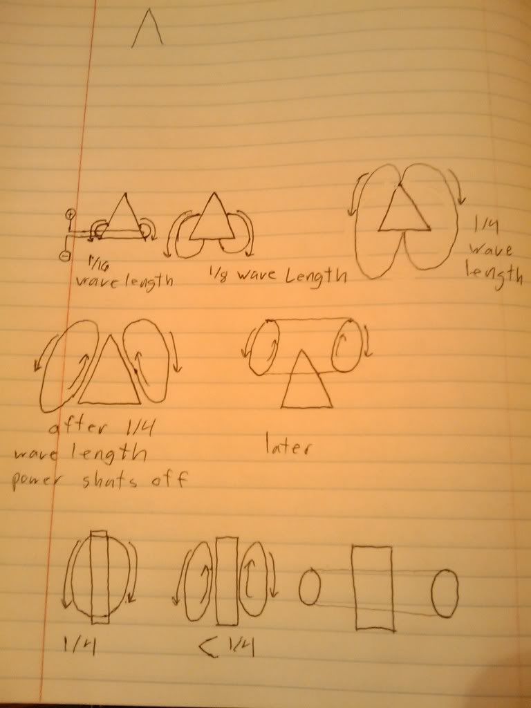
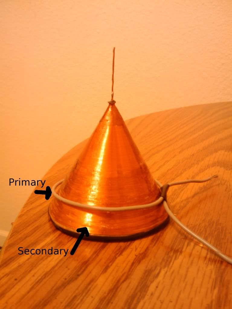
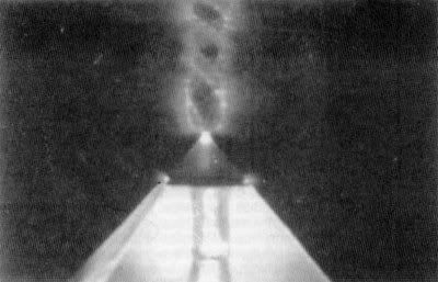
                  Ok finally got a camera and took some pictures, makes a lot more sense once you can see it


                  Comment


                  • #10
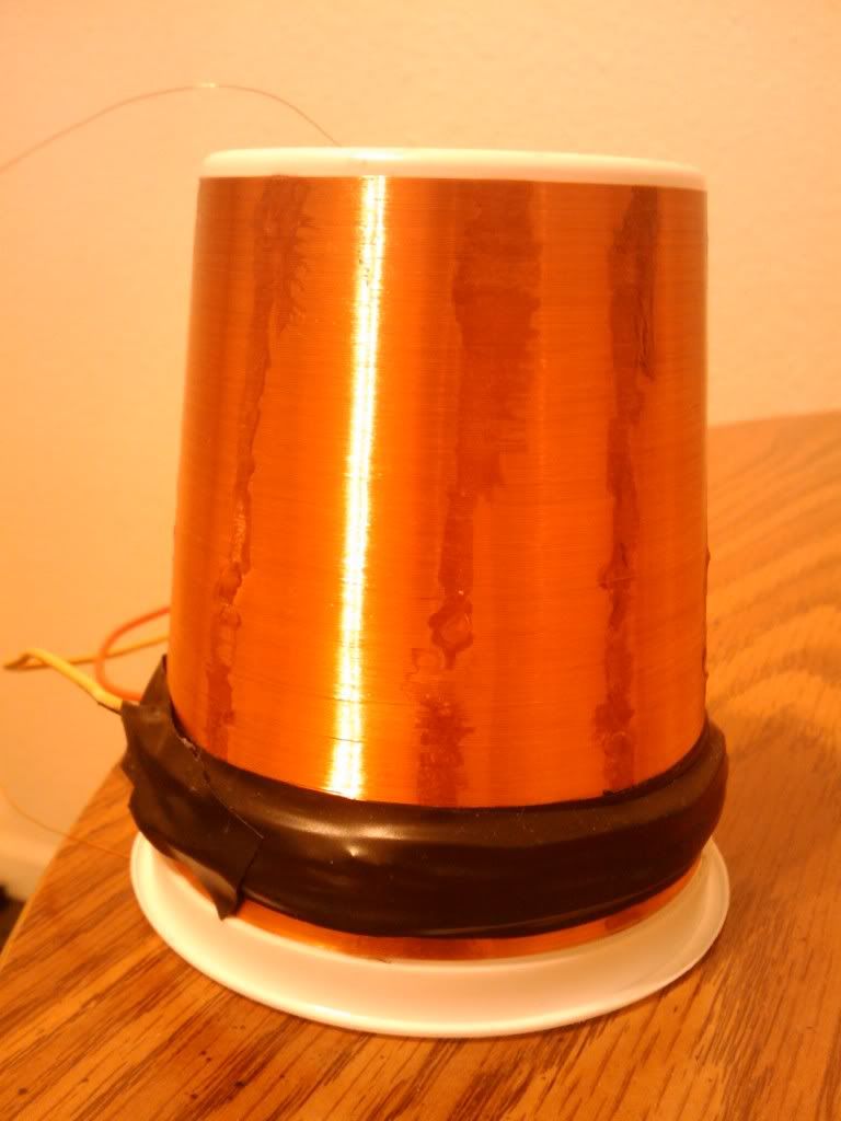
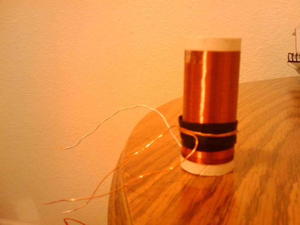
                    these are some of the coils I've been using, I run them at around 250-350 KHz
                    using a slayer circuit with a TIP2N3055. With the big fat coil I can transmit enough energy up to 2 feet away to light a low powered led, the circuit driving it was pulling .04 amps at 4.16 volts, thats about .16 watts. The receiver I use is just separated conducting masses that I connect to the led, it doesn't use a induction coil as a receiver it would be quite impossible to transmit that much energy with induction using the power levels that its running at. Also the denser the mass the more energy is received, this next week I will be casting some lead to make some very sensitive receivers I hope to have some more pictures of my device in operation soon and more details on the receivers.

                    Comment


                    • #11
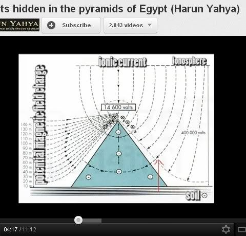
                      Leviathan, your drawings correspond quite amazingly to the pyramid set up and HM 7 / 1/4 wave :


                      Originally posted by Leviathan View Post
                      Ok finally got a camera and took some pictures, makes a lot more sense once you can see it


                      Very interesting Set up .... Thank you for sharing your experiences
                      Signs and symbols rule the world, not words nor laws.” -Confucius.

                      Comment


                      • #12
                        ps the following picture


                        Reminded me of :


                        Signs and symbols rule the world, not words nor laws.” -Confucius.

                        Comment


                        • #13
                          From the link Gestalt gave (Practical Guide to Free-Energy Devices - Chapter 3)


                          Accordingly, an understanding of the “quarter-wave” phenomenon will help a reader understand how a straightforward and easily-controlled factor (i.e., the length of a wire ribbon which will be used to form a spiral coil) can help create a “quarter-wave” resonant response, which will create the types of electromagnetic pulses and fields referred to as “standing waves”. The speed at which a voltage impulse is transmitted through a metal wire is extremely fast. It is essentially the same as the speed of light, which travels 300 million meters (186,000 miles) in a single second (that distance would circle the earth more than 7 times).

                          If wavelength (in meters) is multiplied by frequency (cycles per second), the result will be the speed of light, 300 million meters/second. Therefore, the wavelength of an “alternating current” (AC) voltage, at some particular frequency, will be the speed of light, divided by which frequency.

                          Therefore, using simple division, if an alternating voltage operates at a frequency of 1 megahertz (MHz), which is a million cycles per second, then the “wavelength” at that frequency will be 300 meters. If the frequency halves become 500 kilohertz, the wavelength becomes twice as long (600 meters); and, if the frequency were to increase to 2 megahertz, the wavelength drops to 150 meters.
                          @ Leviathan
                          based on the quoted text above, at 250-350 KHz, the wire lengths of your coil, would need to be between: 1200m and 857.14m long

                          On your drawing you state 1/16th, does that mean your wire length is about 300m to 214m long?

                          Or am I missing something on how to determine the length of a wire to get 1/4 wave length?
                          ...

                          . . .
                          Regular service Signature:
                          Follow along on my Algae growing adventure, where I'm currently growing Spirulina and two mystery strains (one of which can also produce Biofuel). All is revealed in the Growing Algae thread...

                          Comment


                          • #14
                            Originally posted by Savvypro View Post
                            From the link Gestalt gave (Practical Guide to Free-Energy Devices - Chapter 3)


                            @ Leviathan
                            based on the quoted text above, at 250-350 KHz, the wire lengths of your coil, would need to be between: 1200m and 857.14m long

                            On your drawing you state 1/16th, does that mean your wire length is about 300m to 214m long?

                            Or am I missing something on how to determine the length of a wire to get 1/4 wave length?


                            ah yes very good question, when running this system with an AC signal my coils would have to be 1200-857m, however I am running these coils on pulsed DC with a very short on-time, which means that my signal can never be more that 1/4 wavelength. To make more sense of this look at the drawings I made, the cone with the 1/4, simply means that the coils field is at its largest while the current is flowing in one direction, therefor if I attached a DC power supply the em field would be equivalent to a AC signal at 1/4 wavelength. So even though my coils aren't 1200-857m long I can run a pulsed DC wave for and get the same effect if I used a AC signal at 1/4 wave length, the less on and off time(aka higher frequency ) for my DC wave the better.

                            Comment


                            • #15
                              I personally think the wave length corresponds with the harmonics of the system..
                              Half of the Answer is knowing the right Question

                              Comment

                              Working...
                              X