Announcement

Collapse
No announcement yet.

Jes Ascanius Radiant collector

Collapse
X
 
  • Filter
  • Time
  • Show
Clear All
new posts

  • Solar Wind and X-rays

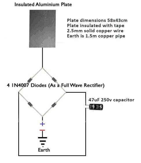
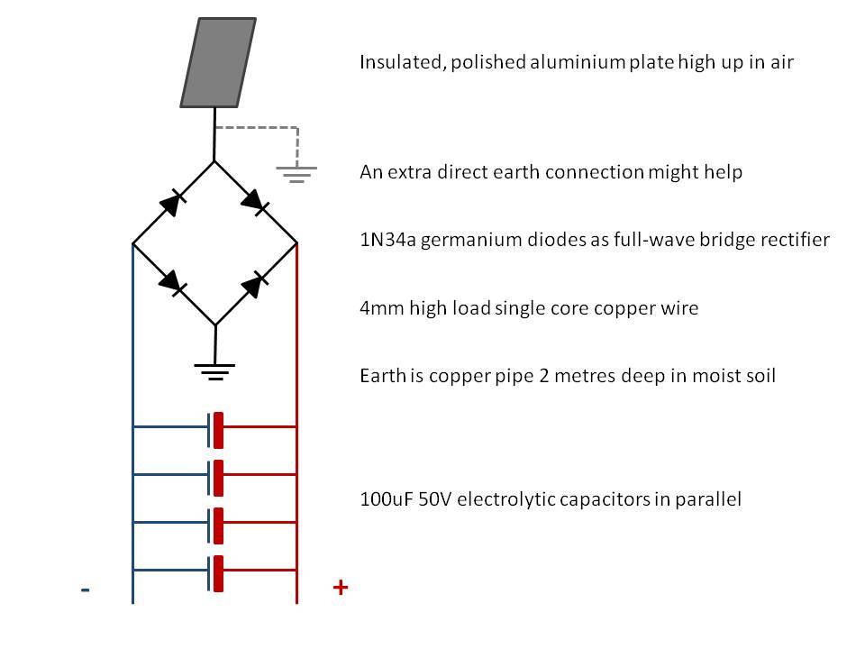
    Due to an old family friend's death I didn' go out of town yet. I ran the other four days of data for the solarwind/xray/voltage readings and they are pretty close. Not exact but close. I only have hourly readings and the correlation works out to plus or minus an hour. There are a few outliers that don't fit the theory - 5 out of 86.

    After thinkling about it I realised its probably not the xrays and gamma rays that I'm picking up in my plate but their interaction with the atmosphere probably releases secondary or tertiary charged particles that are being picked up by the elevated, insulated plate.

    More to think about.

    Comment


    • Some ideas

      Hey guys,

      I was able to generate 10v in 30mins using the following circuit based on the original Tesla Radiant Energy patent:


      However, I am very interested in building the Jes Ascanius circuit, because it promises to provide much more energy.

      The 200v 200nF capacitor is hard to find, because it does not exist. In fact, if you look closely at the pictures in the PJK book on page 9, chapter 7, you see that the capacitors used are actually 250v - 275v. Also, keep in mind that 200nF is the same as 0.2uF! So, a capacitor you could use is this one.

      I ordered all the parts and am going to build the system tomorrow, but I have some questions about the Jes Ascanius circuit. For example, I get that this setup diverts + energy waves into one half of the capacitors, while the - energy is stored in the other half of the capacitors. My question is: why not use a Full Wave Bridge Rectifier setup so you only need a single capacitor? This image shows what I mean:


      As you can see, I omitted the big 250v 0.2uF capacitors, because I don't really get why they are positioned before the diodes. Would be great if someone could explain that!

      Hope someone can answer my questions!

      Also, someone on an other forum mentioned that the 1N34a germanium diodes might be replaced by the much cheaper 1N5819 SCHOTTKY diodes ($0.34 vs $0.04!). I also purchased those, so I'll see how they perform.
      Last edited by Kregus; 09-02-2013, 03:03 PM.

      Comment


      • In prior threads there was a capacitor that wasmentioned to work fine that was ordered through Mouser with the part #80-R46KN3220JBM1K that are .60 each or in mutiples with reduced price. They are .22 uF 275V capacitors, they appear to be similar to your Newark caps.
        I commend your enthusiasm on this and as Jes states to use exactly what he says when it comes to how the circuit is laid out first then you can experiment with other formats after seeing it work as he suggests.

        Comment


        • Results of my experiments

          Hi guys,

          I have been testing numerous variables the past weeks regarding the Jes Ascanius Radiant collector and would like to share the results.

          Here is an image of one of my Jes Ascanius modules:


          The module consists of:
          • 2x 100uF 50V capacitors
          • 2x 0.22uF 250V capacitors
          • 4x 1N34a diodes


          My aerial is a polished, insulated aluminium plate (58x43cm) and an insulated metal plate (80x70cm) +- 5m from the floor and positioned in my attic. I use one 1.5m copper earth rod placed in moist soil as my earth.

          My initial setup used 12 SWG (+-2.5mm) solid core copper wire. However, Jes suggests to use 8 SWG (+- 4mm) solid core copper wire. I tested both, but the output of the aerial remained unchanged.

          However, adding the 80x70cm metal plate as a second aerial plate nearly doubled the output!

          Modules
          In the PJK book ch7 p12 it says the following:

          "With this arrangement a single module produces around 30 volts."

          Unfortunately, my results were significantly less spectacular. With one module I could generate 0.7 volts after 5 minutes. I also used a small buzzer, which was unable to make a sound from this captured energy.

          When I connected two modules, the voltage remained at 0.7 volts after 5 minutes, but the buzzer now did make a sound. I am guessing this is due to a higher amperage that was stored by using two modules instead of one.

          Finally, I connected three modules. The result: again 0.7 volts after 5 minutes, but the sound from the buzzer was now a bit longer and louder.

          Here you can see my three modules connected:

          Red: coming from aerial
          Black: to earth
          Green: plus
          Yellow: minus

          Diodes
          In tests with the original Nikola Tesla Radiant Energy collector patent, I found that simple 1N4007 diodes yielded far superior returns to both the 1N34a and 1N5819 diodes. Therefore I built one Jes Ascanius module where I replaced the 1N34a diodes with 1N4007 diodes. While I expected an improvement, only 0.4 volts was captured after 5 mins compared to 0.7 volts with the original design which uses 1N34a diodes.

          And while someone suggested that the 1N34a diodes could be replaced by 1N5819, all my experiments showed that this is not the case. Do not use the 1N5819 diodes for these aerial devices.

          Capacitors
          Again, while testing the Tesla patent I experimented with different capacitors. For example, a 47uF 250V capacitor collected 5.2 volts after 10 minutes, while a 4.7uF 250V capacitor yielded 10 volts in that same amount of time. I need to order some more of those capacitors so I can test them in the Jes Ascanius modules.

          Tesla Coil
          I also built my very first and very tiny Tesla Coil today from spare parts:


          The power supply and circuit is from a bug zapper, the secondary coil is made from magnet wire from an old television and the toroid is made from a golf ball covered with aluminium foil. It works like a charm and produces sparks of +- 1cm. Pretty impressive for a tiny 3v input and no tuning.

          But the reason I discuss this here, and one of the main reasons why I built a Tesla Coil, is because of one of Tesla's ideas to produce radiant energy by short uni-directional DC pulses (spark gap), running these pulses through a Tesla Coil with a pointy top, and then capture that radiant energy by pointing this Tesla Coil towards a grounded metal plate (see PJK book Ch5 P87). Both Tesla and Don Smith have proven this theory to be true, and so I wanted to test it.

          Since my Tesla Coil is tiny, I did not expect to see anything. But when I pointed the spike on top of my coil towards one of my aerial plates while the coil was firing, I witnessed a huge surge of energy on my multi meter! Remember, the sparks coming off my coil are only 1cm. However, when I aimed the coil at the plates the distance was about 10cm. I found this very, very interesting and wish I had a more powerful Tesla Coil to test this further.

          Here is an image of my Tesla Coil with the spike I aimed at a plate. The plate in this image is just to give you an idea and not my actual aerial plate.


          Next steps
          What I haven't tested yet is the extra earth rod, so this I will try next weekend.

          I would also like to test lower capacitance, higher voltage capacitors instead of the 100uF 50V capacitors in the original design just to see how that affects the energy collection.

          Also, I will try to charge a 1.5V battery with my Jes Ascanius setup.

          Finally, I want to make my Tesla Coil more powerful by connecting it to a 12V battery and tuning it (although it is very hard to find clear advice on how to calculate the amount of turns, the required capacitance etc.)

          Well, I hope this information is useful for others who are experimenting with this system! Please share ideas for improvement.

          Have a great day!

          P.S. I would like to charge a battery using this setup, but how? Would be amazing if someone could give me an idea for a way to discharge the modules once they reach a certain voltage.
          Last edited by Kregus; 09-10-2013, 09:46 PM.

          Comment


          • Comments on the Ascanius circuit

            Originally posted by Kregus View Post
            Hi guys,
            However, adding the 80x70cm metal plate as a second aerial plate nearly doubled the output!
            The Tesla patent states that the larger the elevated, insulated plate the more the system will deliver so your result is to be expected.

            In the PJK book ch7 p12 it says the following:"With this arrangement a single module produces around 30 volts." Unfortunately, my results were significantly less spectacular.
            Remember that this system is collecting energy from the environment so it is your environment that determines your results. In an earlier post in this thread Jes Ascanius said it works better at higher altitudes and dryer air (lower humidity) than it does at lower altitudes and higher humidity. You should keep track of the humidity when you take your readings. Can I ask your altitude above sea level?

            In tests with the original Nikola Tesla Radiant Energy collector patent, I found that simple 1N4007 diodes yielded far superior returns to both the 1N34a and 1N5819 diodes. Therefore I built one Jes Ascanius module where I replaced the 1N34a diodes with 1N4007 diodes. While I expected an improvement, only 0.4 volts was captured after 5 mins compared to 0.7 volts with the original design which uses 1N34a diodes.

            And while someone suggested that the 1N34a diodes could be replaced by 1N5819, all my experiments showed that this is not the case. Do not use the 1N5819 diodes for these aerial devices.
            The Ascanius circuit is just a voltage multiplier circuit except for one thing: the 1N34 diodes are also photodiodes which means they convert light to electricity somewhat like a photovoltaic panel. To get the real power between the plate and ground they need to be wrapped in electrical tape or mounted in an enclosure that blocks out the light. I suspect that is the difference you are seeing using different diodes. They will probably be much closer when you shield the 1N34's from light.

            Again, while testing the Tesla patent I experimented with different capacitors. For example, a 47uF 250V capacitor collected 5.2 volts after 10 minutes, while a 4.7uF 250V capacitor yielded 10 volts in that same amount of time. I need to order some more of those capacitors so I can test them in the Jes Ascanius modules.

            I would also like to test lower capacitance, higher voltage capacitors instead of the 100uF 50V capacitors in the original design just to see how that affects the energy collection.
            A capacitor voltage rating is just the maximum rated voltage at which it is guaranteed not to fail. It doesn't have much affect on the compacitor until you go over the specified voltage which will cause it to short out internally. Gross over voltage can cause them to explode. What you are seeing with the higher voltages and lower capacitance devices (and the buzzer also) is the rate at which the circuit is charging the capacitors. As the capacitor becomes more highly charged the voltage goes up. A smaller capacitance device charges faster given the same input.

            Typically, the lower the voltage rating the smaller the deivce and the cheaper they are. So to keep the cost down you want to use the smaller devices but with a sufficient voltage rating to prevent them from being damaged.

            P.S. I would like to charge a battery using this setup, but how? Would be amazing if someone could give me an idea for a way to discharge the modules once they reach a certain voltage.
            There are a lot of battery charging circuits on the internet but the critical determination is the chemistry of the battery. NiCad, lithium ion, lead/acid batteries all have different charging parameters. Outside of the parameters on the low side and you won't get a full charge and possibly no charge. Outside of the parameters on the high side and you can either shorten the life of the battery or possibly blow it up which is not a minor problem when dealing with acids and/or volatile chemicals like lithium. Also keep in mind that the charging volatge has to be higher than the battery voltage so you'll need a circuit to step up the voltage but if you step it up too much you'll damage the battery and possibly injure yourself and/or your equipment. So you need some kind of regulation to handle over volatges as well.

            Comment


            • Hi thx1138,

              Thanks for your in depth reply! I learned a lot from it.

              Originally posted by thx1138 View Post
              The Tesla patent states that the larger the elevated, insulated plate the more the system will deliver so your result is to be expected.
              You are absolutely correct. Just mentioned it to state that my tests confirm this as well.

              Originally posted by thx1138 View Post
              Jes Ascanius said it works better at higher altitudes and dryer air (lower humidity) than it does at lower altitudes and higher humidity... Can I ask your altitude above sea level?
              Hmm.. in that case the Jes Ascanius system might not be ideal for my situation. I live at sea level and the average humidity during my tests was 78%.

              Originally posted by thx1138 View Post
              the 1N34 diodes ... convert light to electricity somewhat like a photovoltaic panel. To get the real power between the plate and ground they need to be wrapped in electrical tape or mounted in an enclosure that blocks out the light.
              I quickly tested this by putting the system in an enclosure, and it indeed led to slightly more power. Still, if you say they convert light to electricity, I would assume that it is good to have them subjected to light in order for them to convert more light into electricity, but I guess I am missing the point.

              Originally posted by thx1138 View Post
              As the capacitor becomes more highly charged the voltage goes up. A smaller capacitance device charges faster given the same input. Typically, the lower the voltage rating the smaller the device and the cheaper they are.
              Thanks for this explanation! Makes sense now.

              Originally posted by thx1138 View Post
              There are a lot of battery charging circuits on the internet but the critical determination is the chemistry of the battery. NiCad, lithium ion, lead/acid batteries all have different charging parameters. Outside of the parameters on the low side and you won't get a full charge and possibly no charge. Outside of the parameters on the high side and you can either shorten the life of the battery or possibly blow it up which is not a minor problem when dealing with acids and/or volatile chemicals like lithium. Also keep in mind that the charging voltage has to be higher than the battery voltage so you'll need a circuit to step up the voltage but if you step it up too much you'll damage the battery and possibly injure yourself and/or your equipment. So you need some kind of regulation to handle over voltages as well.
              Great info! I will look into this some more. I have seen several battery charging circuits in the PJK book, for example the Alexkor system, but they often require some sort of spark gap. However, I have been unable to find the part which is mentioned several times in the book as a neon tube. If you or anyone else knows a supplier and/or part number, that would be greatly appreciated!

              By the way, I also created a second copper earth rod and connected it the way it is explained in the Jes Ascanius circuit; effectively as a short circuit. Unfortunately, this configuration no longer charged, but instead slowly discharged the capacitors.

              Comment


              • Diodes

                Originally posted by Kregus View Post
                Hi thx1138,
                I quickly tested this by putting the system in an enclosure, and it indeed led to slightly more power. Still, if you say they convert light to electricity, I would assume that it is good to have them subjected to light in order for them to convert more light into electricity, but I guess I am missing the point.
                The initial point was explaining why different diodes deliver different results. With the 1N34 diodes delivering power from light, the circuit will not deliver a steady output so storage will be required - nothing can be run from it directly. As you can tell from your buzzer the rate of charge is slow. That being the case, why go to all this trouble? Why not just use a photovoltaic panel which is proven technology that collects "radiant energy"?

                Hmm.. in that case the Jes Ascanius system might not be ideal for my situation. I live at sea level and the average humidity during my tests was 78%.
                I'm pretty sure that the lower elevation and higher humidity are why you are getting the lower voltages. I was going to go to some relatives' property in Colorado that is at 7000 feet (2133 meters)this summer to do some testing but they sold the property and I wasn't able to confirm that.

                I have some rural property where I did some testing over the last two weeks and regardless of the circumstances (I also have a suburban home where I've done some testing), the output varies widely just like wind or photovoltaics so I don't see anything really useful in this system. Sure, we can charge a battery with this circuit but that's possible with far less effort using known technologies.

                I guess there's something to be said for repurposing old electronic components and scrap metals but unless we have total societal collapse I don't see this system as useful. It would take acres of elevated plates to run a single home. I guess any reduction of dependency on power obtained from the grid would be a benefit but the only way I see this system as useful is if the entire roof of a house were built of insulated metal plates feeding a battery bank. All you're doing with that scenario is trading the money spent to purchase power from the grid for purchasing and maintaining batteries and control equipment.

                At least, that's my take after spending lots of time on this system so I'm redirecting my efforts to other systems.

                Comment


                • Hi,

                  This system has been my very first endeavor into the realm of radiant energy, so the fact that it captured even a tiny voltage has already been really exciting! Also, I've learned a lot about electronics by trying this out. Still, I agree with you that if someone wants to produce serious power it is probably better to focus on other systems. Although the tesla coil + receiver plate system described in my earlier post still seems like a viable option to generate significant power.

                  Comment


                  • Originally posted by Kregus View Post
                    Hi,

                    This system has been my very first endeavor into the realm of radiant energy, so the fact that it captured even a tiny voltage has already been really exciting! Also, I've learned a lot about electronics by trying this out. Still, I agree with you that if someone wants to produce serious power it is probably better to focus on other systems. Although the tesla coil + receiver plate system described in my earlier post still seems like a viable option to generate significant power.
                    Last year i wrapped a plasma globe in tinfoil and used that as an antenna
                    Ground was just the household earth as i live in a 3rd floor apartment
                    I had 4x Jes modules (not to spec, used OA90 diodes i think and the caps wernt to spec either)
                    The plasma globe drew 12W
                    I was able to blow a 5W automotive bulb on the output (nothing to show off about as the input was 12W anyway)
                    Never tried a bigger bulb.
                    The globe drew more power when i attempted to have a load on the output.
                    Thats about all i can tell you about my experiment.

                    Comment


                    • Radiant Energy

                      Originally posted by Kregus View Post
                      Hi,
                      This system has been my very first endeavor into the realm of radiant energy...
                      "Radiant energy" isn't really anything other than energy that is radiated. There is a lot of confusion on the issue and a lot of people make a case for Tesla's radiant energy work having been suppressed, hidden, etc. so it would be easy to get side tracked.

                      Here's the earliest quote I could find from Tesla where he uised the term "radiant energy":
                      “…streams resembling the cathodic must be emitted by the sun and probably also by other sources of radiant energy, such as an arc light or Bunsen burner.” That is from “Tesla’s latest Roentgen Ray Investigations”, Electrical Review, New York 28 No.17, May 22, 1896

                      So we can say that today's photovoltaic systems are an implementation of Tesla's radiant energy work.

                      His work went from there to X-rays to cosmic rays and eventually to atomic power. Keep in mind that nuclear materials were not regulated until the 1950's after it was shown that they could be used in nuclear weapons. In Tesla's day there were no controls whatsoever on nuclear materials.

                      I put together the attached document to identify what he meant by "radiant energy". Hopefully, it will help you avoid some blind alleys.
                      Last edited by thx1138; 01-03-2015, 02:00 AM.

                      Comment


                      • Originally posted by thx1138 View Post
                        "Radiant energy" isn't really anything other than energy that is radiated. There is a lot of confusion on the issue and a lot of people make a case for Tesla's radiant energy work having been suppressed, hidden, etc. so it would be easy to get side tracked.

                        Here's the earliest quote I could find from Tesla where he uised the term "radiant energy":
                        “…streams resembling the cathodic must be emitted by the sun and probably also by other sources of radiant energy, such as an arc light or Bunsen burner.” That is from “Tesla’s latest Roentgen Ray Investigations”, Electrical Review, New York 28 No.17, May 22, 1896

                        So we can say that today's photovoltaic systems are an implementation of Tesla's radiant energy work.

                        His work went from there to X-rays to cosmic rays and eventually to atomic power. Keep in mind that nuclear materials were not regulated until the 1950's after it was shown that they could be used in nuclear weapons. In Tesla's day there were no controls whatsoever on nuclear materials.

                        I put together the attached document to identify what he meant by "radiant energy". Hopefully, it will help you avoid some blind alleys.
                        Wow thx1138... that is the very best explanation I have read so far about radiant energy! It all makes so much more sense now.

                        Thank you so much for creating that document; everybody who is even remotely interested in radiant energy, or Tesla's way of thinking, should definitely read it!

                        Comment


                        • Hi Kregus

                          Thanks for posting your experiments.
                          I build the Jes Ascanius circuit some time ago but lost interest
                          In it, after reading your posts decided to experiment some more
                          My unit is identical to yours even down to the red .2uf caps
                          I went and set it up in my living room on a coffee table, my plate
                          Arial (an old computer side cover) is about 1m of the ground and
                          the earth is my house earthling rod. The strange thing is this I get
                          better results now then when I had my plate 5m high. I get
                          360 Millie volts when my multimeter is permanently connected and
                          670 Millie volts when I measured it 10min after I disconnected
                          the multimeter I also found that it is very sensitive to almost any
                          movement around it and to florescent lightning (with the light on
                          it goes even higher), if I move the plate by even 1cm i get a
                          voltage drop.

                          I would also like to try and charge batteries with it but am thinking
                          In trying to connect a joule ringer circuit to this for charging batts.
                          Don’t know if it will work but I will try anyway.

                          Thanks again and I hope you keep on posting your results
                          Best
                          Johan.

                          Comment


                          • Hi Thx1138

                            Thank you for sharing your knowledge so freely and that
                            PDF is very informative you have made it much easier to
                            Understand radiant energy.

                            Best regards
                            Johan

                            Comment


                            • my project

                              Hi, I tried to use the same pattern of Jes. The antenna I made it with a gutter about 30 meters high and the earth I did with the 220​​-volt home. In this way I get a little more than 2 volt. It 's normal? should not I get more?

                              Thank you

                              Comment


                              • Jes Ascanius

                                Originally posted by Bizzy View Post
                                Good morning
                                In looking over the Jes Ascanius radiant collector as found at

                                http://www.free-energy-info.co.uk/Chapter7.pdf

                                I have a question I thought someone here on the forum might be able to answer. In the link provided when it describes the aluminum plate it doesn't say that it should be insulated as Tesla mentioned. So my question is should the plate be insulated or not?
                                Thanks
                                Bizzy
                                Insulate the Aluminum plate. I used wood.

                                Comment

                                Working...
                                X