The Camp David Antenna (2) (2 of 2)
(VI) Alexanderson also developed the co-linear array for the R.C.A. H.F. maritime mobile service (KPH). The co-linear array is an alternating sequence of half wave radiators and of phase reversing stubs. The result is that all half wave radiators operate in phase conjunction. Where it is all the radiators of the Type A are in PARALLEL, those of the co-linear are all in SERIES. Both share the PHASE UNISON CONDITION and are a concatenated sequence of networks and elements, the fundamental Alexanderson principle. The co-linear is a harmonic array and operates not only at its fundamental frequency but also at the third harmonic of that frequency. Operation on the fifth and seventh harmonics is possible but is of poor performance. There is the beginnings of a “frequency independent” antenna. This is an objective in the “Bolinas Antenna”.
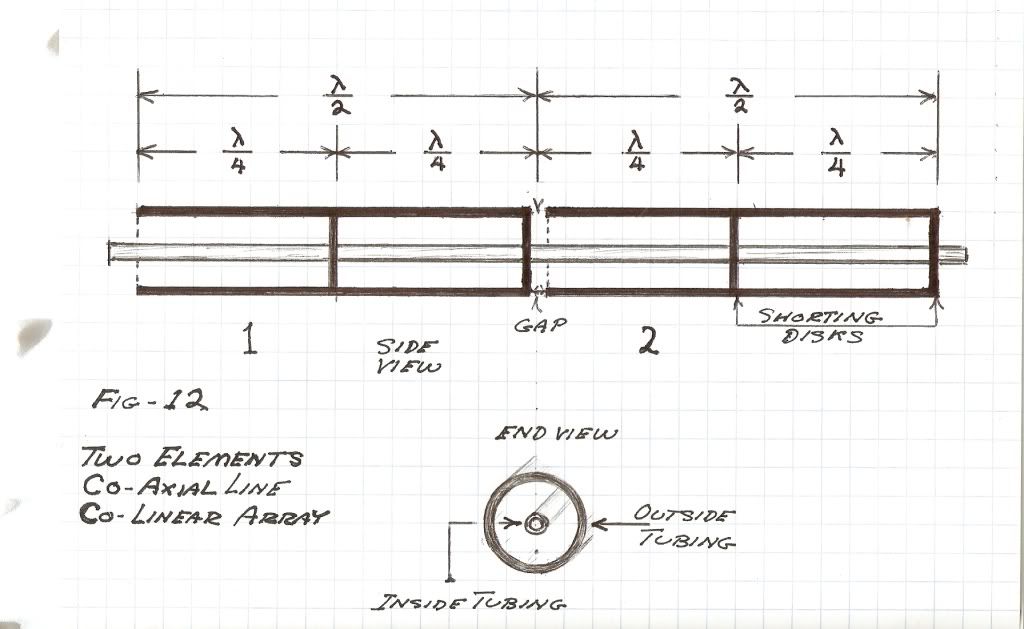
The co-linear array developed into the most common antennae in use today, Fig (12). This is the co-axial vertical phased array and it has extensive application in the land mobile V.H.F. and U.H.F. Services, 30 megacycles to 1000 megacycles. With some minor changes this antenna arch-form will serve as the seed element for the “Bolinas Antenna”.

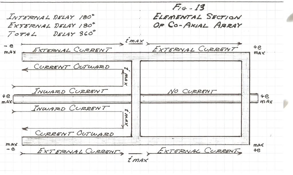
(VII) The element of the co-axial co-linear is shown in Fig (13). This element operates in two different modes at the same time. One mode is the transmission line mode, the other mode is the antenna mode. In the transmission line mode the electric field is confined to the counter-space between the element conductors, nothing gets out. In the antenna mode the electric field is spatial, external to the conductors. The external field is subject to the hysteresis of the Aether and this gives rise to a “radiation resistance”. This is discussed in “Velocity of Propagation of The Electric Field” from the 1920 Transient Phenomena book by C.P. Steinmetz.

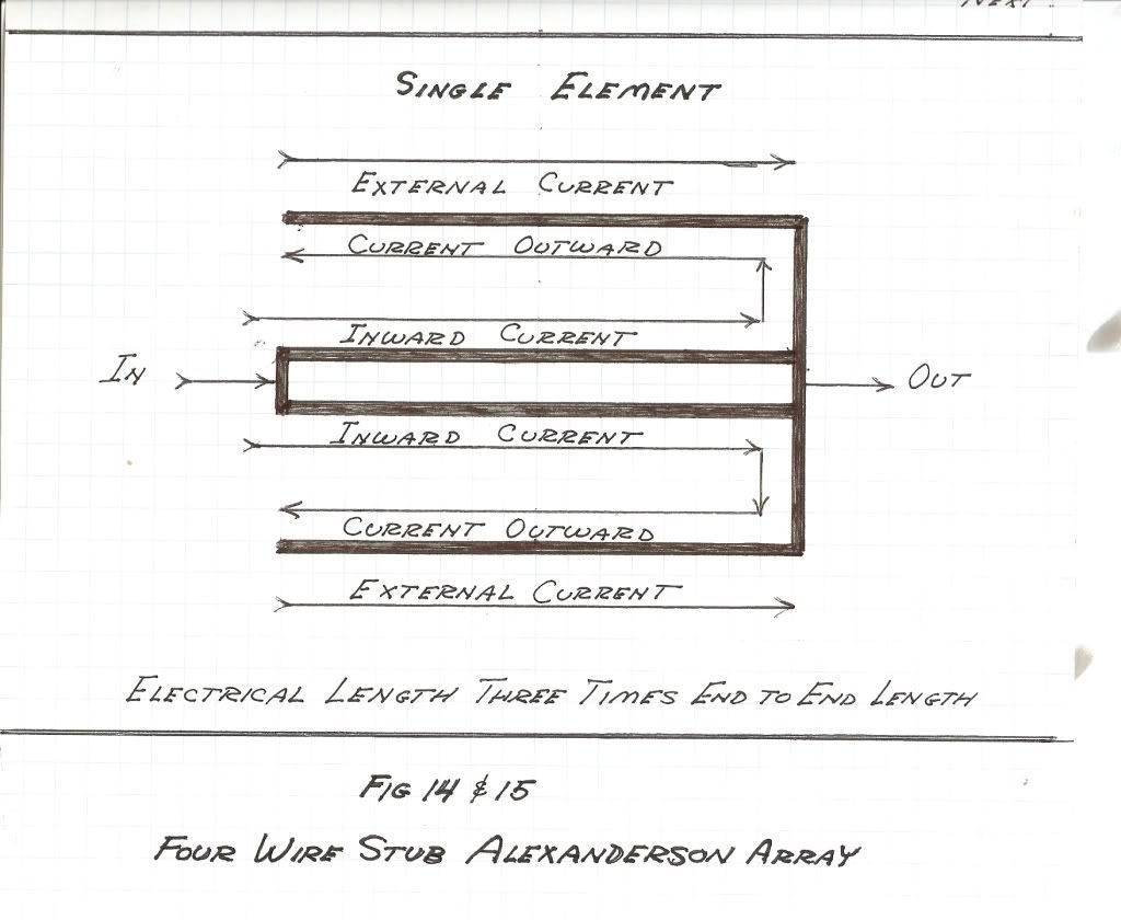
Here exists the loading section and the line section sharing the same geometric structure. It is a dual mode transmission line. To decrease the radiation loss and increase the reactance of the co-axial element is modified to that shown in Fig (14). This will be the arch-element.

Fig (14)
(VIII) The end to end transmission delay of this element is now three times that of an equivalent single mode section. This element is hereby three times the electrical length of a single mode section. Because only one third of the propagation path gives rise to an external electric field its radiation resistance is only one third that of a single mode section. Also the wavelength is shortened by a factor of three, and the effective end to end velocity of the element is one third the luminal velocity of the dielectric in which the element exists. Hence a concatenated sequence of these elements establishes a “slow wave” structure of reduced radiation losses. The effective wavelength is now three times that of the end to end length of the concatenated sequence. For example a sequence of N elements one twelfth wavelength end to end has an effective length of one quarter wave. Hence this “array” is well adapted to confined antenna situations. Here derived is a basic Alexanderson multiple loaded array for the high frequency band, Fig (15).

Fig (15)
Break, more to follow
DE N6KPH
Table 1, Fig (1)
19 Gauge Toll Cable Pair
2R = 88 ohm / mile
2L = 1 milli-henry / mile
2G = 5 micro-siemens / mile
2C = 0.054 micro-farad / mile
(VI) Alexanderson also developed the co-linear array for the R.C.A. H.F. maritime mobile service (KPH). The co-linear array is an alternating sequence of half wave radiators and of phase reversing stubs. The result is that all half wave radiators operate in phase conjunction. Where it is all the radiators of the Type A are in PARALLEL, those of the co-linear are all in SERIES. Both share the PHASE UNISON CONDITION and are a concatenated sequence of networks and elements, the fundamental Alexanderson principle. The co-linear is a harmonic array and operates not only at its fundamental frequency but also at the third harmonic of that frequency. Operation on the fifth and seventh harmonics is possible but is of poor performance. There is the beginnings of a “frequency independent” antenna. This is an objective in the “Bolinas Antenna”.
The co-linear array developed into the most common antennae in use today, Fig (12). This is the co-axial vertical phased array and it has extensive application in the land mobile V.H.F. and U.H.F. Services, 30 megacycles to 1000 megacycles. With some minor changes this antenna arch-form will serve as the seed element for the “Bolinas Antenna”.

(VII) The element of the co-axial co-linear is shown in Fig (13). This element operates in two different modes at the same time. One mode is the transmission line mode, the other mode is the antenna mode. In the transmission line mode the electric field is confined to the counter-space between the element conductors, nothing gets out. In the antenna mode the electric field is spatial, external to the conductors. The external field is subject to the hysteresis of the Aether and this gives rise to a “radiation resistance”. This is discussed in “Velocity of Propagation of The Electric Field” from the 1920 Transient Phenomena book by C.P. Steinmetz.

Here exists the loading section and the line section sharing the same geometric structure. It is a dual mode transmission line. To decrease the radiation loss and increase the reactance of the co-axial element is modified to that shown in Fig (14). This will be the arch-element.

Fig (14)
(VIII) The end to end transmission delay of this element is now three times that of an equivalent single mode section. This element is hereby three times the electrical length of a single mode section. Because only one third of the propagation path gives rise to an external electric field its radiation resistance is only one third that of a single mode section. Also the wavelength is shortened by a factor of three, and the effective end to end velocity of the element is one third the luminal velocity of the dielectric in which the element exists. Hence a concatenated sequence of these elements establishes a “slow wave” structure of reduced radiation losses. The effective wavelength is now three times that of the end to end length of the concatenated sequence. For example a sequence of N elements one twelfth wavelength end to end has an effective length of one quarter wave. Hence this “array” is well adapted to confined antenna situations. Here derived is a basic Alexanderson multiple loaded array for the high frequency band, Fig (15).

Fig (15)
Break, more to follow
DE N6KPH
Table 1, Fig (1)
19 Gauge Toll Cable Pair
2R = 88 ohm / mile
2L = 1 milli-henry / mile
2G = 5 micro-siemens / mile
2C = 0.054 micro-farad / mile
 I can't say 100% for sure it's an organised disinfo group, but highly suspicious behaviour going on there.
Comment