Announcement

Collapse
No announcement yet.

Eric P. Dollard

Collapse
This topic is closed.
X
This is a sticky topic.
X
X
 
  • Filter
  • Time
  • Show
Clear All
new posts

  • Notes on Tesla Transceiving

    I have just been given the opportunity to view the E.F. forum by a passerby in the "Anarchist Cafe" here in Lone Pine. I am very pleased with the experimental efforts that have taken place with the Tesla Transformer. Also the bus station toilets have been cleaned out and are ready for a new load.

    Geometric Algebra has basically duplicated the Tesla Colorado Pri:Sec setup in a scaled down form. His effort is quite scientific and thus helpful. Dr Green actually constructed exactly what I had specified, how extraordinary!
    The effort however has fragmented into three incongrous channels,

    (1) Eric Dollard
    (2) C.R. Magic
    (3) T.M.T. Replication

    This is not the best thing to happen, one hand knows not the other hand. Most of the productive experimental effort is found on channel (2). Two important engineering prospects result:

    (I) A global network of synchronous Tesla Telluric Transmitters and Receivers
    (II) An A.M. broadcast repeater using the Tesla Transformer to bring DX A.M. stations to isolated distant communities, a passive system of rebroadcast.

    Do not forget to involve the F.C.C., they do not like being left out of things "radio" and actually they are looking for a bit of fun also! Experimental work is allowed on 400 Kc/sec the Industrial, Scientific, and medical allocation.

    On channel (3) of Farmhand, Dr Green has a finished unit. Now some response curves and magnification ratios of this would be nice on the forum. This is science in action. However on this channel my warnings about transmitting on the A.M. band are ignored. The F.C.C. also thinks its fun is to ream out A-holes, so let us see how long it takes for them to show up. Spark Gap transmission on the A.M. broadcast band is a great way to invite the F.C.C. to your home!

    I myself have no interest in fighting in Farmhand's sandbox, but it will be instructive to see how long it takes to get in hot water with the government. It is so easy in today's world. (911)

    Remember, maximum power is 100 milliwatts, it's the law! For more power a push-pull dual counter-wound transformer pair on 400 Kc/sec is legal. Drive around your home town with an A.M. radio and see how far you A.M. signal travels, you may be shocked at the distance. Report your findings on the forum for others to see, science in action.

    Break more to follow,

    73 DE N6KPH
    SUPPORT ERIC DOLLARD'S WORK AT EPD LABORATORIES, INC.

    Purchase Eric Dollard's Books & Videos: Eric Dollard Books & Videos
    Donate by Paypal: Donate to EPD Laboratories

    Comment


    • Originally posted by T-rex View Post
      I have just been given the opportunity to view the E.F. forum by a passerby in the "Anarchist Cafe" here in Lone Pine. I am very pleased with the experimental efforts that have taken place with the Tesla Transformer. Also the bus station toilets have been cleaned out and are ready for a new load.

      Geometric Algebra has basically duplicated the Tesla Colorado Pri:Sec setup in a scaled down form. His effort is quite scientific and thus helpful. Dr Green actually constructed exactly what I had specified, how extraordinary!
      The effort however has fragmented into three incongrous channels,

      (1) Eric Dollard
      (2) C.R. Magic
      (3) T.M.T. Replication

      This is not the best thing to happen, one hand knows not the other hand. Most of the productive experimental effort is found on channel (2). Two important engineering prospects result:

      (I) A global network of synchronous Tesla Telluric Transmitters and Receivers
      (II) An A.M. broadcast repeater using the Tesla Transformer to bring DX A.M. stations to isolated distant communities, a passive system of rebroadcast.

      Do not forget to involve the F.C.C., they do not like being left out of things "radio" and actually they are looking for a bit of fun also! Experimental work is allowed on 400 Kc/sec the Industrial, Scientific, and medical allocation.

      On channel (3) of Farmhand, Dr Green has a finished unit. Now some response curves and magnification ratios of this would be nice on the forum. This is science in action. However on this channel my warnings about transmitting on the A.M. band are ignored. The F.C.C. also thinks its fun is to ream out A-holes, so let us see how long it takes for them to show up. Spark Gap transmission on the A.M. broadcast band is a great way to invite the F.C.C. to your home!

      I myself have no interest in fighting in Farmhand's sandbox, but it will be instructive to see how long it takes to get in hot water with the government. It is so easy in today's world. (911)

      Remember, maximum power is 100 milliwatts, it's the law! For more power a push-pull dual counter-wound transformer pair on 400 Kc/sec is legal. Drive around your home town with an A.M. radio and see how far you A.M. signal travels, you may be shocked at the distance. Report your findings on the forum for others to see, science in action.

      Break more to follow,

      73 DE N6KPH
      Hi Eric, Since you mention me and the government and A-Holes I'll reply.
      I don't live in the U.S. of A the FCC has nothing on me. Your warning may
      have been ignored by others but not by me, it just doesn't bother me, if
      someone complains I will stop. Lots of people have resonant transformers and
      get no trouble.

      Right from when I started to experiment with resonance I maintained the view
      that spark gaps were not the way to go and I realized very quickly that I
      wanted to make continuous waves, which I don't seem to be able to do with
      a spark gap. No matter. I'm in no hurry to do what I want to do, there are
      other ways I believe.

      People kept coming to me and saying Tesla stuff "MUST" have a spark gap. I
      disagreed. I already know that the signal goes a long way even with my low
      voltage coils that were all wrong, I had a co-inhabitant come home and tell
      me he picked up my noise from a couple of klm's away or so when my setup
      was making a lot of noise that is. Once it was tuned it didn't cause him bother.

      Cheers

      Comment


      • Originally posted by T-rex View Post
        ....Two important engineering prospects result:

        (I) A global network of synchronous Tesla Telluric Transmitters and Receivers
        (II) An A.M. broadcast repeater using the Tesla Transformer to bring DX A.M. stations to isolated distant communities, a passive system of rebroadcast.

        73 DE N6KPH
        (I) Is this kind of like what Tesla envisioned in his world system?
        (II) Are we limited to AM because of regulations or is there another reason?


        Anyone.

        Comment


        • Notes on Tesla Transceiving 2

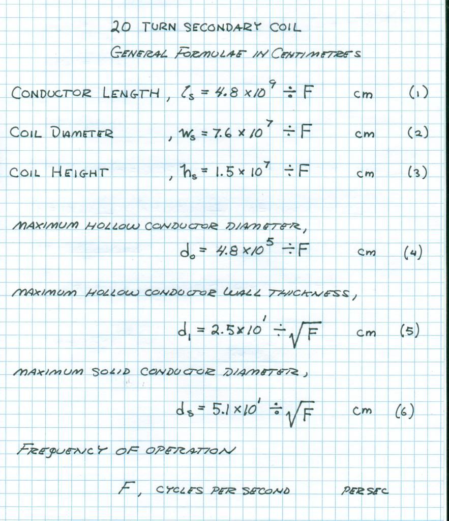
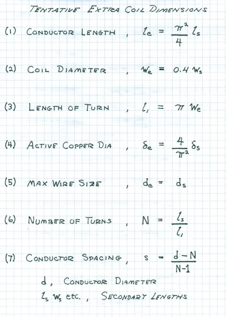
          You are all playing with my first fully mathematical design, no books, no experiment, just a pad of paper in the seat of my Corolla sitting in between giant rocks, one 14,500 feet high! And you all have shown it to work. It must be noted here the given extra coil is a compromise, Colorado Unit will not completely scale down to broadcast band without excessive turns of fine wire on a tiny extra coil.

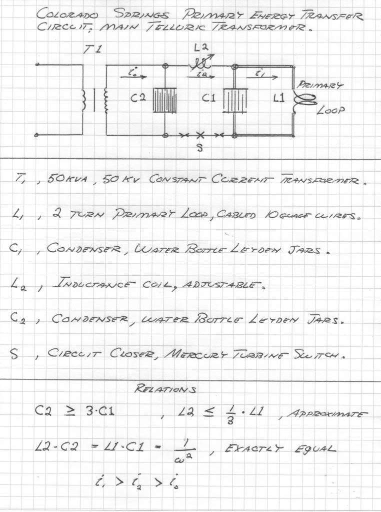
          Note that a primary condenser is a must and it must match the KVar of the primary coil. Equal surfaces or equal weight for coil and condenser, a good "Rule of Thumb". There must be no breaks, gaps, etc between the coil and condenser, NONE! Tesla says this in his refined designs. (Fig 1)

          The final setup at Colorado Springs, the FINAL ONE, should go on forum;

          1) Coil heights, widths,
          2) Number of turns,
          3) Wire Gauge, and number of wires in primary bundle,
          4) Length of wire in secondary and extra coils,
          5) Operating frequencies,
          6) Primary condenser connections and auxilliary devices in with the primary system

          This is of extreme importance, do not get hung up on test coils, un-related experiments, or early transformer construction, we want ONLY his finished product known to be his final perfection for earth resonance. Can anyone do this and not put out distractive parts of Tesla's notebook? Let us see. Also a compendium of everyone's unit is important here.

          In conclusion I am very happy to see how all this grew out of a few pages of equations scribbled in the front seat of my Corolla to an International Experimental Effort. From my first efforts in 1980 at RCA to a final design equation in 2012. It was long path to follow.

          Soon my name in this will be forgotten by everyone and some will claim it their own idea, then I can join Tesla in oblivion. As Peter Lindemann expressed when asked about the widespread use of my material without my knowledge or consent, that Eric is just an A-hole so no one wants to involve him in his own discoveries. My multi-wave oscillator antenna is in wide use through Lindemann, Borderland, etc and I get nothing. Well it is just a small bit of the over 50 Kilobux Borderland embezzled from me. Tom Brown told me that I owed it to (Her), that, (She), needed it more than I did. Well (She) is dead now and the money is spent. The notes, record, equipment of my work is long gone, good buddy Tom Brown. It serves Al-Gora well that all the records of my RCA solar-terrestrial work vanished, so who is helping who?

          When I undertook providing this forum with the means of duplicating a part of Tesla's work, this in the form of the C.R.I., it was tacitly assumed that it would be used responsibly, no weapon development, no interference to other services, only legal and responsible use. This requirement has been violated. Moreover flouted attitudes of punk personalities serve to negate my own interest in making my efforts known to this forum, or anyone at all. It in no way serves my own interest to provide any info here, and I am in fact serving as a prostitute on this forum, spreading my legs for a few sheckels to keep the car running. You can rest assured once a coyote is not pinned down it will just vanish into invisibility.

          73-DE-N6KPH

          Note Jake,
          1) This is the starting point of the "World System" (on 400 Kc!), a "Ham radio" net.
          2) A.M. stations are pilot signals for the experimenter, this makes it easy and legal to work with Tesla Systems, a receive only development.

          SUPPORT ERIC DOLLARD'S WORK AT EPD LABORATORIES, INC.

          Purchase Eric Dollard's Books & Videos: Eric Dollard Books & Videos
          Donate by Paypal: Donate to EPD Laboratories

          Comment


          • Originally posted by T-rex View Post
            no interference to other services, only legal and responsible use. This requirement has been violated.
            I believe this is my fault since apparently I'm the only one to have built a coil using the calculations and applied a spark gap to it. I just figured that the coil being so small and using such low power input it wouldn't interfere with anything, also doing experiments generally at 1-6am and living in a small village miles away from civilisation I didn't expect to be causing anyone any problems. It should also be noted that this small coil isn't built to receive the local radio station so it's not in direct opposition to any known service.

            Is there any situation in which we are "allowed" to use spark gaps for power transmissions in this day and age? And would a Faraday cage be of any use to minimise any potential disruption in the area since it's the ground currents we're more interested in?

            Anyway I believe the objective has now split into the following:
            1: Build Telluric receiver for local radio station (and DO NOT transmit using this coil)
            2: Build 2nd transmitter/receiver for 400kHz as combined global experimental effort?

            And then I assume based on the diagram spark gaps would be allowed on this channel? However Ofcom (UK equivalent of FCC) reckons 325-405kHz is used for Aeronautical radionavigation

            RA365 - United Kingdom Table of Radio Frequency Allocations 9kHz - 105GHz


            Dr Green has a finished unit. Now some response curves and magnification ratios of this would be nice on the forum.
            I can't do any of this until I get/make an oscillator that will do up to 3.67MHz+ of the coil. The TL555CP max is 3MHz so that will be pushing it a bit and that's about the only material I have at hand that I know of, so if anyone could advise whether or not crystal oscillator sourced oscillators output frequency can be varied/tuned slightly it would be appreciated. I have 1961 and 1963 editions of Radio Amateur's Handbook so the circuit diagram of what I need should be there as far as I understand all this, someone please correct me if I'm wrong, so all I need to know before I buy any crystals is can I use it for this purpose? If not can anyone suggest any DIY/cheap alternatives?
            http://www.teslascientific.com/

            "Knowledge is cosmic. It does not evolve or unfold in man. Man unfolds to an awareness of it. He gradually discovers it." - Walter Russell

            "Once men died for Truth, but now Truth dies at the hands of men." - Manly P. Hall

            Comment


            • Originally posted by T-rex View Post
              Soon my name in this will be forgotten by everyone and some will claim it their own idea, then I can join Tesla in oblivion. As Peter Lindemann expressed when asked about the widespread use of my material without my knowledge or consent, that Eric is just an A-hole so no one wants to involve him in his own discoveries. My multi-wave oscillator antenna is in wide use through Lindemann, Borderland, etc and I get nothing. Well it is just a small bit of the over 50 Kilobux Borderland embezzled from me. Tom Brown told me that I owed it to (Her), that, (She), needed it more than I did. Well (She) is dead now and the money is spent. The notes, record, equipment of my work is long gone, good buddy Tom Brown. It serves Al-Gora well that all the records of my RCA solar-terrestrial work vanished, so who is helping who?
              Would be silly if it wasn't so sad.

              Eric lost all his equipment on his own. I had nothing to do with it, in fact we preserved as much as possible at borderlands at the time (the pancake coils), those couple bits he didn't run off with behind our backs while we were working to help him keep his research going. But it all went back to Eric when he resurfaced from one of his angry-at-everyone disappearance acts. All files of Eric's which were provided by him for safe-keeping were copied and given back to him (we published the ones he wanted us to, now essential research material). He apparently dealt with borderlands after I moved overseas in 1995 so not sure about anything past that.

              No money was withheld from Eric, in fact everybody went out of their way to make sure he could keep his work going, despite being chastised persistently for not doing enough... because we all appreciated his rugged character and true genius. All Josh Reynolds' funds to Eric went through another organization on the East Coast and never through borderlands.

              A kind Mexican industrialist did pay some funds through borderlands, and through agreement with Eric 10% was taken out for administration costs and 90% put into a lab account which went to rent, equipment, and whatever else Eric spent it on. When this industrialist called Eric to see what had been done (this was during the cosmic induction generator building phase circa 1988) he told the gentleman that nothing was finished as he never got enough money to do anything right. Great way to thank a kind benefactor and stop the flow of funds!

              As for the MWO antennas, they were etched circuit board material, masked and gold plated. Eric could make some today, he is the one that in 1986 said to give the information out freely for people to use. Nobody is stopping him from making and selling his design. Borderland made a small run in 1986, which Eric got some of. Can be remanufactured any day of the week that the circuit board companies are operating. No conspiracy here.

              It appears Eric needs these blame-fantasies to remain a bitter refugee from society without accepting his own failings in the matter. Perhaps this characterological armoring drives his genius, that is my best surmise from experience.

              Having said all that, none of this is germane to proceeding with the engineering work. But I'm over being defamed on false and misleading info. I've recently donated money to Eric to help, even while he was actively defaming me, never got a thanks or any response at all. I've scanned old lab pictures and posted them to the n6kph yahoo list to help researchers. And I still think very highly of Eric even if he needs to continually blame myself and others for his self-inflicted problems. I learned much from him and appreciate all the incredible information he has made available to others. It is very heartening to see all the interest and work around the world right now on Eric's ideas, 25 years ago it was hard to get anybody's attention.

              I truly hope Eric does well and can get back to his research sometime. With proper funding and a good lab he can be the greatest genius of the 21st century. No matter what, he has give us priceless gems of knowledge in the painful process.

              Tom Brown
              thomas@thomasbrown.org

              Comment


              • Using these:


                F = 3670000 cycles/sec

                Secondary
                Height = 4.08cm
                Diameter = 20.7cm
                Number of turns = 20
                Wire = 13 +/- metres 26 SWG (thin wire issues resulting in slight octagon shape therefore reduced length, estimated actual length = approx 12.92 metres)
                Approx 18.9 grams of copper in coil

                Extra coil
                Height = 8.28cm
                Diameter = 8.28cm
                Number of turns = 126
                Wire = 32.27 metres 26 SWG (advisable not to use thicker wire otherwise no room on coil frame, impossible to space 126 turns evenly as is)

                Margin of error between calculated and measured frame dimensions after construction = <0.5mm

                Primary
                2 turns, not flat spiral
                Wire = 2 x 20 SWG + 24 SWG parallel wound

                Tests results = Forthcoming
                Last edited by dR-Green; 05-14-2012, 07:42 AM.
                http://www.teslascientific.com/

                "Knowledge is cosmic. It does not evolve or unfold in man. Man unfolds to an awareness of it. He gradually discovers it." - Walter Russell

                "Once men died for Truth, but now Truth dies at the hands of men." - Manly P. Hall

                Comment


                • Don't have the necessary size of copper for the primary on the AM RF range. instead went with a 4Mhz fq and built a CW/CCW pair. started with the basic equations Eric posted and 'adjusted' some details to factor in the HF. I'll be putting together a document and mailing it off to Eric, it may be of use to him or not.

                  I'm going to be moving onto another area of research in the same vein but from a different approach. electrostatic plasma optics. It's been a very worthwhile to detour here as it has helped with my own research on the dielectric.

                  couple pics hopefully should load. 4v 30 milliamp LED lights brightly near the designed frequency, loads more tuning needed but all in all it was faster than i anticipated in getting it to work. the CCW extra tuned quickly while the CW has been difficult, very strange.

                  no ground to earth, all chassis ground to the OSB that has a aluminum foil backing and wrapped in 3mil plastic. the foil back is the shared capacitive ground to the coils.
                  Attached Files

                  Comment


                  • dR Green,

                    The disruptive discharge, wrongly called "spark" is not for transmission work. This oscillatory transient wave is for Aether work. Today this is reduced to plasma work. Here is where to find the Tesla X-Ray research. See E.P. Phenomena of the Anode and Cathode." Transmission applications utilize continous waves which may be complex harmonic formsas well as simple harmonic functions called "Sine waves". Individualized harmonic structures gave "channelization" to the Tesla Transmission Plan, this analagous to carrier telephone multiplex systems. Tesla called this "Individualization".

                    It is very unfortunate to hear that you live in the U.K. This is the land of George Orwell. His 1984 was reversal of 1948, his idea of the birthdate of human hell on earth. U.K. is very unfriendly to radio, actually it despises it. I would be imprisoned for my military Corolla, and they would destroy the car. But here in America the car is a registered civil defense asset to the Sheriffs Office.

                    Quite a disparity would you not say. It will be here in America soon, we fought this at Camp David. In the desert it was said "First your guns, then your radios", the united way.

                    I grew up in the world of 300 Kc to 3000 Kc, at one time it was a vibrant band of aeronautical and maritime activity. This now is mostly a wasteland and the broadcast band is now no better than C.B. radio. The maritime service allocations near 500 Kc are now open for an engineering development of an improved system for the transmission and reception of signals for ships at sea. This was the mission set upon me by the Radio Corporation of America. This is one place to start a Telluric Broadcast Beacon to ships at sea, it is licenseable.

                    The other angle to take is Industrial, Scientific, and Medical. Every country uses induction or dielectric heating equipment. It was my job in Los Angeles to rebuild the 10-100 Kilowatt units and in some the stray fields were scary. These often use power oscillator of poor frequency stability thus have their own allocations often away from other services. In America one frequency is 400 Kilo-cycles. However these frequencies are not intended for communication purposes, only its scientific development.

                    Therefore, in order to begin one must directly contact, in person if possible, the radio commisar of the country which a setup is to be established. Also someone must have a commercial radio license in most cases.

                    Finally there is the 160 meter Ham band but the Ham band is like the city Greyhound station, Bengal. Most Hams today are walkie-talkie yac-yackers, they have no interest in radio so that leaves 160 meters open for experimentation.

                    Ultimately it is the International Telecommunications Union, Geneva, that decides and dictates radio law. Radio is government controlled in accordance with I.T.U. guide lines. The principle countries in which Telluric Transmission Systems are culturally relevant is USA, UK, and "down under."

                    With these considerations the first step is post the basic I.T.U. guidelines for frequency allocations. Then post the band allocationsfor USA, UK, and Japan. This data in one place would be very instructive.

                    73 DE N6KPH
                    SUPPORT ERIC DOLLARD'S WORK AT EPD LABORATORIES, INC.

                    Purchase Eric Dollard's Books & Videos: Eric Dollard Books & Videos
                    Donate by Paypal: Donate to EPD Laboratories

                    Comment


                    • A quick search yielded the following...

                      ITU Website

                      US Frequency Allocation Chart

                      UK Frequency Allocation Chart

                      Japan Frequency Allocation Chart

                      Hopefully that is of some help.

                      Comment


                      • Wire diameter

                        Dr-Green
                        What is the actual wire diameter of the #26 SWG wire with insulation? With Enamel wire you can wound 20.3 turns per centimeter, or on 8.28 cm length approximately 168 turns close wound. But you only need 126 turns, so you have about .008" space between the turns with enameled wire. Indeed very difficult to maintain.

                        Comment


                        • Originally posted by purelyconstructive View Post
                          A quick search yielded the following...

                          ITU Website

                          US Frequency Allocation Chart

                          UK Frequency Allocation Chart

                          Japan Frequency Allocation Chart

                          Hopefully that is of some help.
                          Just a quick reminder for anyone who posts documents or links. Because Eric is not computer savvy, it makes it MUCH easier for him if, when possible, the information contained in links is posted here in the thread if space allows. It ensures Eric will see the material. Anything outside this thread is "Babylon". Also if you can, when you post pictures try to post them using an online photo hosting service, so Eric (or anyone else) doesn't have to be logged in to see the pictures. This is a common complaint from Eric, that he can't see the material. Often times he is not logged in when viewing the thread from a coffee shop. Thank you for locating the material purelyconstructive
                          Please help support my indiegogo campaign: Cosmic Induction Generator

                          Comment


                          • Tesla Colorado Springs Notes Detail:

                            Hello all, my first post here and have been active at 'n6kph' and the 'Crystal Radio Magic'.
                            Eric has asked for the detail from the CSNotes which I have collated and presented at other sites as I have also spent considerable time with these important Notes:

                            Tesla Colorado Springs Notes detail:
                            As indicated by Eric Dollard.
                            These data I have either obtained from the Notes or from my own calculation/research.
                            Please let me know if you have criticisms or corrections
                            In Tesla's Inductance calculations you can change his 'cm' (centimetre) to read uH (microhenry).

                            Primary:
                            Consisted of two 1.5" 38mm cables which were joined together as one.
                            L = 32.5uH (my calc)
                            Diameter = 49.25' 15.0114 metres This from both William Wysock and the Beograd Museum data
                            Length = 154.723' 47.16m
                            Frequency = 59khz

                            Question arises here as to where they were exactly.
                            Are they immediately under the secondary on the same frame or under the ground?
                            I notice the front of the building has been raised above the normal terrain by about a foot and consider they may have been placed under the floor into the earth below.
                            They were said to have had metal bars attached to them at intervals and this suggest something different than just an open air coil.
                            It was well known that the earth surrounding the site was electric with sparks coming from footwear and horses hooves.
                            A requirement of the Magnifying Transmitter was a solid ground interface.

                            Secondary:
                            Began with 37 turns and finally reduced to 17 and this data is for the final figure where the Third Coil was in place.
                            L = 9.57mH
                            Diamter 49.25' as above for Primary.
                            Length 2630.3' 801.7m
                            Frequency 96khz
                            K = 0.6

                            Third or Extra Coil:
                            100 Turns (98 turns of 6 awg, 2 turns of 10 awg rubber covered)
                            L = 20.22mH
                            Wooden Frame - must be square:
                            Diameter = 8'3" 2.52m
                            Height = 8' 2.44m
                            Length = 2591.8' 790m
                            Frequency 96.85khz, second harmonic

                            Smokey

                            The Inductance calculations are mine.
                            Reference to 'second harmonic' is ??.
                            For those of you who are familiar with my Maths at 'Crystal Radio Magic' will see that Tesla's operating frequency is 96 Khz and you can go either up to 148.7 Khz or down to 60.27 Khz where Tesla was operating.
                            Will repeat that Eric's calculation for the Extra Coil did not work but my accidental did and am now building a repeat of the first coil and adding some extra turns in an attempt to tune to a peak.

                            Nobody seems to have woken to the fact that Tesla's Secondary and Extra Coil WERE OF THE SAME LENGTH but of different diameter!
                            Look at the calculations above and you will see that they are nearly the same at 800 meters.
                            This is where my first Extra worked by having the same length as the Secondary.
                            Note also that the Inductance for the Extra Coil is 2x Secondary.

                            Will be winding the Extra tomorrow so will come back with information when completed.
                            Also of note is the final Secondary number of turns was 17 and have a tap at that point for experiment.

                            Have always wanted to build an integrated Condenser and Inductor and that is also what Eric is now proposing but difficult to do when you have two turns of Primary but have worked out a compromise that fully integrates both and will advise when that is completed.
                            My Primary did not work with a loosely coupled Condenser and can see the reason for integrating both.

                            I would like to repeat that my first Extra Coil worked by having the same length as the Secondary and the same 14 awg wire.
                            Distance of pickup by the 1N34 probe head to the high impedance Headphones from the radiating Extra Coil was about 8" through space and considered to be a Telluric signal.

                            Have an Oscilloscope set up for measuring both the Hertzian and Telluric component and will advise when that is done.
                            Later and hope this helps.

                            Smokey

                            Comment


                            • Comment


                              • C.R.I. Questions and Answers

                                Post numbers here refer to the Crystal Radio Magic Thread

                                Post 73, Jake.

                                Standing wave on coil indicates proper operation. A voltage node must exist exactly at the neutral terminal. Tesla could move this node about in the earth. This is important and in an optimum state the voltage node is right at the point of earthing. A projected wave velocity exist on the earth surface, infinite at the earth connection, and luminal 90 degrees around the planet. It is a tangent function with Pi over two as the "Effective velocity". Hence velocity here is only a projection on the earth surface, not a true velocity, like your shadow at sundown it goes to infinity.

                                Post 136, Madhatter.

                                The B field is a bad way to look at this. It is a physics dingleberry. B is a dimensional relation with a per centimetre square. Here it is best to use versor magnetic induction k Phi, see last part of Theory of Wireless Power. Mutual inductance is longitudinal so that coupling remains for concatenated longitudinal resonators. Wave direction now has a role in coupling.

                                Post 143, Madhatter

                                Wave direction coupling makes balance to unbalance transformation impossible, this gives the "dead phase" extra coil. If it is a balanced system, every part of that system must be push-pull. Unbalanced unit has neutral on one side of primary, a balanced unit has neutral on primary center tap. All concatenated coils must be wound in same direction as wave propogation spiraling around them.

                                Post 156, Jake

                                Do not replace 100 pF condenser with LED, it will distort and rob power from the audio. Use a completely separate setup for LED. Try Ne 2 neon lamps. Also a 10-15 watt fluorescent lamp is a good standing wave "wand", this for tuning.

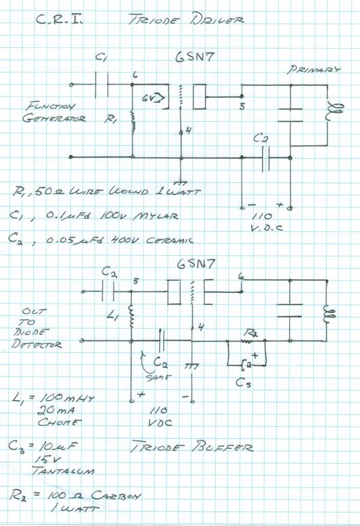
                                I would recommend using a 6SN7 Triode section with cathode drive from function generator and the primary as the plate tank circuit. See the figure. This will greatly improve resonance for tuning. 50 Ohm across primary NFG, 6SN7>6000 Ohm general.

                                Multiple tuning peaks indicate overly tight coupling between coils. Slowly separate them until only one resonant peak. Multiple modes of stray reception and strong local stations will make grounding and tuning very confusing. An isolation amplifier 6SN7 triode isolates amplifier from function generator interaction and gives more power to light neon lamps. Both sections of 6SN7 in parallel give more power.

                                73 DE N6KPH

                                Last edited by t-rex; 05-15-2012, 08:03 PM.
                                SUPPORT ERIC DOLLARD'S WORK AT EPD LABORATORIES, INC.

                                Purchase Eric Dollard's Books & Videos: Eric Dollard Books & Videos
                                Donate by Paypal: Donate to EPD Laboratories

                                Comment

                                Working...
                                X