The Camp David Antenna (1 of 3)
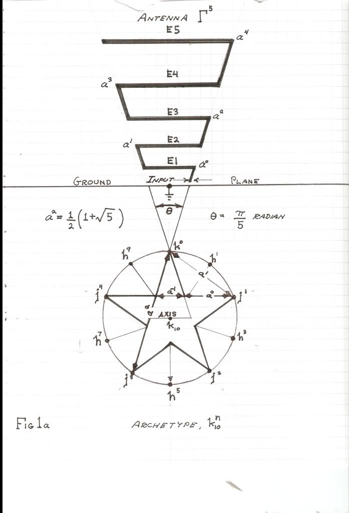
(I) There seems to be considerable confusion regarding the Alexanderson Network as a high frequency antenna for radio communications. I constructed the first version of such a network at the “Camp David” Installation on 450 Overlook, Bolinas, CA. This was done from 1990 to 1994. This installation was obliterated by the County of Marin as a service to the Golden Gate National Recreation Area. Pictures of the Alexanderson network, or array, can be found in the “Barbera Boxer Report” by E.P. Dollard. Camp David, named after its owner David Franklin, was conceived as a civil defense facility for the Town of Bolinas. The Camp David antenna is a dual log-periodic Alexanderson network for high frequency radio communications. Hence forth it will be called the “Bolinas Antenna”. The Bolinas Antenna suited the needs of both Bolinas radio stations KPH and NMC. The “group” did not like this idea so the Bolinas antenna is no more. But the principles are not gone, they exist as mathematical certainties and established engineering formula. The Bolinas antenna is constructed upon two primary engineering considerations: The first is the use of counter-spatial, or reactive, elements, as found in the distributed networks of Tesla and the lumped networks of Alexanderson. The second is the use of a log-periodic sequence of elements as developed thru U.S. Air Force research contracts. The union of these two conditions give rise to a broad bandwidth structure along with “Non Maxwellian” transmission capability. Niether Tesla nor Alexanderson produced such a network, both were very much Single Frequency structures.
The primary objective in the development of the Bolinas Antenna was for telluric transmission and reception in the range of 80 to 40 meters, a one octave band. The Bolinas Antenna consisted of a pair of vertical networks in phase conjunction. The neutral connected directly into the San Andreas Fault line. The log-periodic construction allowed the Bolinas Antenna to also be utilized as an electro-magnetic radiator up to 30 megacycles per second. The compact size and the broadband characteristics make this antenna useful for confined shipboard installations. The theory and design as well as construction details will be developed here.
(II) The counter-spatial, or reactive, transmission network theory is already given in “System for the Transmission and reception of Telluric Electric Waves” by E.P. Dollard. This aspect will therefore not be repeated here. The log-periodic concept will however be developed in the following: Considerable detail on the log-periodic antenna can be found in “The Multi-Wave Oscillator Handbook”, by Tom Brown. A U.S. Psychotronics Assn. Video on the M.W.O. Also exists on “YouTube”. Here can be found the details of my U.H.F. M.W.O. Antenna. Its range was from 300 Mc/sec to 1000 Mc/sec. A “faster than light” speed was expected, but as usual it was time for the “rat to run” so the antenna project vanished to the winds. Be we can rest assured that someone profited from it.
The log-periodic antenna grew out of U.S. AirForce research contracts with the objective of developing a “frequency independent” antenna. The tactical H.F. Radio, and the U.H.F. Spread spectrum systems under development could not operate without such an antenna structure. Unexpectedly here electricity meets with Fibonacci. The log-periodic antennae were found to project themselves into a virtual antenna beyond the physical bounds of their apex. This is analogous to the “plant-archetype” of Rudolf Steiner.
Log-periodic theory states that an electrical structure becomes frequency independent when its constituent sub-structures each exist in a log-periodic sequence. This is to say each elemental network in a series of networks differs from its neighbor networks in a constant logarithmic proportion. Then the concatenated series of networks becomes frequency independent over a finite band, this depending on the total number of individual networks in the log-periodic progression, the more networks the greater the bandwidth.
This log-periodic geometry can be seen in a given rank of organ pipes. The musical scale is a log-periodic sequence in itself. The generalized log-periodic form is derived from the following mathematical expression
 , numeric (1)
Theoretically, there is no beginning, nor is there any end to this sequence, and numerically it must equal infinity. One side continues to become smaller and smaller, while the other side continues to become larger and larger. Naturally, only a finite span of this log-periodic sequence can be utilized in any realizable structure. The pipe organ is a good example of a definite log-periodic span. The largest possible pipe is 32 feet. This is taken as the reference pipe. None can be made larger than this, it is the size of a utility pole. Let for the 32 foot pipe, in the “octave” sequence of a equals two, the total rank be given by;
Beginning,


Thus the entire scale of the pipe organ, in octaves of a equals two, is given as
 , numeric (2)
This mathematical expression serves as a finite span, or scale, out of the infinite log-periodic series of octaves. This scales is symbolized by a log-periodic operator,
 , numeric (3)
Expression (3) is both symbolic and also a definite numeric value,
 (4)
(4)
Hereby, for the pipe organ scale, this operator takes the form,
 (5)
(5)
And
 numeric (6)
This eighth order operator hereby expresses the pipe organ in terms of the log periodic scale of octaves.
The generalized log-periodic series can be reduced to the following expression,
 numeric (7)
Thus it is then derived
 numeric (8)
The root log-periodic operator, and this may be regarded as a kind of “alter-versor”.
During the development of the log-periodic antenna it was discovered that the optimum scaling factor, , was approximately 60 percent, giving a log base of near 1.6. Let a given log-periodic base be given by the relation,
 numeric (9)
This is a vector projection derived from the versor expression,
 unit. (10)
This vector is known as the Golden Ratio. The derived log-periodic is the scaled utilized by Nature in organic formative forces. Numerically it is given as,
 numeric.
(I) There seems to be considerable confusion regarding the Alexanderson Network as a high frequency antenna for radio communications. I constructed the first version of such a network at the “Camp David” Installation on 450 Overlook, Bolinas, CA. This was done from 1990 to 1994. This installation was obliterated by the County of Marin as a service to the Golden Gate National Recreation Area. Pictures of the Alexanderson network, or array, can be found in the “Barbera Boxer Report” by E.P. Dollard. Camp David, named after its owner David Franklin, was conceived as a civil defense facility for the Town of Bolinas. The Camp David antenna is a dual log-periodic Alexanderson network for high frequency radio communications. Hence forth it will be called the “Bolinas Antenna”. The Bolinas Antenna suited the needs of both Bolinas radio stations KPH and NMC. The “group” did not like this idea so the Bolinas antenna is no more. But the principles are not gone, they exist as mathematical certainties and established engineering formula. The Bolinas antenna is constructed upon two primary engineering considerations: The first is the use of counter-spatial, or reactive, elements, as found in the distributed networks of Tesla and the lumped networks of Alexanderson. The second is the use of a log-periodic sequence of elements as developed thru U.S. Air Force research contracts. The union of these two conditions give rise to a broad bandwidth structure along with “Non Maxwellian” transmission capability. Niether Tesla nor Alexanderson produced such a network, both were very much Single Frequency structures.
The primary objective in the development of the Bolinas Antenna was for telluric transmission and reception in the range of 80 to 40 meters, a one octave band. The Bolinas Antenna consisted of a pair of vertical networks in phase conjunction. The neutral connected directly into the San Andreas Fault line. The log-periodic construction allowed the Bolinas Antenna to also be utilized as an electro-magnetic radiator up to 30 megacycles per second. The compact size and the broadband characteristics make this antenna useful for confined shipboard installations. The theory and design as well as construction details will be developed here.
(II) The counter-spatial, or reactive, transmission network theory is already given in “System for the Transmission and reception of Telluric Electric Waves” by E.P. Dollard. This aspect will therefore not be repeated here. The log-periodic concept will however be developed in the following: Considerable detail on the log-periodic antenna can be found in “The Multi-Wave Oscillator Handbook”, by Tom Brown. A U.S. Psychotronics Assn. Video on the M.W.O. Also exists on “YouTube”. Here can be found the details of my U.H.F. M.W.O. Antenna. Its range was from 300 Mc/sec to 1000 Mc/sec. A “faster than light” speed was expected, but as usual it was time for the “rat to run” so the antenna project vanished to the winds. Be we can rest assured that someone profited from it.
The log-periodic antenna grew out of U.S. AirForce research contracts with the objective of developing a “frequency independent” antenna. The tactical H.F. Radio, and the U.H.F. Spread spectrum systems under development could not operate without such an antenna structure. Unexpectedly here electricity meets with Fibonacci. The log-periodic antennae were found to project themselves into a virtual antenna beyond the physical bounds of their apex. This is analogous to the “plant-archetype” of Rudolf Steiner.
Log-periodic theory states that an electrical structure becomes frequency independent when its constituent sub-structures each exist in a log-periodic sequence. This is to say each elemental network in a series of networks differs from its neighbor networks in a constant logarithmic proportion. Then the concatenated series of networks becomes frequency independent over a finite band, this depending on the total number of individual networks in the log-periodic progression, the more networks the greater the bandwidth.
This log-periodic geometry can be seen in a given rank of organ pipes. The musical scale is a log-periodic sequence in itself. The generalized log-periodic form is derived from the following mathematical expression
 , numeric (1)
Theoretically, there is no beginning, nor is there any end to this sequence, and numerically it must equal infinity. One side continues to become smaller and smaller, while the other side continues to become larger and larger. Naturally, only a finite span of this log-periodic sequence can be utilized in any realizable structure. The pipe organ is a good example of a definite log-periodic span. The largest possible pipe is 32 feet. This is taken as the reference pipe. None can be made larger than this, it is the size of a utility pole. Let for the 32 foot pipe, in the “octave” sequence of a equals two, the total rank be given by;
Beginning,


Thus the entire scale of the pipe organ, in octaves of a equals two, is given as
 , numeric (2)
This mathematical expression serves as a finite span, or scale, out of the infinite log-periodic series of octaves. This scales is symbolized by a log-periodic operator,
 , numeric (3)
Expression (3) is both symbolic and also a definite numeric value,
 (4)
(4)Hereby, for the pipe organ scale, this operator takes the form,
 (5)
(5)And
 numeric (6)
This eighth order operator hereby expresses the pipe organ in terms of the log periodic scale of octaves.
The generalized log-periodic series can be reduced to the following expression,
 numeric (7)
Thus it is then derived
 numeric (8)
The root log-periodic operator, and this may be regarded as a kind of “alter-versor”.
During the development of the log-periodic antenna it was discovered that the optimum scaling factor,
 , was approximately 60 percent, giving a log base of near 1.6. Let a given log-periodic base be given by the relation,
 numeric (9)
This is a vector projection derived from the versor expression,
 unit. (10)
This vector is known as the Golden Ratio. The derived log-periodic is the scaled utilized by Nature in organic formative forces. Numerically it is given as,
 numeric.
 , beginning

 numeric (11)
 is the unit size upon which the scale develops. In this case
  (12)
(12)


 (13)
(13)
 length (14)
 length (14)
 percent (15)
 , is
, is length (16)
 = Frequency in C.P.S.


 It's just a convenient thing to use under certain circumstances, like language for communicating with other people. Time travel within these circumstances is physically impossible, because all physical space has changed, that's how come you know it was in the past and now is now, the so-called relative future. If space hadn't changed then it would still be the so-called past, but it would also be "now". It's our idea of time that's incompatible with time travel. That's like playing a game that has certain rules, you can't do certain things as long as you intend to follow those rules. But that doesn't explain anything that happens outside the game. Time travel has no meaning if there is no such thing as time to begin with. If you want to experience the illusion of time travel then simply travel faster through space than the light leaving any particular event on the planet, and then you will have something nice and physical to look at. Now you are experiencing the so-called past. But you are still in the present, it's later than when you set out on your journey, but you're observing something that happened before it. Confusing isn't it, when you have to follow the rules

Comment