Announcement

Collapse
No announcement yet.

Eric P. Dollard

Collapse
This topic is closed.
X
This is a sticky topic.
X
X
 
  • Filter
  • Time
  • Show
Clear All
new posts

  • It looks simple enough on the page.... some complex variables mixed in with some arithmetic. Why does my brain shut down when I see equations like that on the page?

    I guess I will go back to playing in my sandbox with magnets....

    Comment


    • the light

      Originally posted by madhatter View Post
      some more fun with math...
      [((Pi/2) x C)/frequency] = Electrical length, ignoring propagation velocity factor.
      (pi/2) x C = 471,238,898 m/s dielectric velocity
      [471,238,898/f]/4 = (1/4 wavelength of f) meters for extra coil. taking this value and dividing by Pi^2/4 = wavelength of secondary coil in meters.
      nice!

      I know getting to that was not as easy at it looks. Hindsight makes me feel stupid.

      That explains the (pi*C)/(8*f) I ended up with for the extra coil lenght. Then devide by the extra coil multiplier to get the secondary lenght.

      Seeing all the Dollard design equations in long form would be awesome!!

      And this would be the rosetta stone. Wish I had seen the light earlier.

      Comment


      • jibber jabber

        Originally posted by wyndbag View Post
        It looks simple enough on the page.... some complex variables mixed in with some arithmetic. Why does my brain shut down when I see equations like that on the page?

        I guess I will go back to playing in my sandbox with magnets....
        While sand and magnets are fun. Try winding 20 turns of 14 gauge TRT style. It will be more fun then sand. Besides magnets dont work well with sand unless it's black.

        While all the math and theory is exciting and groundbreaking. Its all jibber jabber until someone uses it.

        No offence to all the jibber jabber's. I happen to like all the jibber jabber, both sides are facinating. And without the jibber there will be no jabber. or TRT.

        and yes I watch entirely too much big bang.

        Comment


        • @All Crystal Radio Builders,

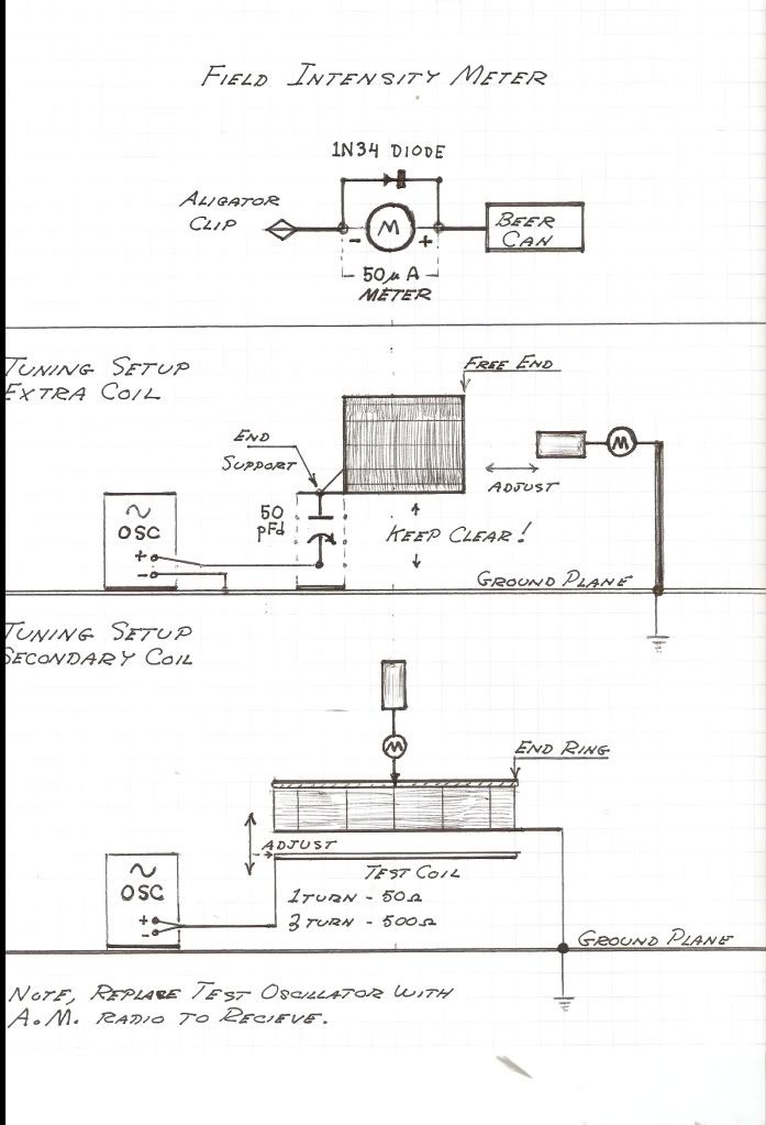
          Eric would like to get some feedback on his given TMT design formulas. The following is a test procedure used to determine the resonance of the coils.


          The best way to get him the data will be to mail the results to the Lone Pine general delivery address.

          Dave

          Comment


          • Originally posted by madhatter View Post
            some more fun with math...
            [((Pi/2) x C)/frequency] = Electrical length, ignoring propagation velocity factor.
            (pi/2) x C = 471,238,898 m/s dielectric velocity
            [471,238,898/f]/4 = (1/4 wavelength of f) meters for extra coil. taking this value and dividing by Pi^2/4 = wavelength of secondary coil in meters.
            Exactly. And with this you can design the length and diameter for your coils for any desired frequency f, as I posted before:

            Originally posted by lamare View Post
            Why this h/d = 1?

            Let's consider the extra coil to be a wave guide that conducts only in one direction, along the coil windings. The normal, transverse wave travels in circles around the coil. Since we want to suppress that one, the circumference should be n * 1/2 lambda transverse, with n = 1,3,5,....

            So, we should choose our diameter D = (n * 1/2 lambda transverse) / pi.

            The longitudinal waves travels along the length of the coil. Now the wavelength of the longitudinal wave for the same frequency is pi/2 times as long. So, for D calculated as above, we get a longitudinal wavelength along the length direction of the coil of pi/2 times ((n * 1/2 lambda transverse) / pi) = n * 1/4 lambda transverse.


            So, for a give diameter D, when we have a n * 1/2 lambda transverse along the circumference, we have a corresponding n * 1/4 longitudinal wavelength across the length of the coil that equals D.

            So, now you can design your extra coil for a certain frequency...

            So, the extra coil does not HAVE to be h/d = 1. Only in the case you want a 1/4 lambda waveguide / coil, you take h/d = 1. If you want a 3/4 lambda, you take h/d = 3.

            And you can also play with n, BTW.

            What is most important is to calculate the diameter such that you suppress the transverse wave at the desired operation frequency.
            Since you do not want to suppress the transverse wave in the primary, this one should have twice the diameter of the extra coil, since then there is a full wavelength for the transverse wave around your primary. That way you have matched the transverse EM resonance in your primary to the longitudinal resonance in your extra coil.

            Now the secondary should be a pancake coil in Tesla's design. It appears that functions as a transformer from the current/magnetic dominated form of energy in the primary into the voltage/dielectric dominated form of energy in the extra coil.

            I found an interesting paper some time ago about the propagation factor of waves, which suggests that the propagation speed of EM signals around coils depends mostly on the h/d ratio:

            http://www.tuks.nl/pdf/Reference_Mat...ity_Factor.pdf

            A very interesting detail with regards to flat coils, is that this propagation factor appears to go to 0 for flat (h/d < 0.5 or so) coils, such as pancake coils. That suggests that the geometry of a flat or pancake coil makes that EM signals can hardly propagate trough it.

            For the pancake spiral coil, this suggests that the capacitive coupling between the coil windings gradually becomes the dominating coupling mechanism going from the outside to the inside of the coil and that it thus transforms the energy from EM to longitudinal dielectric.
            Last edited by lamare; 04-09-2012, 04:44 PM. Reason: some rephrasing

            Comment


            • Easy Breezy

              Originally posted by lamare View Post
              Exactly. And with this you can design the length and diameter for your coils for any desired frequency f, as I posted before:


              Since you do not want to suppress the transverse wave in the primary, this one should have twice the diameter of the extra coil, since then there is a full wavelength for the transverse wave around your primary. That way you have matched the transverse EM resonance in your primary to the longitudinal resonance in your extra coil.

              Now the secondary should be a pancake coil in Tesla's design. It appears that functions as a transformer from the current/magnetic dominated form of energy in the primary into the voltage/dielectric dominated form of energy in the extra coil.

              I found an interesting paper some time ago about the propagation factor of waves, which suggests that the propagation speed of EM signals around coils depends mostly on the h/d ratio:

              http://www.tuks.nl/pdf/Reference_Mat...ity_Factor.pdf

              A very interesting detail with regards to flat coils, is that this propagation factor appears to go to 0 for flat (h/d < 0.5 or so) coils, such as pancake coils. That suggests that the geometry of a flat or pancake coil makes that EM signals can hardly propagate trough it.

              For the pancake spiral coil, this suggests that the capacitive coupling between the coil windings gradually becomes the dominating coupling mechanism going from the outside to the inside of the coil and that it thus transforms the energy from EM to longitudinal dielectric.

              Sounds great. But it makes not sense to me. Because there are no waves, no wavelenghts, in my theory of TRT opperation.

              BUT you may be right.

              Give me some design equations like the ones Dollard posted that will allow me to build a receiver that can light a #327 bulb. 1620AM or just based on Frequency like Dollards. I have 30meters of flat copper 0.25' wide foil that I have been wanting to make a pancake coil with.

              If I can I will build it. I will let you know what happens. I think I have everything except the the design equations.


              jake

              Comment


              • Originally posted by jake View Post
                Sounds great. But it makes not sense to me. Because there are no waves, no wavelenghts, in my theory of TRT opperation.

                BUT you may be right.

                Give me some design equations like the ones Dollard posted that will allow me to build a receiver that can light a #327 bulb. 1620AM or just based on Frequency like Dollards. I have 30meters of flat copper 0.25' wide foil that I have been wanting to make a pancake coil with.

                If I can I will build it. I will let you know what happens. I think I have everything except the the design equations.


                jake

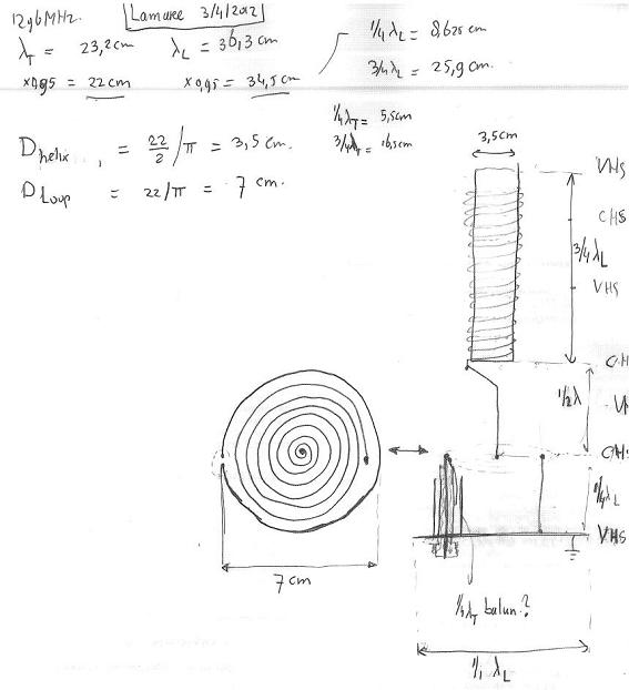
                I posted a sketch of what I am thinking of building for 1296 MHz at the moon bounce thread:

                http://www.energeticforum.com/renewa...tml#post186991


                The principal design parameters in that design are the longitudinal and transverse wavelengths.

                For 1296 MHz, the transverse wavelength is roughly 300/1296 = 23 cm. The longitudinal is 1.57 times that = 36 cm.

                For 1620 Khz, or 1.62 MHz, you are talking about 185 meters for the transverse and 291 meter for the longitudinal!!

                So, for 1620 KHz you would be talking about an extra coil with a length of over 70 meters.

                Now obviously, you can operate Tesla coils at much lower frequencies than with the theoretically optimal dimensions, obtained by considering the extra coil as a waveguide and the primary as a circular feed.

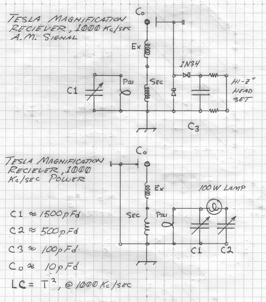
                In that case, you need to add additional capacitors to tune the system and get it to resonate at lower frequencies than the natural resonance frequencies of your coils, as Eric posted:
                http://www.energeticforum.com/renewa...tml#post173955


                In that case, it is much more difficult to predict what happens exactly around your (extra) coil, because you do not have the situation that transverse waves propagating around your extra coil windings in spirals naturally cancel one another out on one single winding. At this moment, I really can't say anything sensible on that situation.

                So, if you want to do without tuning capacitors and still have practical physical dimensions, you would run the system at least at 100 MHz or so.

                And remember, with Eric/Tesla's TMT system, your energy flows trough the ground (connection), while with the design I intend to build, I intend to use the extra coil as a real transmitter antenna, whereby a ground plane is added in order to reflect any waves that would otherwise radiate away to the ground direction.
                Last edited by lamare; 04-09-2012, 07:03 PM.

                Comment


                • Originally posted by lamare View Post
                  I posted a sketch of what I am thinking of building for 1296 MHz at the moon bounce thread:

                  http://www.energeticforum.com/renewa...tml#post186991


                  The principal design parameters in that design are the longitudinal and transverse wavelengths.

                  For 1296 MHz, the transverse wavelength is roughly 300/1296 = 23 cm. The longitudinal is 1.57 times that = 36 cm.

                  For 1620 Khz, or 1.62 MHz, you are talking about 185 meters for the transverse and 291 meter for the longitudinal!!

                  So, for 1620 KHz you would be talking about an extra coil with a length of over 70 meters.

                  Now obviously, you can operate Tesla coils at much lower frequencies than with the theoretically optimal dimensions, obtained by considering the extra coil as a waveguide and the primary as a circular feed.

                  In that case, you need to add additional capacitors to tune the system and get it to resonate at lower frequencies than the natural resonance frequencies of your coils, as Eric posted:
                  http://www.energeticforum.com/renewa...tml#post173955


                  In that case, it is much more difficult to predict what happens exactly, because you do not have the situation that transverse waves propagating around your extra coil windings in spirals naturally cancel one another out on one single winding. At this moment, I really can't say anything sensible on that situation.

                  So, if you want to do without tuning capacitors and still have practical physical dimensions, you would run the system at least at 100 MHz or so.
                  Acutally a little over 70 meters is correct. That is not out of the realm of practical. Its very possible and it can been done relatively easy.

                  As far as the "185 meters for the transverse and 291 meter for the longitudinal!!" How would these influance your design? I know where the 185came from but where did the 291 come from what do these have to do with the size of the coils in your design? Im not into transmitting, but according to Tesla the receiver is just a mirror of the transmitter.

                  Using only your understanding of RF, do you think it is possible to light a #327 bulb with a tuned antenna circuit tuned to an AM radio station 10kW 5mi away(actually more then 5mi but lets be conservitave)? Or would you say what I am trying to do is impossible, not gonna happen?

                  Jake

                  Comment


                  • Originally posted by jake View Post
                    Acutally a little over 70 meters is correct. That is not out of the realm of practical. Its very possible and it can been done relatively easy.
                    You do realize you are talking about a coil with a height AND diameter of 70 meters, right?

                    As far as the "185 meters for the transverse and 291 meter for the longitudinal!!" How would these influance your design? I know where the 185came from but where did the 291 come from what do these have to do with the size of the coils in your design?
                    291 = pi/2 (1,57) times 185, because the longitudinal waves are assumed to propagate at a speed of pi/2 times c. However, this may also turn out to be sqrt(3), since according to Stowe that is the theoretical speed difference between longitudinal and *real* transverse waves in an elastic medium:

                    Tuks DrippingPedia : Stowe Foundation Unification Physics
                    In classic kinetic theory, longitudinal (simple compression) wave speed is defined as:

                    c_l = sqrt(3q / rho) {eq. 4a}

                    where rho is the density of the medium and q is systemic pressure.

                    Transverse waves in an elastic medium are defined as:

                    c_t = sqrt(q / rho) {eq. 4b}
                    However, EM waves in the far field are NOT real transverse waves. So, it may very well turn out that transverse EM waves propagate with a speed of sqrt(3)/ (pi/2) = 1.1 times the speed of light in the near field, and with the speed of light in the far field.

                    Anyway, I posted some on the h/d stuff a few days ago:
                    http://www.energeticforum.com/renewa...tml#post186877

                    But it appears, I made a thinking error.

                    When you take the diameter of your coil such that it's circumference is a half wavelength of your normal, transverse wave, then you have a radius of lambda_t/2 / pi, or a diameter of lambda_t / pi. And since the normal transverse wave propagates by means of inductance (see The L.M.D./T.E.M.Test and Eric's corresponding experiment), that is the one spiraling around your coil and is thus in anti-resonance when you have a diameter of lambda_t / pi.

                    When you calculate with a propagation speed difference of pi/2, then the corresponding longitudinal wavelength is pi/2 as long. Since that one propagates by means of the capacitive coupling between your coil wires, that one would propagate along the length of your coil, so you would take a height of a quarter longitudinal wavelength, or 1/4 * lambda_l = 1/4 * pi/2 * lambda_t.

                    Then the h/d ratio = (1/4 * pi/2 * lambda_t ) / (lambda_t / pi)
                    = 1/4 * pi/2 * lambda_t * pi/lambda_t
                    = 1/4 * pi/2 * pi = pi^2 / 8 = 1.23

                    So, we get a h/d ratio that is pretty close to 1, but the height of the coil should be about 23% more than it's diameter according to this theoretic exercise.

                    When you calculate with sqrt(3) (for the near field), you would get:
                    h/d ratio = (1/4 * sqrt(3) * lambda_t ) / (lambda_t / pi)
                    = 1/4 * sqrt(3) * pi= 1.36.

                    Once again, these calculations assume no capacitance to be present at the top of the extra coil.

                    Im not into transmitting, but according to Tesla the receiver is just a mirror of the transmitter.
                    Yes, the receiver is a mirror of the transmitter. You can always use an antenna system just as well to transmit or to receive. And actually, a receiving antenna/coil in resonance also acts as a (re)transmitter, along good old Huygens principle:

                    Huygens–Fresnel principle - Wikipedia, the free encyclopedia
                    Huygens proposed that every point to which a luminous disturbance reaches, becomes a source of a spherical wave and the sum of these secondary waves determines the form of the wave at any subsequent time.


                    Using only your understanding of RF, do you think it is possible to light a #327 bulb with a tuned antenna circuit tuned to an AM radio station 10kW 5mi away(actually more then 5mi but lets be conservitave)? Or would you say what I am trying to do is impossible, not gonna happen?

                    Jake

                    According to normal RF theory, the power density should rapidly decrease along the inverse-square law, at least in free space:

                    Radio propagation - Wikipedia, the free encyclopedia
                    In free space, all electromagnetic waves (radio, light, X-rays, etc.) obey the inverse-square law which states that the power density of an electromagnetic wave is proportional to the inverse of the square of the distance from a point source.
                    When you are talking 5 miles, that would be about 8000 meters. Then the power density at the receiver should be about 10.000/8000^2 = 0.16 mW.

                    So, according to normal propagation theory, lighting a light bulb by means of RF waves transmitted trough the air should be impossible.

                    BUT, the transmitter not only transmits directly trough the air. Part of the transmitted power is transmitted in the direction of the earth. And according to Tesla, the earth is capable of resonating at multiples of it's natural resonance frequency of something like 10 Hz or so. That means, that it could very well be possible that a part of the transmitted power is not radiated away into space, but is actually "captured" as a standing wave propagating trough the interior of the the Earth.

                    And if that is correct, you could pick up the energy of that standing wave at any point upon the surface of the Earth by means of a good ground connection and a resonating receiver apparatus. Now suppose only 1% of the transmitted energy of a 10 kW transmitter is not reflected by the Earth surface, but ends up in a standing wave trough the interior of the Earth, then that standing wave would have a total power of about 100 W. Now if you are the only one tapping into that resonating standing wave, then you should be able to just about light a 100W light bulb....

                    However, this of course is very speculative.

                    Comment


                    • Not far from my home is what is referred to locally as the Hornet Spook Light". It kind of acts like Ball lightning, in that it moves around. Sometimes very tiny lights seem to emanate from the ground. Perhaps this light is the result of some sort of by product of longitudinal geo resonance. Lots people with way more knowledge of science than me have tried to explain this one.
                      No one so far has a clue. Using Tesla theory, what sort of measurements would a scientist make?

                      Comment


                      • Originally posted by lamare View Post
                        In that case, it is much more difficult to predict what happens exactly around your (extra) coil, because you do not have the situation that transverse waves propagating around your extra coil windings in spirals naturally cancel one another out on one single winding. At this moment, I really can't say anything sensible on that situation.

                        So, if you want to do without tuning capacitors and still have practical physical dimensions, you would run the system at least at 100 MHz or so.

                        And remember, with Eric/Tesla's TMT system, your energy flows trough the ground (connection), while with the design I intend to build, I intend to use the extra coil as a real transmitter antenna, whereby a ground plane is added in order to reflect any waves that would otherwise radiate away to the ground direction.
                        Ok so how does this equate as far as longitudinal waves go, to Tesla's
                        Colorado Springs transformer with a secondary 15 meters diameter and the
                        extra coil at about 2 meters diameter when he was using frequencies around 30 to
                        50 Khz or so ? The 1/4 wavelength at 36 Khz is over 2000 meters.

                        The way I see it if the longitudinal component takes a shorter path then the
                        speed of propagation should be calculated using the shorter path not the
                        length of the wire or the "EM electrical length". Shouldn't it ?

                        Cheers

                        Comment


                        • Lamare, I've been working with this field solver (fast henery2) and thought it might provide some headway on design.
                          here's a bit about the program.

                          "The results are provided in form of a Maxwell impedance matrix Z=R+jL, where the bold letters represent matrices. Then, the results can be converted in equivalent, SPICE-like, lumped elements circuit models with an utility provided with FastHenry2, MakeLCircuit. The network thus obtained, however, is valid only for a single frequency. Alternatively, is possible to generate directly with FastHenry2 a SPICE-like circuit capable to model frequency-dependant inductances and resistances. This latter opportunity is very powerful because allows to see how signals in the time domain are degradated by the different response of the conductors at the various frequencies.
                          The classic approach, from which FastHenry2 differs, is the following: once the frequency response is calculated in the frequency domain, then a FFT or a Laplace transform is used to obtain a behavioral description in the time domain. Next, a convolution (or similar technique) is applied to get the temporal response of the circuit. The conversion from the frequency domain to the time domain is necessary, as the characterization of the lines in the frequency domain is in term of irrational functions of the frequency variable. Therefore, a generic SPICE-like simulator, being based on the numerical integration of ordinary differential equations, deriving from a lumped elements circuit whose parameters are characterized by rational functions in the frequency domain, in not capable to handle elements characterized by irrational functions. The advantage of FastHenry2 is achieved by the fact that it is possible to find rational approximations of these functions, at least in a fixed range of frequencies, and so operate only in the time domain. Following this approach, FastHenry2 is capable to generate Reduced Order Models (ROM) for the system, which are valid, according to the selected expansion order, up to a defined maximum frequency. "

                          i've been able to generate a layout for the secondary and extra coil, not the primary at the moment. what's needed is a C+ script to compile a spiral into X,Y,Z coordinate points for the field solve to generate the surfaces to work with. I have a script for a helix but so far the spiral is being difficult.

                          on waves and fields, I look at it like the Heisenberg Bohr model, not an actual physical thing but a probability with uncertainty. Of course Einstein objected to this at the 1927 Solvay Conference, Einsteins view that the wave collapses where the effect is measured is radical in the least, yet that is the current view. How this doesn't violate the velocity if C is even more amusing. what's the point? If the wave is viewed as a probability of where the peaks and valleys are to be found, then velocity is only a function of the time domain and the photon is not the limit as the photon velocity is a function of it's probability field. I'm trying to keep the description simple as I'm not going into wave groups, trains and measurement variations.

                          It may on the outset seem unrelated however since it seems we are looking for the fundamental effect of the dielectric in order to create a longitudinal wave we are faced with the 'quantum' realm. But this diverts into a much deeper subject that is not the point of this thread, but it does touch on it.

                          Comment


                          • @ lamare,

                            Thanks

                            I did not realize it was 70m diameter. I was thinking conductor length. But that was pretty obvious.

                            Thanks again for your lesson. It will help me in the future. More questions coming soon.

                            Jake

                            Comment


                            • lamare, you may find this article useful. I hope I'm not late to the party with this article, it's a couple yrs old.
                              http://www.nature.com/nphoton/journa....2008.127.html


                              what's interesting to note, longitudinal wave in free space.

                              Comment


                              • The Camp David Antenna (2) (1 of 2)

                                (I) In the prior section a golden ratio log-periodic array was developed. This array can operate in two modes, a spatial mode and a counter-spatial mode. In the spatial mode the array is an electro-magnetic antenna. This mode is operative when the applied frequency is within the range of its log-periodic span. In the counter-spatial mode the array is a reactive network operating at the fundamental frequency as determined by the total wire length Lo. This mode is known as a quarter wave resonant line. Little information exists with regard to this mode of operation. Marconi utilized such arrangements to circumvent the Tesla Transformer patents. See “Vril Compendium, Aerial Radio”, by Vassilatos. Here they are called “articulated antenna.” In both the spatial and counter-spatial modes of operation this log-periodic structure is of an un-balanced, or asymmetrical form. Hence it must operate over an infinite ground plane.

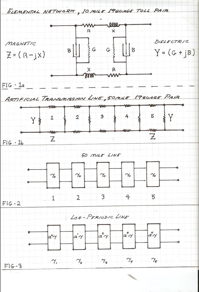
                                (II) The log-periodic theory can be applied to networks as well as antenna. Consider a concatenated sequence of reactive networks in a most basic form. This is the artificial transmission line as conceived by A. Kennelly, Fig (1). Each individual network, , in the sequence is identical to the one that follows it and the one that precedes it, Fig (2). In this example the scale factor a is unity. For a log-periodic concatenated sequence of networks each individual network differs from that which follows it and that which precedes it, this by a constant numeric ratio, Fig (3). This constant is the Scale Factor, a,

                                numeric (1)


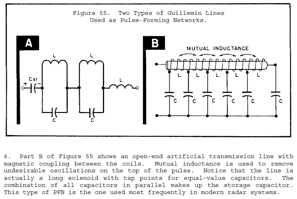
                                Both structures can be regarded as artificial lines, but in the case of the log-periodic line, its parameters depart further from those at the input as the progression down the length of the line increases. This is to say the output bears no resemblance to the input but is transformed by the compounded scale factor, , where N is the total number of networks in the log-periodic sequence. Thus the log-periodic line is not a transmission structure in the normal application. This suggests that rather than a transmission structure the log-periodic line is more like what is known in network theory as a Reactance Arm. See “Communication Networks” by Ernst Guillemin. Also see information on the “Guillemin Line” for radar use.
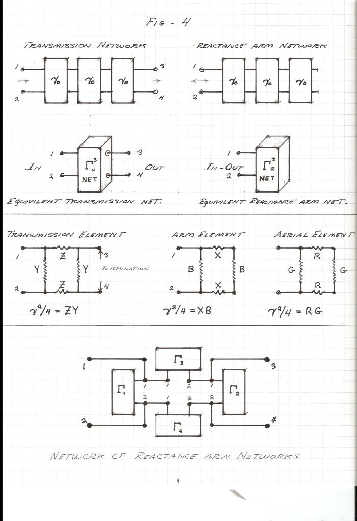
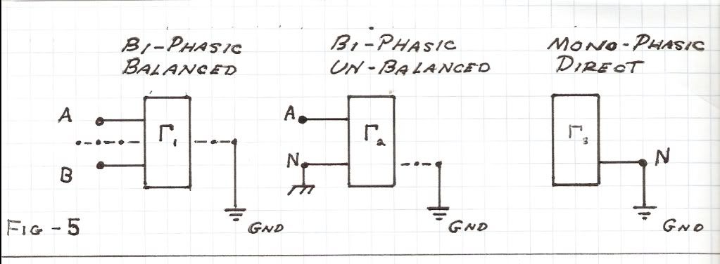
                                In a normal transmission structure there exists a set of input terminals and a set of output terminals, each distinct from the other. The exact number of terminals depends on the number of phases, two being common, Fig (4). For the reactance arm there is only one set of terminals which serve as both input and output. Considering this in terms of the common antenna it also has only one set of terminals, the input on transmit, or the output on receive. The other set of terminals is into, or out of, the Aether, this in accord with the Law of Reciprocity. This set of terminals can take on three distinct forms, Fig (5),

                                1)Bi-Phasic Balanced,

                                2) Bi-Phasic Un-Balanced,

                                3) Mono-Phasic, Direct.


                                Condition one is the common dipole antenna fed by a balanced two wire line,

                                Condition two is the A.M. Broadcast tower fed by a co-axial line,

                                Condition three is the Tesla Transformer directly Earthed.

                                Condition two is a special case of condition one and is a half antenna. The conjugate half antenna is the reflection of it by the ground plane. This is a mirror (phase opposition) image and is known as the “image antenna”. No such image exists for condition three. This is an area of the unknown but will be the beginning point for the “Bolinas Antenna”.

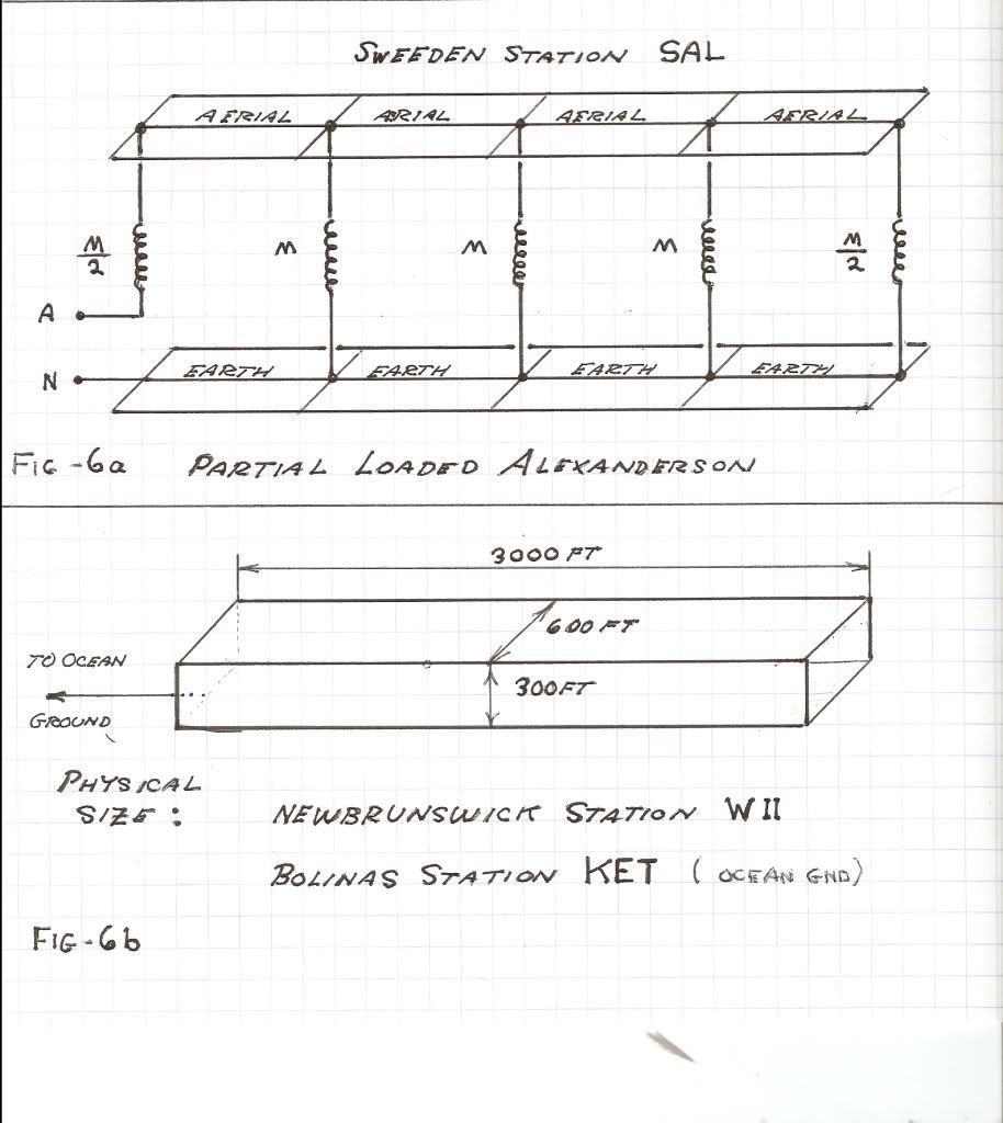
                                (III) Our objective is to apply the log-periodic principle to the Alexanderson multiple loaded flat top aerial structure. Ernst Alexanderson developed several antenna structures for General Electric and Radio Corporation efforts at the Bolinas Marconi-R.C.A. Station, 1920. One in particular became very well known as the Alexanderson V.L.F. Multiple loaded array. Bolinas was to have the full embodiment of the Alexanderson patents, whereas later stations were only to be partial versions as shown in Fig (6). A complete working station still stands in Sweden, call sign SAL. In Bolinas only concrete foundations remain. Fortunately the efforts of the G.G.N.R.A. axis to destroy these failed. Here is where I began my “re-awakened” study of the Alexanderson system after reading the “Vril Compendium” by Vassilatos (1998). This led to the highly developed “Landers Antenna”.


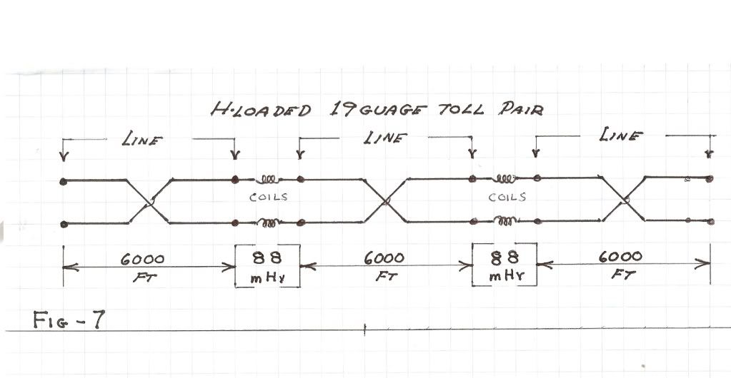
                                (IV) The basic Alexanderson concept can be regarded as an extension of the loaded telephone line, the path is from Heaviside to Pupin, then Campbell. This became the “Bell System”, the “8th Wonder of the World”, (not anymore). Telephone loading made the frequency response of wire lines much more uniform by correcting for the distortion introduced by the conductivity of the wires. This distortion became severe in cable circuits. The loaded telephone line is a sequential series of reactance coils and of twisted pair wire lines, Fig (7). For “Code H” toll circuit loading the complete line is made up of 19 gauge twisted pairs in spans of 6000ft length, each span is interconnected to the adjacent spans thru an 88 milli-henry set of reactance coils.


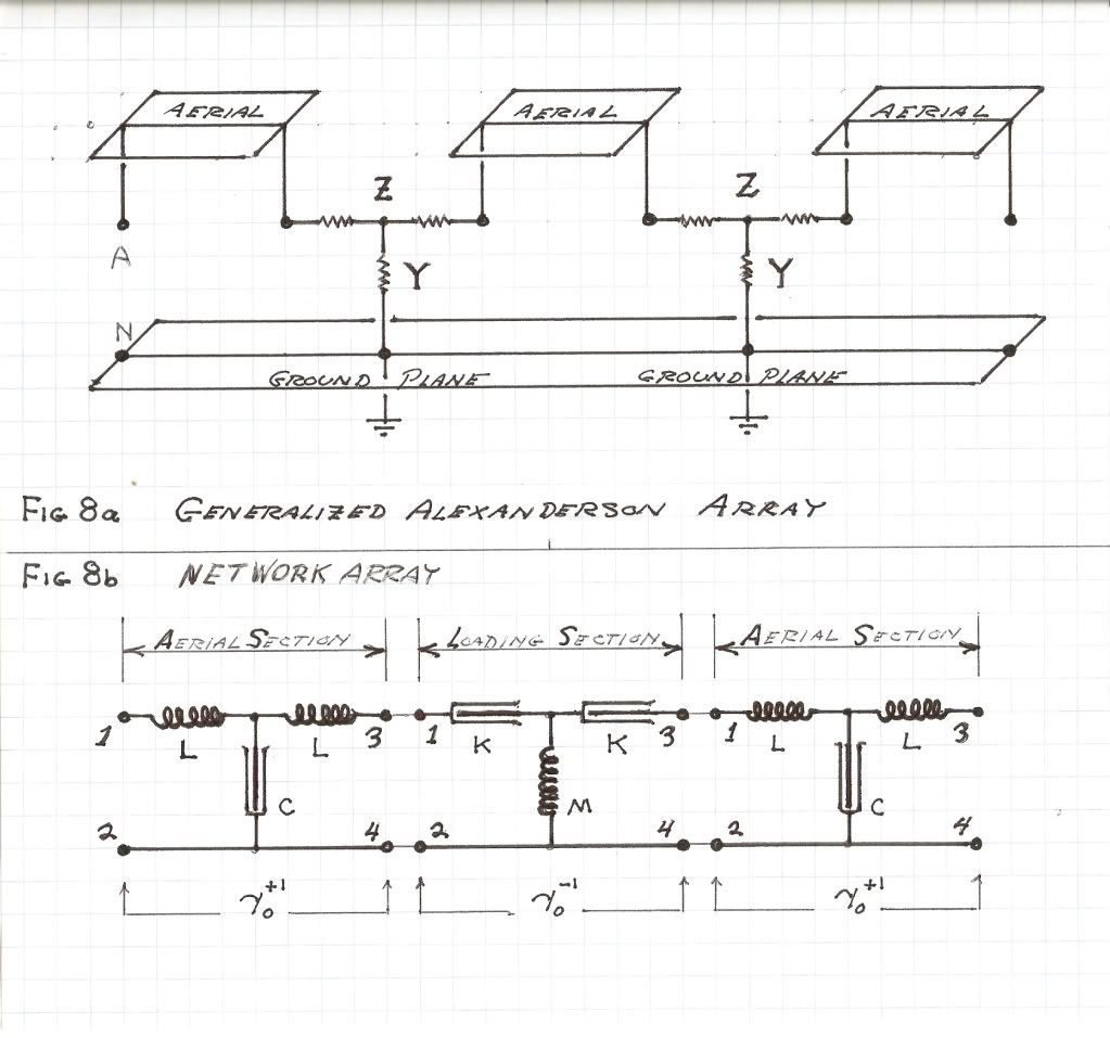
                                The generalized Alexanderson multiple loaded array is shown in Fig (8). Reactance arms Z and Suceptance arms Y can be of any form and here are symbolized as simple resistors for simplicity. It can be seen that the Alexanderson loading is in many ways the same as the telephone line loading. It is however the loaded cable pair is a terminated transmission line, whereas the “Alexanderson Line” is open ended, or a stub line, and thus in itself is a reactance arm with only one set of terminals. Further it is that the twisted pair has no external electric field, whereas the objective in the Alexanderson Line is a totally external electric field. This is a dielectric field carrying a displacement current. The AETHER is the output of the Alexanderson Line, whereas a TELEHONE is the output of the loaded pair. The Alexanderson system is operated in the geo-physical critical frequency band around 20 kilocycles per second, (this is in the V.L.F. Range, 3kc to 30kc). This band is a convergence between Telluric Frequencies and Atmospheric Frequencies, and it shifts days before large seismic events. See “Vril Compendium”, “Military V.L.F. Radio”, by Vassilatos. This is an important area of research. (Landers)

                                (V) It is little known that Ernst Alexanderson also developed high frequency, (3 megacycles to 30 megacycles), electro-magnetic antennae for the Bolinas station. Two in particular are noteworthy,

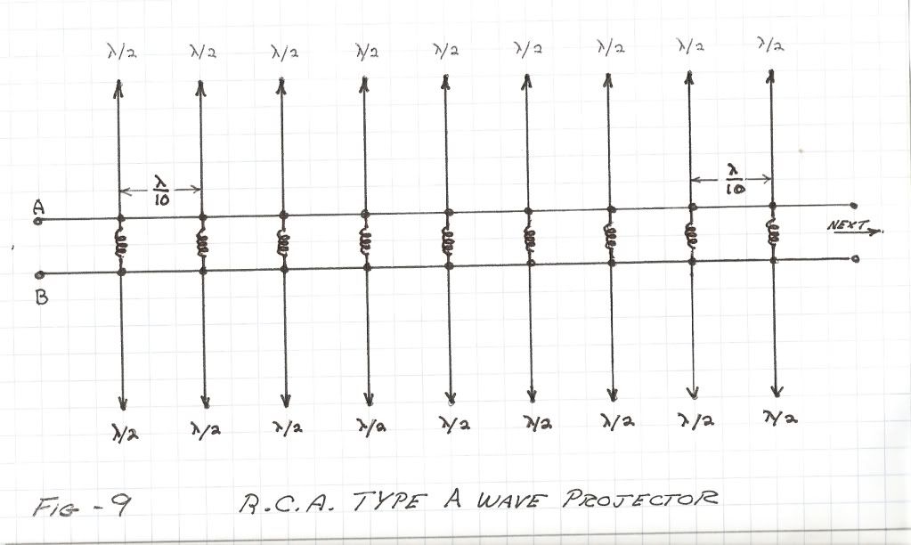
                                1) The R.C.A. type A wave projector, Fig (9)

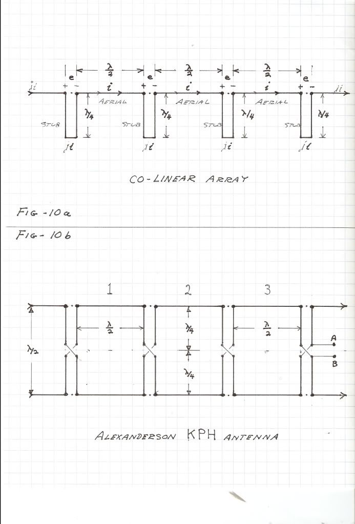
                                2) The Collinear Dipole Array, Fig (10)


                                Both antennae utilize the Alexanderson loading scheme. The type A is loaded transmission line structure and led to the R.C.A. “Fish Bone” antenna later developed by Beverage, Carter, and Hansel of R.C.A. Laboratories. For more on these R.C.A. developments see “Radio Antenna Engineering” by Laport, here are numerous photos and diagrams of the “Lost Antennae” of Bolinas.

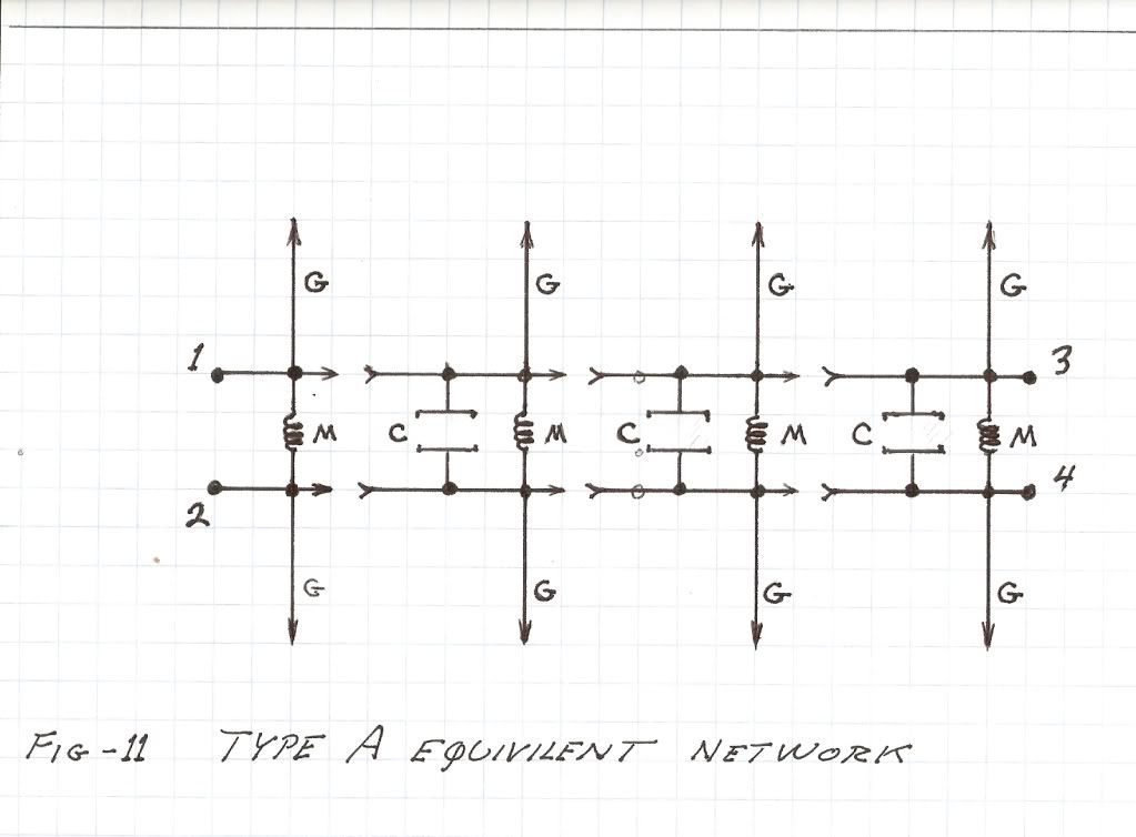
                                In the type A each loading section on the two wire line is a parallel connection of an electro-magnetic dipole and a shunt reactance coil. This coil is so proportioned to cancel the dielectric induction of the span of two wire line preceding it, Fig (11).


                                This shunt reactance “tunes out” the shunt capacitance of the line element, and thereby tunes out the Velocity of Light, the actual dimensions of the capacitance. The result is no time delay along the two wire line exciting the radiators. Propagation is now instantaneous. Hereby all the radiators operate in phase unison resulting in the type A being a broadside array with a vertical polarization. Since no standing waves are possible on a line with no propagation delay all radiators appear in parallel at the feed terminals. A 600 ohm resistive impedance results. The Type A is obviously a single frequency antenna and this is its prime defect. R.C.A. operated the A arrays at power levels of 40 to 80 kilowatts at frequencies in the H.F. point to point service.
                                SUPPORT ERIC DOLLARD'S WORK AT EPD LABORATORIES, INC.

                                Purchase Eric Dollard's Books & Videos: Eric Dollard Books & Videos
                                Donate by Paypal: Donate to EPD Laboratories

                                Comment

                                Working...
                                X