Announcement

Collapse
No announcement yet.

Eric P. Dollard

Collapse
This topic is closed.
X
This is a sticky topic.
X
X
 
  • Filter
  • Time
  • Show
Clear All
new posts

  • Now I've got to really think about this last bit, I put together another core, two magnet disks 3" dia, 2 copper disks 2.75" dia all with .25" hole, sandwiched the copper disks with a piece of .125" thick neoprene. 20 turns of 26ga mag wire.

    putting a static 9vDC charge on the plates has a very interesting effect on the windings, now the charge is via a wall unit so it's not battery clean. the meter reads 2v AC on the leads if there is a small .001uF capacitor in series. now if I touch the magnets the voltage fluctuates due to my body capacitance. another interesting feature, take the ground lead of the meter and attach to a clean ground, I have a rod for this. leave the positive lead on one of the winding ends, it'll will read ~10vAC, If I touch the magnets the voltage jumps to ~23vAC and climbs to 43VAC.

    if I remove the ground lead from the ground and touch it with my finger it'll read ~7VAC.

    putting in a diode it'll read .5vDC on the windings.

    THis is all with a static 9Vdc charge on the plates in the magnet core transformer.

    need to source some highly permeable material to make layered cores with copper plates and see what I get without the impressed magnetic field already in place.

    Comment


    • Originally posted by madhatter View Post
      OK interesting, lets work this out.
      a quick and dirty core was made of 4 large flat washers, 3.5" dia with a 1" hole in the center, layered with poly plastic. 22ga mag wire wound 4 turns in traditional manner. 2nF capacitance on the core.

      applied an .5v 1kHz sine wave to the 'capacitor plate' core and picked up a AC signal on the windings, applied same .5v sine wave to windings and picked up the AC signal on the core. nothing in this setup is optimized it was simply to see if the magnetic field would induce voltage in the windings and vice versa, it does.

      So now the question is how?, esp the capacitor arrangement.

      going to build a another core with the capacitor plates arr
      anged vertical and see what that does to the magnetic field.

      the sine wave was feeble in getting a response, a square wave would be best, however the signal generator I have doesn't output square, need to build a full bridge circuit and re-test.
      Going old school. I like it.

      Also don't call that static dc until you put a scope on it. A lot of those don't even have a smoothing cap. Make your own smoothing cap.

      Comment


      • "Flux Capacitor"

        Madhatter,

        It would seem this little experiment has some potential. If possible could you post a picture of your setup, I am going to give it a go tomorrow when I get some more free time.

        I had an interesting thought, what if you hooked up an Arial to one side of the "capacitor" and an earth ground to the other. I am curious if you could tap the free flowing electrostatic displacement currents between the earth and clouds and translate it to low voltage high current ac on the coil side of things.

        Thanks for posting your experiment, its got me thinking of some crazy "free energy" devices.

        Garrett M

        Comment


        • Originally posted by jake View Post
          Going old school. I like it.

          Also don't call that static dc until you put a scope on it. A lot of those don't even have a smoothing cap. Make your own smoothing cap.
          Oh I know it's not clean, whats interesting is the windings do indeed pick up the 60Hz cycle. I did use a smoothing cap expecting a change, nope all that happens is the 60Hz hum goes away. putting a diode bridge on one lead of the winding terminal is very sensitive to capacitance.

          I need to play with this some more, as this is a very fascinating discovery.

          Comment


          • Originally posted by garrettm4 View Post
            Madhatter,

            It would seem this little experiment has some potential. If possible could you post a picture of your setup, I am going to give it a go tomorrow when I get some more free time.

            I had an interesting thought, what if you hooked up an Arial to one side of the "capacitor" and an earth ground to the other. I am curious if you could tap the free flowing electrostatic displacement currents between the earth and clouds and translate it to low voltage high current ac on the coil side of things.

            Thanks for posting your experiment, its got me thinking of some crazy "free energy" devices.

            Garrett M
            This is indeed a very, very strange experiment and results. I'm still trying to figure how the windings are picking up an AC voltage of such high potential when the plates are charged, I figured the effect would be more pronounced with pulsed dc.

            I did try a few things, leave on plate wire free and feed the other with the positive feed of the dc transformer. take the winding leads, one is attached to a capacitive foil sheet the other is fed to the meter, the ground lead of the meter is clamped to a clean ground rod. AC voltage is roughly equal to the DC voltage of the transformer.

            there is many different things to try here, and I fiddled around with a number of things.

            I want to try a few different designs, let me put some diagrams together and I'll post 'em for you to try as well.

            Comment


            • here's where I started, the windings are shown as air wound here however in reality I wound them against the core.


              Uploaded with ImageShack.us

              Comment


              • Mutual Inductance, 1/4 Wavelength and how it Relates to Standing Waves and Longitudinal Propagation - A Visual Dimensional Analysis

                Warning: This is my personal Theory and Wild-Conjecture.

                Firstly let me quote O'Neill from The Prodigal Genius pg.119

                "Tesla did not invent the idea of electrical resonance. It was inherent in the mathematical description of the condenser discharge as developed by Lord Kelvin, and in the physical nature of alternating currents; but Tesla changed it from a buried mathematical equation to sparking physical reality. It is the analogy of acoustical resonance which is a natural property of matter.

                However, there were no practical circuits in which resonance could manifest itself until Tesla developed alternating currents, particularly the high-frequency currents. He put the master's touch to the research in this field by developing the principle of resonance in individual circuits through adjustment of capacity and inductance; the amplification of effects by inductive coupling of two tuned circuits, and the peculiar manifestations of resonance in a circuit tuned to a quarter of the wavelength of the energizing current.

                This latter development was a stroke of pure genius. In the vibrating string, two loops measure a complete wavelength and one loop measures half a wavelength, since one of the loops is up when the other is down. Between the two loops is a nodal point which does not move. From the nodal point to the top of a loop is a quarter wavelength.Taking the quarter wavelength as a unit, one end is motionless and the other end swings through the greatest amplitude of vibration. By tuning his coils to quarter wavelengths, one end of the coil, Tesla found, would be entirely inactive while the other end would swing through tremendous electrical activity.

                Here was a unique situation, one end of a small coil inert and the other end spouting a flood of sparks of hundreds of thousands or even millions of volts. In a physical analogy it seemed like the Niagara River reaching the edge of the precipice--and then its waters shooting mountain high in a gigantic fountain instead of fallinginto the chasm. The quarter-wavelength coil is the electrical counterpart of the vibrating tine of the tuning fork, the ordinary clock pendulum, or the vibrating reed. Once accomplished,it was a simple thing--but its discovery was a work of genius."

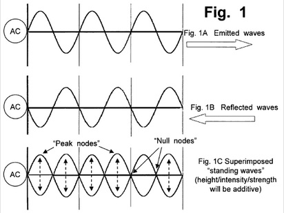
                In order to understand mutual inductance and therefore how longitudinal propagation arises within the secondary of the Tesla Magnifying Transformer it is crucial to understand how it relates to standing waves, especially the quarter wavelength component of a standing wave. First lets start with a stereotypical AC standing wave. A standing wave is created by sending a wave in one direction and then it REFLECTING back upon itself. Having a mirror like reflection point is key in order to create a standing wave. Image from Patrick Kelly.


                --->Starting Point ---------------- Reflecting point ----> |
                ------->>> Blue wave is the incident travelling in this direction ----->>>

                <<<------ Red Wave is the REFLECTED wave travelling in this direction <<<----

                The Standing wave is the resultant combination of the two opposing travelling waves. Superimposition. The red points are the nodes, the maximal swing point is the anti-node.

                I can't post the following animation here because it is a Java applet, however please click on the link and watch how a Standing wave is created in Slow Motion.

                Standing wave Java Animation

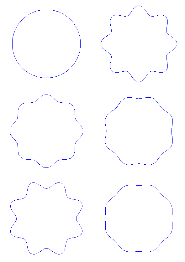
                Now if you were to take a top-down look at a single coil of which has a standing wave on it, it would look something like this:


                What is important to note is that at certain points along the perimeter of the circular wire there are massive voltage fluctuations, and NO voltage fluctuations at the nodal points.

                The secondary of the TMT has multiple loops of wire stacked on top of each other. So now imagine how if each one had a Standing wave on it what that might look like. If they are aligned it would look the same..or uniform all the way down. If the standing waves were out of sync, it would look more like a haphazard jagged saw blade. I believe the key to proper TMT tuning is to have all the nodes and anti-nodes on each winding line up with all the nodes and anti-nodes of the other windings. This in effect is that separate standing waves are synchronized with each other geometrically and spatially.

                The Importance of Quarter Wavelength:
                As O'Neill stated above, Quarter wavelength represents the maximum swing point. The point of greatest amplitude variation. These pictures show how a quarter wavelength is created. (Image from Patrick Kelly)


                Now the important thing to note here is that the TMT DOES NOT USE AC WAVES. Thus all the animations/pictures above are WRONG. They merely convey the concepts. Tesla used IMPULSES in his TMT to create standing waves/oscillation. These are quite a different animal than AC waves and look VERY different.

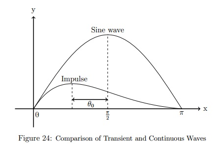
                Ok, so now what does a standing wave of quarter wavelength look like in a TMT? First lets relate how an Impulse wave compares to an AC sine wave.


                Notice how the 1/4 wave length is in a different spot for the impulse compared to that of the sine wave. This is very important because the maximum amplitude point is of crucial importance. The quarter wavelength for a sine wave is DIFFERENT than that of an impulse.

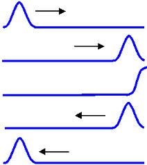
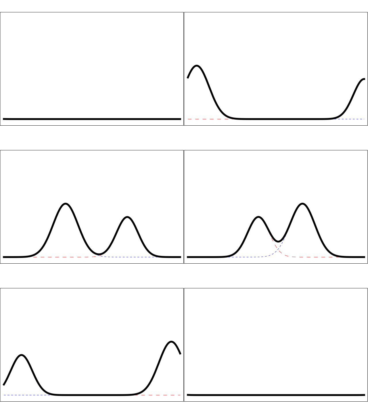
                Now this is more like how I Imagine an unidirectional impulse wave creates a standing wave. The forward wave and the reflected wave compound on each other giving power magnification. So not only is an impulse compress energy in time, when an impulse superimposes itself upon another impulse...well you get some massive power amplification.


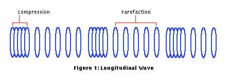
                A Standing Longitudndal wave in the aether or any medium such as a wire probably looks more like this.


                A Java Animation representation of the above - pleas click.

                What is important to note is the zones of compression is where maximum amplitude exists of the impulse wave. I hypothesize that the compression points are Peak L activity and Peak C activity in unison.

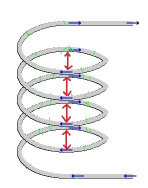
                Now if we look at a coil of winding like the secondary of TMT:


                The Red Arrows represent zones of compression or peak nodal points of Mutual induction (M) and Capacitance (C) from one impulse peak to another adjacent impulse peak, from one winding to another.

                It is hypothesized that the longitudinal waves travel orthogonal or at 90 degrees to the direction of propagation of the impulses along the wire. Thus in a way it might be likely to suppose that you have TWO standing waves here. One travelling along the wire, and another being created at 90 degrees.

                What's interesting here, and of course this all hypothetical talk, is that if Mutual inductance is occurring in counter space at 90 degrees to L then, it is directly in line with C. M and C are now in phase. The two lines of force are now geometrically aligned. M in counterspace and C in space. This is because the dielectric lines of force naturally jump across the space between the winding's, attaching themselves to the conductors on either side.

                This creates a rather interesting picture. We have a magnetic transfer of energy phenomenon happening in counterspace, and a naturally counterspaicial phenomena of Dielectric occurring in space. Regular L...magnetism appears to be left behind, and really is of only use to creating M. What happens with K!? Does that play a part in this?

                On a separate side note, I had to throw this in here:


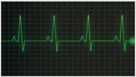
                That is an impulse waveform.....and it's a heartbeat! Nature as its source of power operates using impulses, not sinusoidal AC. Tesla was really onto something here. The impulse is another one of those fundamental archetypes of the universe.
                Last edited by Gestalt; 05-18-2012, 06:51 AM.
                A collection of Eric Dollards latest posts and writings on my website: Gestalt Reality - Eric Dollard

                Comment


                • Telluric Vs Hertzian propogation delay:

                  Have the Oscilloscope connected in an attempt to measure the propogation delay but difficult to do on Audio.
                  If the Station were to transmit a constant CW then it may be possible.
                  Radio & TV Stations in the old days used to transmit a CW after their close-down time at Midnight but don't think that happens today.

                  Tuned the Extra Coil and found the best to be 45 turns for my frequency.
                  However, tapping at this point lowers the signal and is much louder at the 55turn and unable to explain why.
                  A Portable Transistor Radio with an external dipole antenna goes very loud when placed near the Extra but one with an internal wound Ferrite type does not change volume.
                  Have now got the Primary with a variable Condenser (about 350pF) to join in with the symphony.
                  Will now make an Integrated Condenser.

                  Is anybody else able to pick up their Station with the 1N34 pick-up head
                  with an air gap from the Extra Coil and what distance can you first detect the Station and what is the loudest or best distance?
                  Thanks.

                  Smokey

                  Comment


                  • Originally posted by David G Dawson View Post
                    Is anybody else able to pick up their Station with the 1N34 pick-up head
                    with an air gap from the Extra Coil and what distance can you first detect the Station and what is the loudest or best distance?
                    Thanks.

                    Smokey
                    I have tried variuos extra coils and YES it starts to pick up around 6" away from the extra coil if I am touching any metallic part of the pick up headset. If I insulate myself from the headset it starts to pick up around 2" away. At contact it over powers the piezo and sounds garbled and scratchy.


                    @ Eric,

                    If you could give the following definitions new "words". That do not now, or have ever had any connection to the electrical world what would you call them.

                    C=
                    L=
                    K=
                    M=


                    Thanks,

                    Comment


                    • Originally posted by jake View Post
                      I have tried variuos extra coils and YES it starts to pick up around 6" away from the extra coil if I am touching any metallic part of the pick up headset. If I insulate myself from the headset it starts to pick up around 2" away. At contact it over powers the piezo and sounds garbled and scratchy.


                      @ Eric,

                      If you could give the following definitions new "words". That do not now, or have ever had any connection to the electrical world what would you call them.

                      C=
                      L=
                      K=
                      M=


                      Thanks,
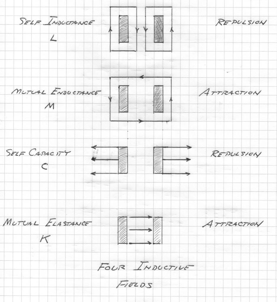
                      Here established is the forms of inductance, and two forms of capacitance. Expressing these in dimensional relations,

                      (1) L, Henry. Trasverse Inductance.

                      Centimeter Square

                      (2) C, Farad. Transverse Capacitance.

                      Second Square per Centimeter Square

                      And

                      (3) M, per Henry. Longitudinal Inductance.

                      Per Centimeter Square

                      (4) K, per Farad. Longitudinal Capacitance.

                      Centimeter Square per Second Square.

                      Hence given is the quadrapolar relations

                      L, the self inductance

                      C, the self capacitance

                      M, the mutual enductance

                      K, the mutual elastance.

                      Derived is two time scalar space distributions,

                      LM, Henry per Henry

                      CK, Farad per Farad

                      LM is called the Magnetic Space Factor,

                      CK is called the Dielectric Space Factor.

                      These space factors LM and CK represent this quadrapolar space distribution as extensions of the basic L and C. Also, a pair of frequencies now exist,

                      LC, Henry – Farad, or Second Square

                      And

                      MK, per (Henry – Farad) or per Second Square.

                      It hereby can be seen that resonance of a complex structure, such as an oscillating coil, is much more difficult to represent than a simple LC relationship. Here is the major obstacle to the engineering of Tesla type resonant transformers.

                      Break more to follow
                      DE N6KPH
                      Mandatory ten letters here...
                      Last edited by Web000x; 05-18-2012, 06:15 PM.

                      Comment


                      • Inductive Waves

                        Previously defined are four dinstinct electric types of inductivities:

                        1) Self inductivity, L, in Henry per centimeter
                        2) Self capacity, C, in Farad per centimeter
                        3) Mutual enductivity, M, in per Henry per centimeter
                        4) Mutual elastivity, K, in per Farad per centimeter

                        The dimension relations are given as:
                        1) L, centimeter
                        2) C, second square centimeter cube
                        3) M, per centimeter cube
                        4) K, centimeter per second square

                        These are the distributed constants of the generalized field of electric induction. The two distributions in space are defined by:

                        1) LM, per centimeter square
                        2) CK, per centimeter square

                        Dimensionally standing between LM and CK is the dimensions of second square. This is to say that the magnetic distribution and the dielectric distribution are interwoven through the dimension of time and its relation frequency. This is not unlike a simple condenser and reactance coil which interect through per second square. Now the two fields are not lumped, but are distributed in form. Hence the time dimensional interactions between LM and CK gives rise to a complex of electric wave propogations in both spatial and counter spatial modes.

                        Here we meet with the completely generalized electric wave. We are nearing the holy grail of electrical engineering.

                        The complex of magneto-dielectric interactions can take four distinct forms. Each is a single magnetic energy interacting through time with a single dielectric energy. Hence:

                        1) LC, Henry-Farad per centimeter square
                        2) MK, per Henry-per Farad per centimeter square

                        In dimensional expression these are given as,
                        LC, second square per centimeter square
                        MK, second square times centimeter square

                        These two terms give rise to a pair of propogation constants,
                        One over the square root of LC,
                        1) centimeters per second

                        One over the square root of MK,
                        2) per centimeter per second

                        Relation (1) is a velocity, motion through space over time, and relation (2) is a counter velocity, motion through counter space over time. These two propogation constants represent the motion of electric induction in a general metallic-dielectric geometry. Unlike the distributions LM and CK which are hyperbolic functions of distance, the propogations LC, and MK, are circular functions of distance along the propogating structure. It can be said two hyperbola are transformed into two circles, this as a geometric analog.

                        Two additional interactions between magnetic and dielectric inductions arise,
                        3) K/L, per second square
                        4) M/C, per second square

                        or alternatively
                        3) L/K, second square
                        4) C/M, second square

                        A reciprocal relation suggests itself here such as
                        3) L/K per second square
                        4) C/M second square

                        In all their forms both L over K and M over C are space scalars in that they exhibit no distribution in space, everywhere at the same time. Relations (3) and (4) are space-scalar frequencies of magnetic-dielectric exchange and accordingly they are circular functions of time.

                        Through the presented dimensional relations a generalized expression for electric induction is established. It consists of the following components,

                        1) The space distribution of magnetic induction, LM,
                        2) The space distribution of dielectric induction, CK,
                        3) The time rate of energy exchange between self inductivity, L, and mutual elastivity, K,
                        4) The time rate of energy exchange between self capacity, C, and mutual enductivity, M

                        And these four factors, or constants give rise to a pair of electric wave propagations,

                        a) The electromagnetic propogation in space, LC,
                        b) The magneto dielectric propogation in counterspace MK

                        Here four scalar constants, two time scalar, two space scalar, give rise to a pair of waves in two conjugate dimensional relations. This is a bit more complex than a single lumped condenser, or a single lumped reactor. In fact in view of this more generalized understanding the condenser is in actuality a mutual elastor, K, and the reactor is in actuality a mutual enductor, M. Here is a completely reversed viewpoint.

                        73 DE N6KPH
                        SUPPORT ERIC DOLLARD'S WORK AT EPD LABORATORIES, INC.

                        Purchase Eric Dollard's Books & Videos: Eric Dollard Books & Videos
                        Donate by Paypal: Donate to EPD Laboratories

                        Comment


                        • SUPPORT ERIC DOLLARD'S WORK AT EPD LABORATORIES, INC.

                          Purchase Eric Dollard's Books & Videos: Eric Dollard Books & Videos
                          Donate by Paypal: Donate to EPD Laboratories

                          Comment


                          • Once again Thank you Eric,

                            I do hope to make some progress on reading the lecture notes, your notes and references. Full load of work here, I'd say that there is easily 4~6 yrs of study and research to cover.

                            I wanted to comment on the hyperbolic curves, going to a Poincare disk model or hyperbolic geometry the hyperbola can be the inverse of a sphere depending on projection and plane.


                            Uploaded with ImageShack.us

                            I've been working on spherical waves for the electrostatic field, two intersecting spherical waves would have a hyperbolic curve in counter space.

                            William Clifford developed an Algebra for hyperbolic geometry. In his book Elements of Dynamic (1878), he introduced "quasi-harmonic motion in a hyperbola". He wrote an expression for a parametrized unit hyperbola.

                            I'll try and dig this up and post it here later.

                            Comment


                            • There seems to be little progress in the longitudinal moon bounce idea, this because we do not know what it is that is bouncing off the moon or if it even bounces at all. It seems necessary to go back to "square one".

                              It was said that you cannot see the stars in outer space. Is there some reason why you should see them? If then there is no primary light in outer space beyond the influence of the earth then there is no velocity of light since there is no light. This is to say there is not a delay in time when viewing objects in deep space, no light years, etc. The distant galaxies then appear here just as they are, not images of a distant past. Relativity crashes into oblivion. What is known on earth as light is electro-magnetic waves. These light waves of course propagate at luminal velocity.

                              The sun and stars in this view emit primary induction, not electro-magnetic waves. This is to say that while man made waves that take 8 minutes to travel from sun to earth, the primary induction of the sun arrives at earth much sooner, if not instantly. It is the envelope of the earth itself that engenders the sun light. Through a better understanding of this primary induction a transmission system utilizing it can be developed. The idea here is NOT to get too hung up on theory and innumerable details but to make something work, and this is in the face of impossibility. This is like a military situation, make it work or the ship sinks. The Navy has no secret Telluric system, and moreover they gave up on E.L.F., 76 cps.

                              Marconi just does not work at those frequencies. If there was such a Navy Telluric transmission, it would be received at Landers. The Landers antenna was capable of detecting underground nuclear detonations, and the Navy 25 Kc/sec fleet broadcast was overwhelmingly strong, requiring the use of band reject networks. Break, more to follow

                              SUPPORT ERIC DOLLARD'S WORK AT EPD LABORATORIES, INC.

                              Purchase Eric Dollard's Books & Videos: Eric Dollard Books & Videos
                              Donate by Paypal: Donate to EPD Laboratories

                              Comment


                              • [QUOTE=jake;193694]I have tried variuos extra coils and YES it starts to pick up around 6" away from the extra coil if I am touching any metallic part of the pick up headset. If I insulate myself from the headset it starts to pick up around 2" away. At contact it over powers the piezo and sounds garbled and scratchy.

                                Jake,
                                Thankyou.
                                20" here with best at 8" without me being bodily present in any way and comes in loud and clear.

                                Have made a Math presentation at 'n6kph' and will copy here later.

                                Have been able to improve the Oscilloscope view and have taken some 30 or 40 pictures and will sit down to review.
                                You can see a slight misalignment but may not be sufficient to generate a propogation delay time.
                                Oscilloscope is a HP 1741A 100 Mhz.

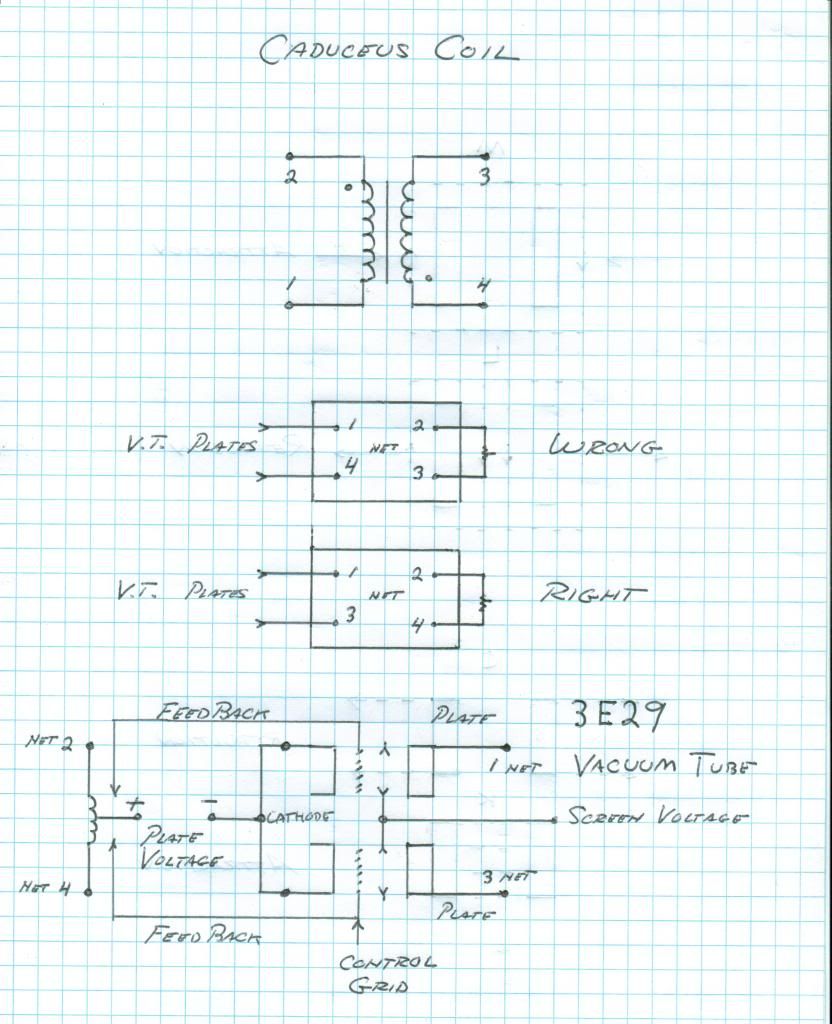
                                Eric's 3E29 data sheet:

                                http://www.mif.pg.gda.pl/homepages/f...049/3/3E29.pdf

                                Thought I had one but not the case.

                                Smokey

                                Comment

                                Working...
                                X