Announcement

Collapse
No announcement yet.

Eric P. Dollard

Collapse
This topic is closed.
X
This is a sticky topic.
X
X
 
  • Filter
  • Time
  • Show
Clear All
new posts

  • Soviet Union Handshake?

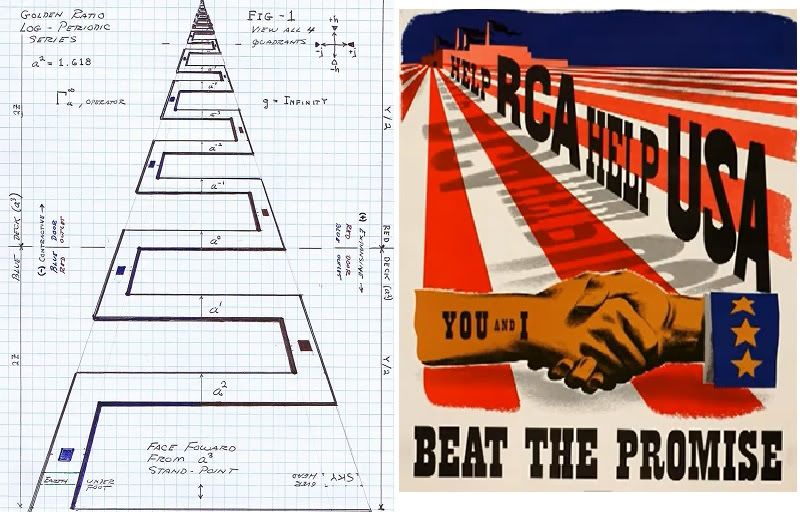
    I noticed a large red and white R.C.A. image as shown on youtube(The Story of RCA and the death of the Marconi Wireless System - YouTube) with me talking in the background. While I love the "Eastern block" image WHY am I being involved in it? Can anyone TELL ME?

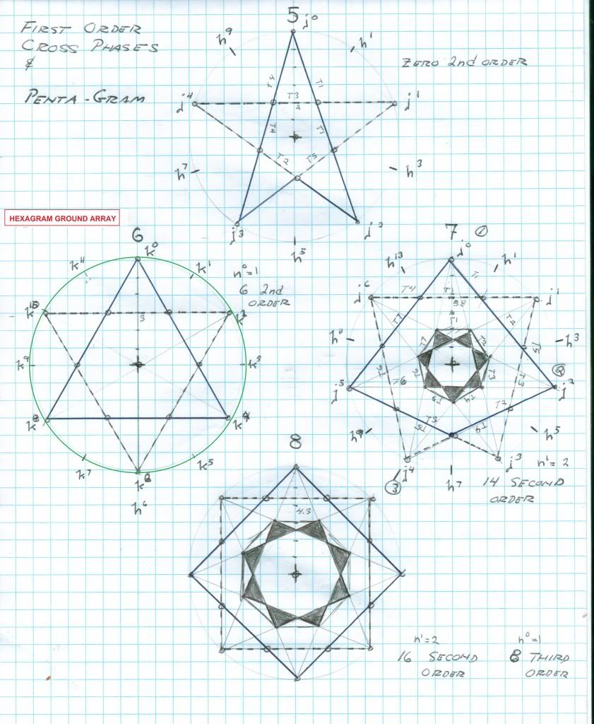
    As I have said before the R.C.A. station in Bolinas is a massive cover-up. A gigantic hexagram 1000 ft in diameter is buried under the Marconi building. It was Marconi's earth terminal and looks to be radionic also. I sent the blueprints to Borderland and you can guess what happened, yes, "just like a fart in the wind"! Gone.

    Two major historical reports, books actually, were produced, one by Dewy Livingston, "Wireless Giant of the Pacific", and one by Eric Dollard, "Electric Wave Telegraphy". Both books and all records are kept secret at the Point Reyes national sea shore headquarters in Olema, California. This is a good use for the Freedom of Information Act, who can or will do this? It is also important to note that the Rockefeller's came out with a P.B.S. documentary called "Empire of the Air", it is a must to watch this video, even if it's a P.B.S. cover-up story. Through the careful study of the "Iron Grip" held on the Bolinas-Marconi, R.C.A. station it will reveal who is blocking our knowledge of the works of Nikola Tesla and his contemporaries. It is the "Commonweal".

    73 DE N6KPH

    Front page of the "Phoenix Liberator" previously referenced

    SUPPORT ERIC DOLLARD'S WORK AT EPD LABORATORIES, INC.

    Purchase Eric Dollard's Books & Videos: Eric Dollard Books & Videos
    Donate by Paypal: Donate to EPD Laboratories

    Comment


    • Principles of Perspective

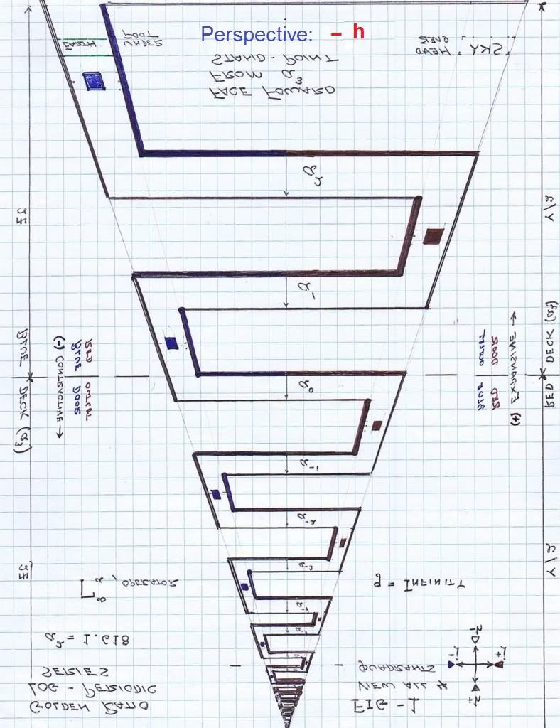
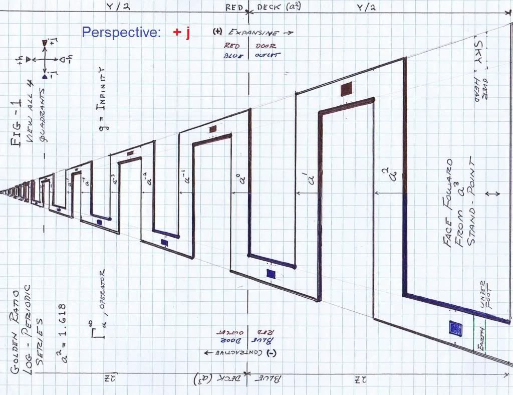
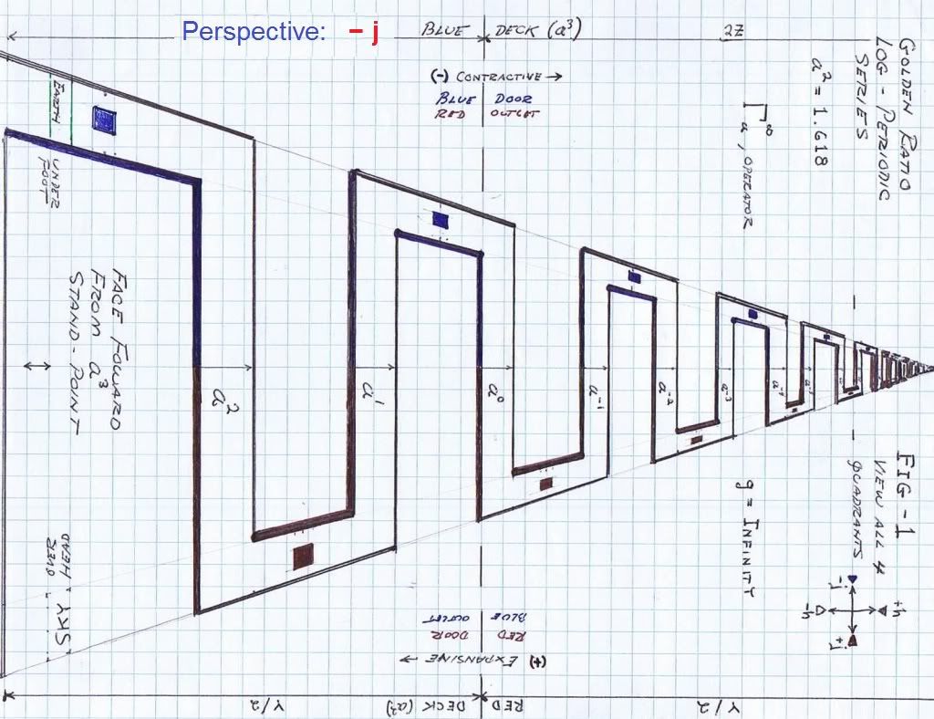
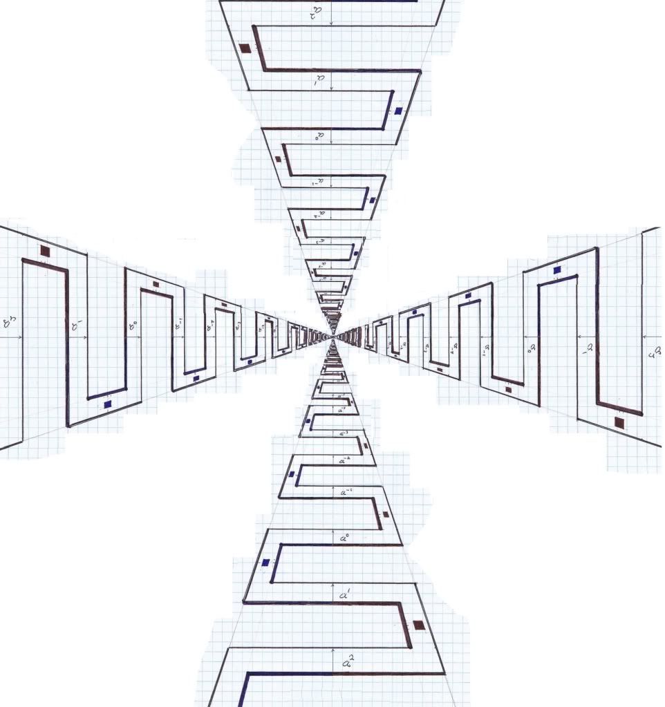
      Going back to some previous material, the golden log periodic series. The diagram was meant to be viewed in 4 directions, the 4 quadrants:


      The 4 phase end fire log periodic array. If strips were cut out of metal it would form a log periodic antenna. The beam direction is the apex and it's circularly polarized. The antenna to infinity?


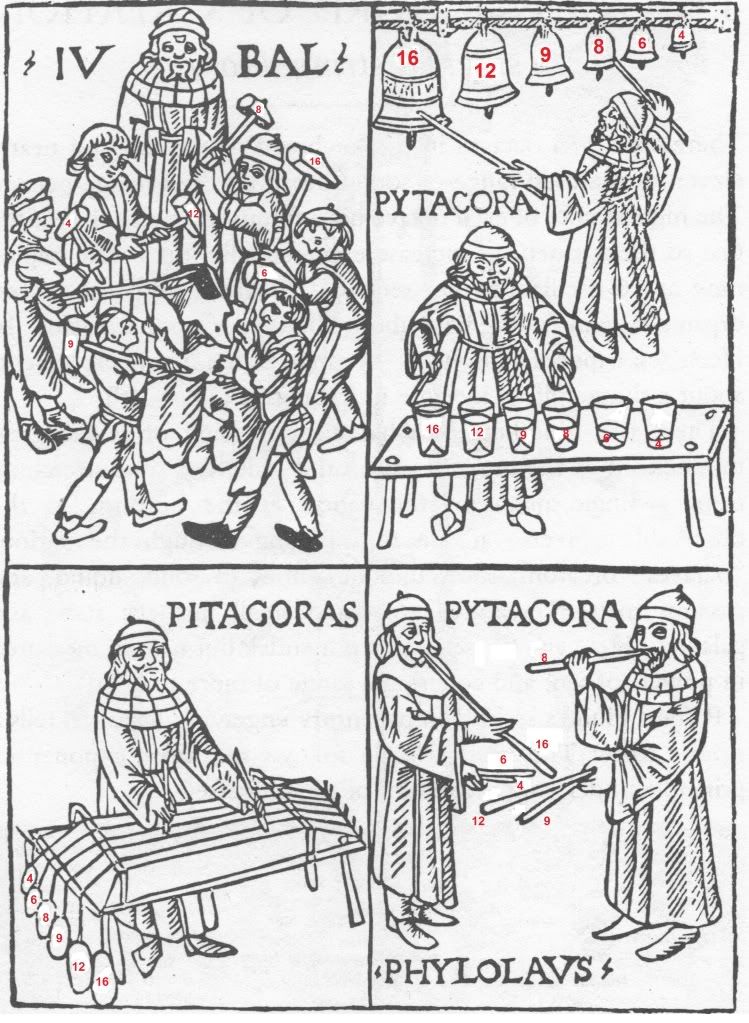
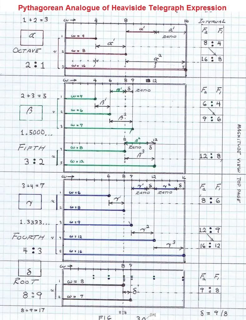
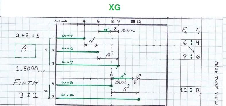
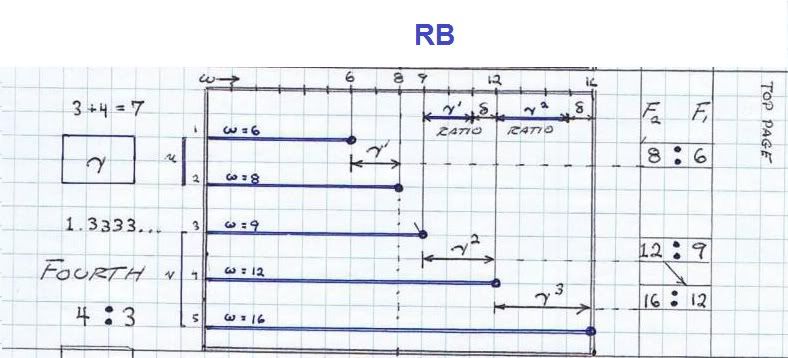
      The Pythagorean Number Series:


      SUPPORT ERIC DOLLARD'S WORK AT EPD LABORATORIES, INC.

      Purchase Eric Dollard's Books & Videos: Eric Dollard Books & Videos
      Donate by Paypal: Donate to EPD Laboratories

      Comment


      • Integratron, Final

        The group of people that were involved with the Integratron devolved into the space brother UFO Nazi conspiracy from Ashtar Command and channeling Hatton, the Phoenix Liberator. It contains some truly outrageous material to read.

        The Van Tassel time imaging is based upon the idea that Earths Magnetic field has a permanent memory, time scalar so to speak. His coils, last seen with Chris Carson were like ferrite loopsticks with cross wound coils, crossing at an agle of 22.5 degrees. Loopstick antenna into time? These coils were connected different than the space scalar Caduceus coil I just wrote on. These as time scalar would use the connection marked "wrong", which is now "right" in the time mode. Do not know any more without actual experiment.

        More pictures of the Phoenix Liberator, previously they were called the Phoenix Express. Additional articles can be found at:
        The Phoenix Archives -- The Phoenix Liberators - 1991


        73 DE N6KPH
        Last edited by t-rex; 05-30-2012, 10:36 PM.
        SUPPORT ERIC DOLLARD'S WORK AT EPD LABORATORIES, INC.

        Purchase Eric Dollard's Books & Videos: Eric Dollard Books & Videos
        Donate by Paypal: Donate to EPD Laboratories

        Comment


        • Have you called your Congressman today?


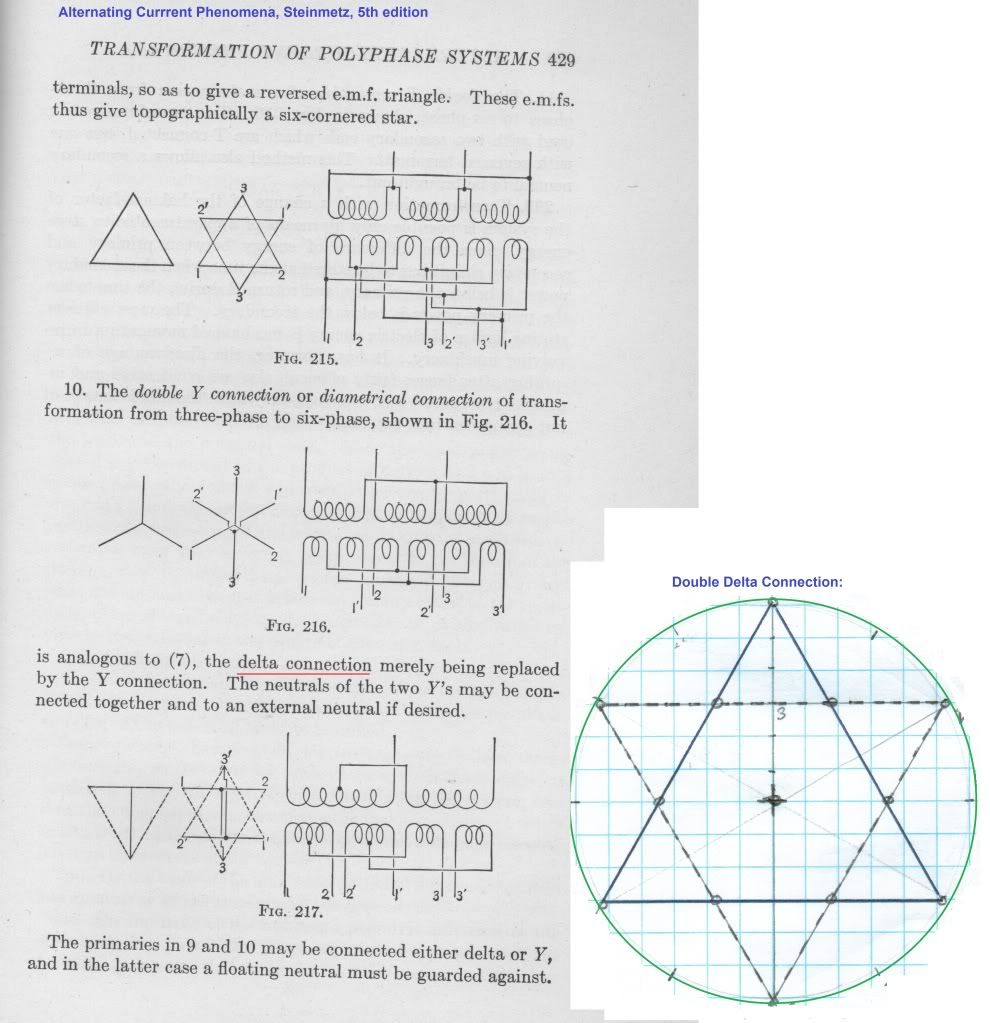
          Bolinas Marconi underground radionic antenna, geometry of ground array underneath Marconi building:


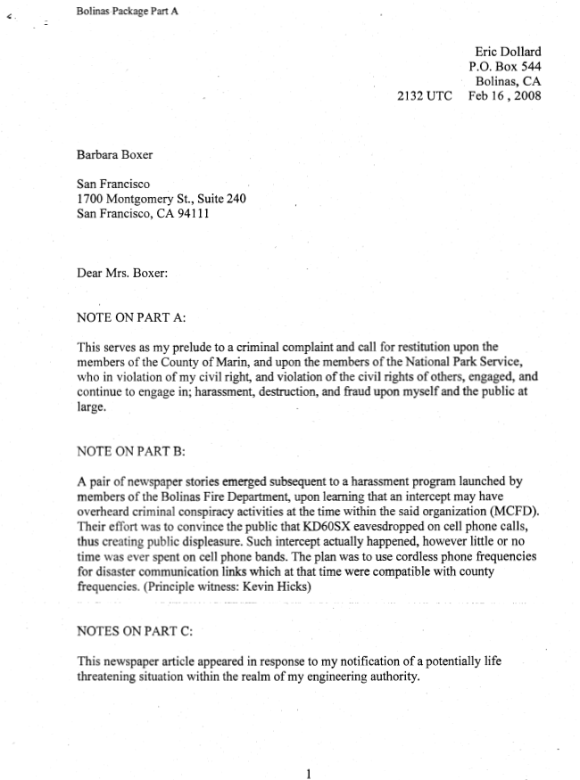
          The Barbara Boxer Report(Eric Dollard - Bolinas Incident


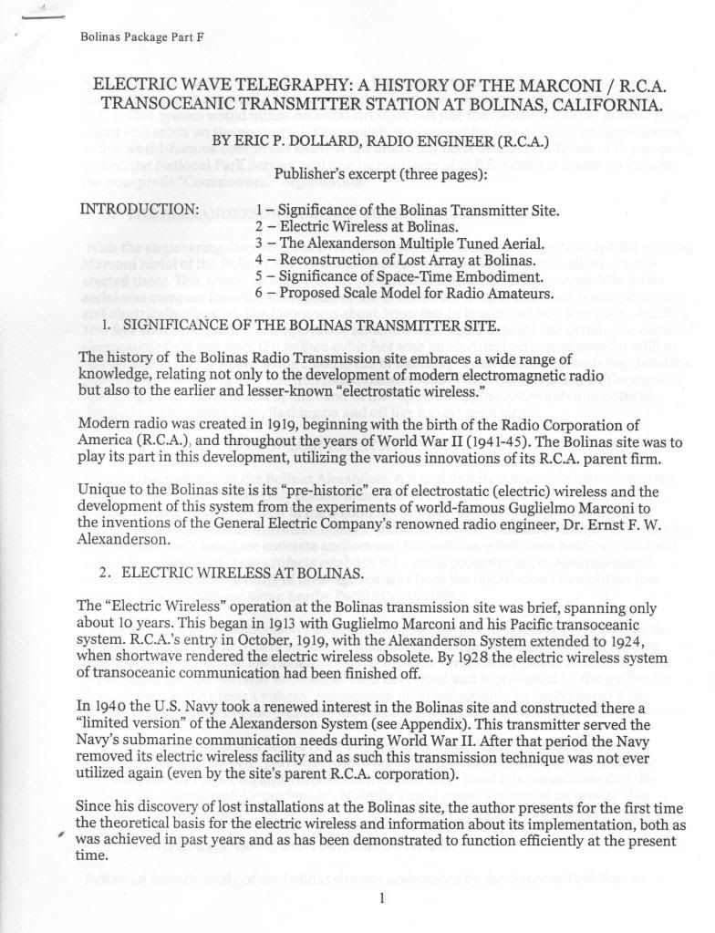
          This is the beginning of the censored Eric Dollard RCA book:


          73 DE N6KPH
          SUPPORT ERIC DOLLARD'S WORK AT EPD LABORATORIES, INC.

          Purchase Eric Dollard's Books & Videos: Eric Dollard Books & Videos
          Donate by Paypal: Donate to EPD Laboratories

          Comment


          • SUPPORT ERIC DOLLARD'S WORK AT EPD LABORATORIES, INC.

            Purchase Eric Dollard's Books & Videos: Eric Dollard Books & Videos
            Donate by Paypal: Donate to EPD Laboratories

            Comment


            • I'm embarking on a new project, a smaller replication of Eric's Cosmic Induction Generator. I received this book in the mail today. It and a copy of the "Radio Amateur's Handbook" contain all the information necessary to complete the build. I will update as I make progress

              Please help support my indiegogo campaign: Cosmic Induction Generator

              Comment


              • Trideco VLF Antenna

                Originally posted by T-rex View Post
                Double Delta Connection is said to be a 'Trideco'.
                Have attached Google Earth Photo of Harold E Holt VLF Communication Station at North West Cape in Australia.
                This station was handed over to Oz Navy several years ago but is now controlled/operated by Raytheon since 2011:

                Naval Communication Station Harold E. Holt - Wikipedia, the free encyclopedia

                There is also a listing of VLF Stations from 20 to 25Khz but most of these now appear limited in use or not used at all because of Satellite Communications:

                RADIO SIGNALS IN THE RANGE; 20 - 25 kHz

                Notice how fragile all communications now are, being dependent on satellites and solid state technology which to me lacks substance and why I have reverted back to the olde.
                One lousy EMP and it no longer works.
                Interesting Stuff!

                Smokey
                Last edited by David G Dawson; 06-19-2012, 08:21 AM.

                Comment


                • Cosmic Induction Generator

                  Jpolakow,
                  Excellent!
                  Would like to do the same but focussed on 'Enhanced Energy' (EE) and hoping Eric can direct us to it through experiment.
                  'Zero Point Energy, 'Free Energy' and 'Over Unity' are all now defunct and have chosen 'Enhanced Energy' as a more suitable description.

                  You could have obtained a copy of RCA TT-5 from here:

                  http://w5jgv.com/downloads/RCA-TT-5.PDF

                  Lots more information here:

                  Technical books online by dxzone.com

                  Let me know if you need help as Vintage Radio is what I do when not involved with seeking EE.
                  Still rebuilding the Yaesu FT 901D Transceiver here which would make a good driver for the CIG.
                  Have many schematics for base Drivers and Linear Amplifiers and looking at building the Linear in the near future.
                  Do you have a start schematic as yet and what Tubes will you be using?

                  Smokey

                  Comment


                  • Originally posted by David G Dawson View Post
                    Would like to do the same but focussed on 'Enhanced Energy' (EE) and hoping Eric can direct us to it through experiment.
                    'Zero Point Energy, 'Free Energy' and 'Over Unity' are all now defunct and have chosen 'Enhanced Energy' as a more suitable description.
                    Smokey,

                    This quote is taken from this thread: http://www.energeticforum.com/renewa...m-papalex.html
                    Originally posted by Web000x View Post
                    Hey Garrett,

                    Thanks for starting this thread. I do not plan on becoming too active in discussion since I have experiments to run but figured that I would show some promising results regarding parameter variation. I have built a machine that consists of two alternators and a prime mover. The alternators are spinning at a ratio of 1:2 to give me a primary frequency and the 2nd harmonic of that frequency as per the instructions of Manelstam & Papalex, E.P. Dollard, and Steinmetz.

                    I am only using junk parts for my magnetic amplifier. It consists of laminations carefully chiseled away from a microwave oven transformer to equal roughly the same density as the iron in my alternator. The power windings of the magamp have been matched to the copper for a single phase in the alternator.

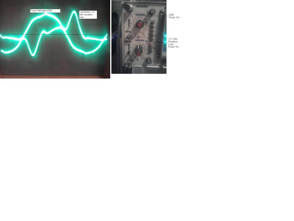
                    When I modulate the inductance of the magamp's power winding at the correct phase angle via the control winding, I get a waveform that looks like this:


                    Sorry about the small picture but I don't have time to go back and make it better.

                    Notice the positive power (Ei) relations versus the negative power (-Ei) relations. They seem to be of approximately the same as far as the energy storage and the energy return goes. The noteworthy component is the 1.5 ohms worth of resistance that the current is "flowing" thru each time, lighting the car headlamp to a brightness that I don't like to stare at. This is all being done for 13 watts worth of modulation from the 2nd harmonic wave which has much more room for increases in efficiencies.

                    By no means have I analyzed this as extensively as one would need to for a thorough scientific analysis, but it sure is interesting to see the beginnings of what has been proposed by the pioneers.


                    Dave
                    What you must do for your 'Enhanced Energy' is find a core material that has a square hysteresis loop (Metglas looks good but costs too much for me). You will need to wind copper wire on this core in a magamp configuration. Modulate the control winding at twice the frequency of the power winding's frequency. Eric said that finding the right material is going to be the biggest challenge.

                    More on this can be found in the T-Rex posts on parameter variation.

                    Dave
                    Last edited by Web000x; 05-31-2012, 03:25 AM.

                    Comment


                    • Mr. Dollard,

                      regarding the blocking of Nikola Tesla's work I think that the situation is part of a much larger picture.

                      I am not an anthroposophist, but I do agree deeply with some things that Rudolf Steiner wrote about. Especially regarding Goethe and his ideas concerning natural sciences. The path on which we have been for the past 120 year is exactly opposite to that of Goethe.

                      I came to Steiner through Goethe and Tesla. This is what both have in common. Goethe, namely.

                      Now, the following two texts show the future development of our world, if something does not change soon:

                      1.) Ingo Hoppe: The Machine-Planet - Our future? (Autumn 2000)

                      2.) The Future of Black Technologies (La Huitième Sphère: The Future of Black Technologies)

                      Our modern societal, technological and economical systems are profoundly hostile to man as a human being.

                      Cousin Itt

                      Comment


                      • Originally posted by David G Dawson View Post
                        Jpolakow,
                        Excellent!
                        Would like to do the same but focussed on 'Enhanced Energy' (EE) and hoping Eric can direct us to it through experiment.
                        'Zero Point Energy, 'Free Energy' and 'Over Unity' are all now defunct and have chosen 'Enhanced Energy' as a more suitable description.

                        You could have obtained a copy of RCA TT-5 from here:

                        http://w5jgv.com/downloads/RCA-TT-5.PDF

                        Lots more information here:

                        Technical books online by dxzone.com

                        Let me know if you need help as Vintage Radio is what I do when not involved with seeking EE.
                        Still rebuilding the Yaesu FT 901D Transceiver here which would make a good driver for the CIG.
                        Have many schematics for base Drivers and Linear Amplifiers and looking at building the Linear in the near future.
                        Do you have a start schematic as yet and what Tubes will you be using?

                        Smokey
                        Hi Smokey,
                        Thanks for the reply. Just for reference Eric prefers the term "Energy Synthesis" to "Free Energy", "Zero Point Energy", or "Overunity". The other terms are associated with charlatans and non-working devices.

                        Yes I was aware the book was available for free download. For me at least, it is difficult for me to absorb information from a book by reading it on a computer, so I try to get a hard copy whenever possible. My main purpose of posting an image of the book was to show the similar coloring between the book and the propaganda poster. I thought it was interesting. Eric previously mentioned to me in the past that this book was a necessary resource for the building of the CIG.

                        Thank you for your offer of help with the CIG. I'm sure I will need it! Previously Eric had given some advice for the design, scaled down from his 5 kw/3 phase version. I will be building a 1 kw single phase unit. The Tesla Transformer portion of it will closely correspond with the coils used in the Crystal Radio Initiative. So far I'm still working on mapping out the power supply portion of it, don't have a schematic yet. Previously Eric had helped me pick out the required filament transformers, swinging chokes, filter chokes, etc etc. There are a lot of transformers required! The swinging chokes seem to be the most difficult to find(in the specs needed), I've already acquired one of the high voltage transformers. The tubes have mostly been selected, will post more later this weekend.

                        I plan on posting everything as I go along, so others can follow and replicate if desired(assuming I get it to work). Also to get help from you guys, as I have very little experience with vintage radio equipment. Eric will be able to help out with advice whenever he comes around. I plan on posting everything so whatever mistakes are made will be avoided by others. Will keep updated...


                        John
                        Please help support my indiegogo campaign: Cosmic Induction Generator

                        Comment


                        • Hi SERG V:
                          I don't want to sound like a pest, but it is customary to indicate the units for quantities and for equations. Just because you know it does not mean it is obvious to others. For instance I do have precision caps with pF, nF and uF values. Also to my other post you indicated to just grab a bunch of capacitors and try. It would be helpful to give some starting values. Otherwise thank you for sharing this method.

                          Comment


                          • Force on an aAsymmetric Capacitor?

                            During my research on the theory E. Dollard presents, I ran across the following report (well, I did some active searching, but Eric's theory inspired me to):

                            Force on an Asymmetric Capacitor
                            ... and here's a direct link to the PDF report.

                            Shortly put, it is claimed that when having a smaller top plate and a larger bottom-plate, then applying >20 kV on these will result in a force in the direction of the smaller plate, regardless of polarity.

                            So, has anyone heard about this phenomenon before? And is this something that you could explain with your theory, Eric? As far as I know nobody has succeeded in explaining this using established theory (me included).

                            Comment


                            • Asymetric Capacitor

                              Fefish,

                              I may not be an engineer or physicist by trade, however, I have studied these matters enough that I might be able to give a possible solution to the question. Although I will most likely be wrong, here's how I see the situation:

                              If we look at the dielectric circuit in question, your asymmetric capacitor, we will notice that we have two different surface areas on each bounding conductor of the circuit. If we go "old school" we can say that dielectric energy is NOT directly due to electrons but instead lines of coulombs stored in the dielectric, be it air or some other insulator. These lines terminate on the intermolecular corpuscles called electrons (for the negative lines). Subsequently the field terminates on the SURFACE of the conductor, and more specifically the end-terminal electrons at the conductors surface.

                              Now if we have a very High Voltage dielectric circuit with asymmetric fields, with air as the dielectric, we will engender too many field lines on one side of the circuit than the other. We will also have a problem of dielectric saturation of the air. If the lines of induction cannot move freely, due to being bound to the surface of "charged particles". Then the only way they can contract is to pull any free to move charge carriers. Ideally the lines of dielectric induction want to be a singularity or infinitely short in length.

                              The physical force seen is due to the contraction of the lines of induction by PULLING on the ions formed in the air due to dielectric saturation or other free to move charged particles. If we examine the plates of the capacitor we will notice a great dielectric density D around the small plate and a lesser density around the large plate. If we go back and remember that similar field lines like to distribute evenly along a smooth uniform surface, and that like lines repel one another, we will start to see that the large plate has extra field lines that cannot terminate on the smaller plate. It is these lines that cause the mechanical forces seen in the direction of the smaller plate. The field lines are trying to reach a state of equipotential. But, they cannot achieve that due to the ions being free to move, thus it is in a constant state of imbalance where equalization of the field lines can never be made manifest. You should also be able to observe an "imaginary" extension of the smaller plate as a conductive plasma around its periphery, this is the natural result of dielectric saturation and equipotential equalization of field lines.

                              I should point out that the collapsing field lines due to ion flow, requires a constant current, due to the dielectric consumption taking place. Also, the free flow of charged particles will engender HEAT and possible damage to the terminal surface of the capacitor plates seen as pitting from bombardment, so don't fool yourself into thinking there are no losses or practical problems.

                              Also, there is NO "free energy" here, but maybe an interesting way to produce a unidirectional mechanical force by a constant current.

                              Once again, this is my crude attempt at explaining something that I am definitely not well versed in, but at least its a reply and may possibly help,

                              Garrett M
                              Last edited by garrettm4; 06-03-2012, 02:16 AM.

                              Comment


                              • Pulse Generators, etc

                                (1) The Guillemen line, or network, can be regarded as an elementary electro-static condenser. It has two terminals, and stores electro-static, or dielectric, energy. this in a manner like the basic condenser. There is one important difference however, this "Guillemen Condenser" is a "loaded condenser".

                                The common condenser discharge is of a hyperbolic nature, this in Nepers per second. This is not a pulse, it is an impulse. The variation of a pulse is indefinite in time or a discontinuous function, not a hyperbolic one. The hyperbolic function is a result of a rate of change of a quantity which at each instant is proportional to the magnitude of the quantity itself. This gives rise to Epsilon, or base e natural logarithms. It is a law of energy and thermodynamics. The pulse, in distinction to the impulse, represents a constant flow of electric energy, hence constant power.

                                (2) Previously discussed was the loading on antenna and long distance telephone lines. For the most part the networks described were all four terminal structures, with the exception of reactance arms. The output terminals were the distant telephone, or the Aether itself. The Guillemen network is a two terminal structure and cannot be considered a transmission network as normally understood. Now it is a transmission network in a counter spatial form. So as with a loaded electro-magnetic telephone pair, a four terminal network, the Guillemen line is a loaded dielectric network, a two terminal network. In his book "communication networks", volume 2, Guillemen is close to a wave equation for counterspace. The "Type A" line can be considered a longitudinal magneto-dielectric transmission line. This is important.

                                (3) For pulse experimentation I recommend the 2050 Argon Thyratron, this instead of a 5C22. Likewise, a 5R4G dual half-wave rectifier can replace the pair of 705 H.V. diodes. This is where to start.

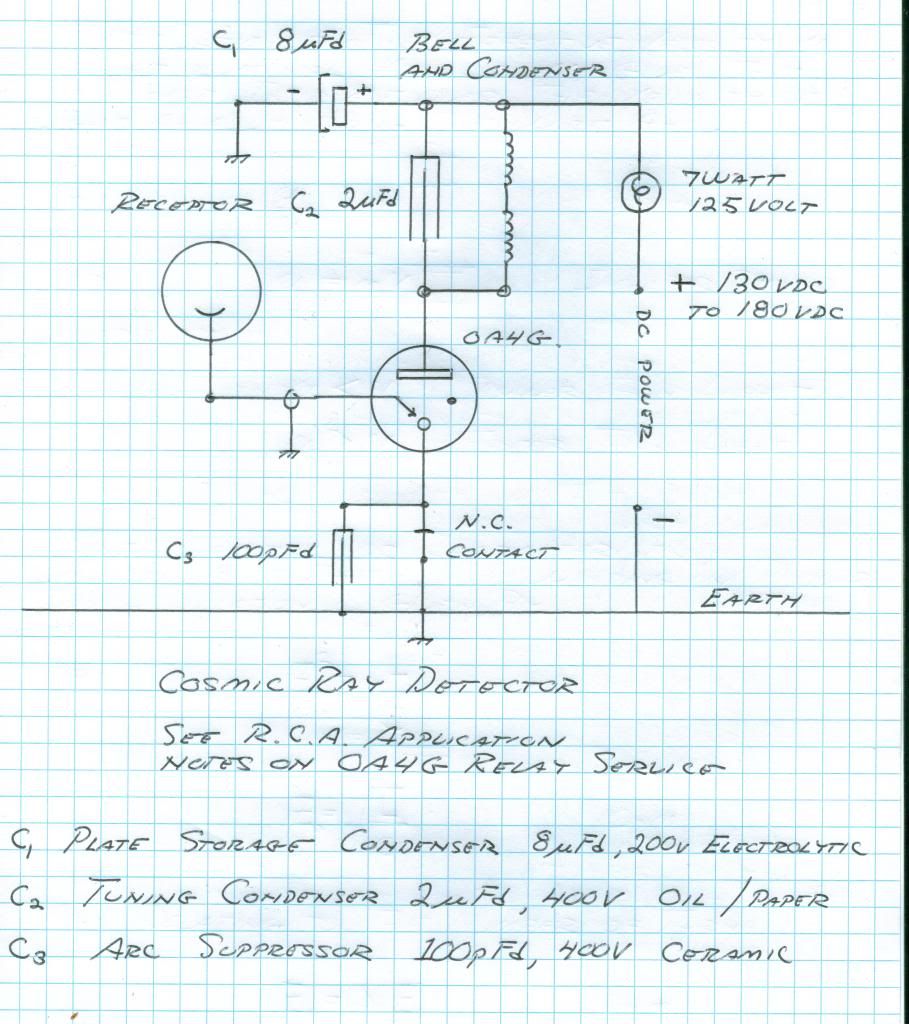
                                The OA4G has application as a radiant matter detector. The main circuit consists of a Western Electric Telephone Bell in series with the plate supply. The bell condenser should be connected in shunt to the bell windings. A contact should be fitted to the bell armature to break the cathode connection to the OA4G in order to reset the tube. See the Marconi Coherer detector.

                                (4) Th cosmic anode lead connects to the trigger or grid lead of the OA4G. There must be NO DC leakage to ground. For cosmic anodes see Vassilatos "Vril Compendium", and the experiments of Luigi Galvani.

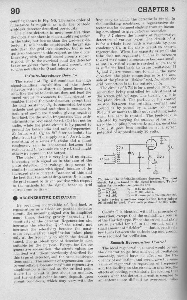
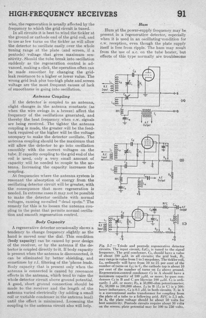
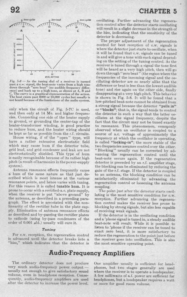
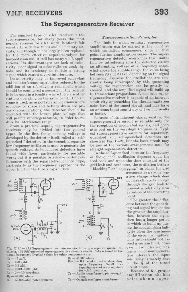
                                (5) As for detectors into the outer limits the common regenerative detector is the circuit of choice. It is a development of E.H. Armstrong, see "Empire of the Air". The Regenerative Detector is also developed in the Russian parametric paper, an important study. Radionic receivers here are possible, depending on the metallic-dielectric geometry used. Connection with a magnification transformer is possible.

                                Finally, the bulbs. The neon sign shops receive their gas in large glass globes. It is at a bit less than atmospheric pressure and when exhausted it of course is at the same pressure as the neon tube under construction. These bulbs then are junk to the neon guy. Great glom potential! These bulbs can be pumped further with a diffusion pump and a small ion gun can be placed in its neck, or a Tesla electrode fitted inside. Many possibilities.

                                (6) So sell your Bedini junk off on e-bay to the Chinese. Dispense with the Grey tube secrets and the rest of the useless lot. These are only dummy loads to tax your resources and keep your mind chasing its own tail. It is established here that the old "Electrical Experimenter" can come back to life, the possibilities are infinite.

                                73 DE N6KPH


                                SUPPORT ERIC DOLLARD'S WORK AT EPD LABORATORIES, INC.

                                Purchase Eric Dollard's Books & Videos: Eric Dollard Books & Videos
                                Donate by Paypal: Donate to EPD Laboratories

                                Comment

                                Working...
                                X