Announcement

Collapse
No announcement yet.

Eric P. Dollard

Collapse
This topic is closed.
X
This is a sticky topic.
X
X
 
  • Filter
  • Time
  • Show
Clear All
new posts

  • Originally posted by garrettm4 View Post
    You should also be able to observe a "imaginary" extension of the smaller plate as a conductive plasma around its periphery, this is the natural result of dielectric saturation and equipotential equalization of field lines.
    That seems as a very reasonable explanation, thanks! The only "problem" is that this phenomenon is claimed to occur in vacuum as well, however with a smaller force (maybe it's just due to the much smaller, but still not zero, amount of particles in a vacuum).

    Originally posted by garrettm4 View Post
    I should point out that the collapsing field lines due to ion flow, requires a constant current, due to the dielectric consumption taking place. Also, the free flow of charged particles will engender HEAT and possible damage to the terminal surface of the capacitor plates seen as pitting from bombardment, so don't fool your self into thinking there are no losses or practical problems.

    Also, there is NO "free energy" here, but maybe an interesting way to produce a unidirectional mechanical force by a constant current.
    No, actually I never thought of it that way. What I found fascinating however, was that if it is possible to make the force much stronger than in the mentioned experiment (by optimizing capacitor design, voltage, etc), then you would get what some would call an "UFO". And as I do not believe UFOs being an alien thing, but rather (if at all) a secret military technology, this gets all the more interesting, as this might be that hidden technology. What made me do this connection was that in the report, it was stated that what accompanied the experiment was a "hissing" sound (not weird at all, I know), and that made me wonder if there were any sounds reported to be heard during so called UFO sightings... and there were; "hissing" sounds. These are just speculations, but nonetheless interesting ones, at least if you ask me.

    /fefish

    Comment


    • "Free energy"?

      I have been wondering this for a while, and garrettm4's mentioning of the term "free energy" above reminded me of asking the following.

      Simply put: what is the "promise" of a power transmitting Tesla Coil? Is it "just" the wireless power phenomenon, or is there any "overunity" effect or whatever you would like to call unexplained(?) energy gain (i.e. more electrical energy out than in)?

      Maybe this should be obvious to me, but I've read so many statements that seem to contradict eachother, so I just don't know what the "official" (i.e. Eric Dollard) statement on this is.

      /fefish

      Comment


      • Originally posted by garrettm4 View Post
        You should also be able to observe a "imaginary" extension of the smaller plate as a conductive plasma around its periphery, this is the natural result of dielectric saturation and equipotential equalization of field lines.
        Hmm.. after considering your explanation for a while I realized that, if I understand it correctly, there is a problem with it. What I think you mean is that the electric field "climbs" on the plasma ions (which were generated due to the very high voltage between the plates, and in some shape are extending the upper plate), resulting in a force in the direction of "climbing". However, and I think you mention this as well, these ions that are being "climbed" upon, will eventually crash into the bottom plate, resulting in the gained momentum being reduced to zero. Therefore, as I see it, this cannot be entirely correct, even if I still think your attempt to come up with a theory is a very good one.

        What I personally think (I debunked my own theory on this earlier today), is that it could have something to do with the aether.

        PS. Maybe this is not the place to discuss this (so feel free to complain). The reason I started the discussion here is that I know Eric visits this thread frequently, and I hoped he could give some input.

        /fefish

        Comment


        • SUPPORT ERIC DOLLARD'S WORK AT EPD LABORATORIES, INC.

          Purchase Eric Dollard's Books & Videos: Eric Dollard Books & Videos
          Donate by Paypal: Donate to EPD Laboratories

          Comment


          • 1989 Dollard-Lindemann-Browne Demo Reproduction Attempt

            (These commnets were posted on a different thread. Mr. TRex recommended that they be posted here)

            Gentlemen,

            I have studied the technology of E.V. Gray (at a snail’s pace) for about 12 years. From the crumbs of technical evidence remaining it appears that what was being done in the 1989 video experiments is very similar to what Gray's team was doing. Basically there were charging a capacitor with a Tesla oscillator like device, however the analogies go even further.

            The 1B22 spark tube used (2 each were used) by Mr. Dollard functions in a limited range as a diode. This is because one electrode in this tube is doped with a small amount of a radioactive substance that favors ionization in one direction.

            This combination of a high voltage source driving a diode that is connected to a one or two turn primary is one of the few disclosed technical features of the lost Gray technology. The other issue is that Gray disclosed that "his" equipment generated a novel form of electricity that had unique properties. In the Dollard demonstration the charging of a small door knob at a distance from the streamers generated in a appliance lamp certainly hints at something novel. What kind of wave or particle can escape from a glass envelop, cross a short air space, and still have enough energy to charge a capacitor with enough DC to flash a NE-2 lamp within in a few seconds? Especially with an "antenna" surface area that is less than 1/8" in diameter? It could be something classical but I have my doubts. The only solution is to reproduce this experiment and study the phenomena in detail.

            Collecting the equipment is the present starting point.

            The 1920 Fischer Diathermy machine (a four gap Model A unit) has been acquired. This will act as the High Voltage source. It has been proposed that the anomalous particles are actually generated in this Tesla device and are only concentrated and filtered by the rest of the apparatus. This concept will be tested. Hopefully a solution will be found where more common transformers can be used, like automotive ignition coils or NST's.

            The 1B22 spark tubes are somewhat rare but have been found on eBay between $36 and $76. There is a store on the internet called TubeDepot that offers them for $20 each. Since I haven’t received the pair I ordered yet, I can't comment on their quality.

            The #16 awg silver coated Teflon wire is available on eBay for $25 / 100'. Note: Peter Lindemann maintains that coax was not used as Mr. Dollard claims. It was a standard stranded conductor configuration. You will need 100' for each secondary to be wound. I maintain that the dielectric is VERY important. For now, don't use PVC, XCPVC, THNN, or any of the other common modern insulations. If you can't get Teflon then consider cotton insulation impregnated with paraffin - which I have not tested.

            The "Loading Coil" was not disclosed in the video. It is shown as a 6 turn inductor about 4" x 8", but that was only part of this two port passive terminal component. Peter doesn't know what it is either. Apparently Eric had to come up with a "fix" on short notice to get this low power demonstration device to work. Peter claims that it was heavy - suggesting a large iron core inductor, most likely a higher voltage device. The secondary of an ignition coil fits the observed form factor- but this will have to be tested.

            The part that is proving to be difficult is the NE-34 7 watt neon lamp. So far none have shown up on eBay for the last month. A simple Goggle search has not yielded a vendor. A replacement model R2-1 has been suggested, but it is very unlike the original. This replacement appears to be a collection of standard NE-2 lamps wired in parallel. So far I have explored 13 Antique stores and 2 Marine 2nd hand stores with no results.

            Peter suggested that we start a thread on this subject. I don't really want to do that until I have some observable results to report. With the conference coming up I won't have the time to advance this project very far until mid July.

            I just wanted you people to know that I'm taking this experiment seriously and hope to report actual experimental results later this summer.


            Spokane1

            Comment


            • Comments from TRex about proposed replacation

              It is coax in the flat spiral coil, not stranded wire. I should know, I built it! I even said it was coax in the video. The actual builders of the equipment were Donald Lockwood and Michael Knotts, as designed by me, starting at the Integratron. Peter Lindemann and Tom Brown were not involved in construction of these devices, only in making them known to the public.

              The loading coil was to bring the two transformers into resonance. It obviously has no iron core. These are radio frequencies not power frequencies.

              I don't know where to find a NE-34 7 watt lamp. How do you expect to find a bulb when I live in the bushes?

              I used the 1B22's in the configuration shown in the video to produce strong transients to get the radiant matter effects. In general two tubes are used in tandem on a Guillemen line to create a constant power pulse. The hydrogen thyratron has obsoleted this. Burning up 1B22's (which needless to say they do not make anymore) for another worthless Grey tube replication is indeed counterproductive. Who's garbage can are you going to throw your nuclear waste into when the tube is no fun anymore? Well?

              It seems to me that this thread seems to be leading people astray. It would be best to talk about all this in the Eric Dollard thread. I am only going to take Babylon so far.

              73 DE N6KPH


              Response to TRex's valuable technical advice:


              Thank you for taking a moment to add important facts and clarification to this effort.

              If coax was indeed used then I shall immediately search for Silver shielded Coax with a 0.010" Teflon insulation with an overall diameter of 0.083". I didn't have much luck the first time around finding this kind of conductor, but there must be some out there someplace.

              If the loading coil didn't contain any iron then none shall be used. I already have a selection of similar high current RF coils. A few of them are even variable, but about the size of a gallon jug. If there was additional inductance employed inside the disclosed 6 turn inductor (or other passive component) then, any information about its construction and/or connections would certainly help.

              Even though I don't have a NE-34 I do have a IY-3 which is the same kind of lamp except filled with Aragon rather than Neon. Would you conjecture that Aragon could work as well as the Neon? I do have a lead on the NE-34. They were used in an early tube tester. I might have better luck chasing down the complete antique tube tester rather than the lamp by itself.

              If hydrogen thyratrons can replace the 1B22's - then so much the better. I don't like using components that can't be found by other non-funded researchers. In your opinion can high speed-high voltage and high current SCR's be considered if the dv/dt response is similar? These offer power supply advantages and eliminate the need for special filament transformers. Plus they can be triggered by high speed logic.

              Concerning the disposal of the 1B22's: If they are operational I shall pass them on to other researchers. They sure seem to have held their value over the years. Otherwise my employment has an approved channel to dispose of light radioactive wastes (like Ion smoke detectors).

              I agree with you whole heartedly about the wasted efforts on Gray Tube replications. This proposed attempt is directed towards the power supply that Gray's team developed. Gray didn't have a clue as to what they were doing - but that didn't slow him down from attempting to sell it. I have a phone recording from 1975 where Richard Hackenberger discloses that the "secret" is in the construction of the pulse transformer (and its ancillary components). It never was in the tube. That was a failed switching system that held some promise in low power applications. (My opinion)

              What is your opinion on the input storage 0.001 uF Mica Transmitter capacitor? I would like to use 10KV variable vacuum capacitors so that some fine tuning can be achieved. I have two 500 pF units that if wired in parallel would equal the same capacitance value. I do have some large Mica transmitter capacitors but my values are not exact. I have 0.0012, 0.00133, and 0.002 plus some other values.

              Again, thanks for the detailed direction recommendations. Your guidance so far has probably already saved me countless hours of systematic experiments.

              Spokane1
              509-842-1210

              Comment


              • Originally posted by T-rex View Post
                (6) So sell your Bedini junk off on e-bay to the Chinese. Dispense with the Grey tube secrets and the rest of the useless lot. These are only dummy loads to tax your resources and keep your mind chasing its own tail. It is established here that the old "Electrical Experimenter" can come back to life, the possibilities are infinite.73 DE N6KPH
                but sometimes it's nice to look at pretty lights.


                To a new future. Of wood, oil, cotton, copper and a 2050 Argon Thyratron.

                oh and Teflon


                keep up the good work.

                Comment


                • Good Glom.

                  Originally posted by T-rex View Post
                  Pulse Generators, etc

                  (3) For pulse experimentation I recommend the 2050 Argon Thyratron, this instead of a 5C22. Likewise, a 5R4G dual half-wave rectifier can replace the pair of 705 H.V. diodes. This is where to start.
                  T-Rex,
                  Why do you recommend the 2050 Argon Thyratron over others (5C22) for pulse experimentation? (The 5C22 is more expensive and less of them around).

                  Looking on the internet, the 2050 Thyratron is much more readily available and can be found at a reasonable price. (I have just bought myself a pair (RCA) for $42.00) Looks like the Cathode (heater) requires 6.3volts @ 0.6A, which isn’t too excessive & heavy.

                  If these tubes are generally affordable and plentiful enough, a common or universal circuit schematic could be developed for the “Electrical Experimenter” following these T-Rex transmissions, for use with similar devices. - The Anode supply required isn’t so high either, perhaps good for lower power systems to experiment and learn with, (although the 2050 is powerful enough). I am not very clued in on the gird supply circuit however. (Actually I have a limited (but growing) knowledge with tubes in general, – a common symptom for the today’s electrical experimenter). Perhaps this condition can be reversed.

                  There is a neon sign manufacturer just down the road from me, (they gave me a few NST once before almost for free). I can visit and ask them about the neon (inert gas) globes, perhaps they can also make some 6-inch high power neon / argon tubes? Good glom as you call it.
                  "Doesn't matter how many times you kick the coyote in the head, it's still gonna eat chickens". - EPD

                  Comment


                  • SUPPORT ERIC DOLLARD'S WORK AT EPD LABORATORIES, INC.

                    Purchase Eric Dollard's Books & Videos: Eric Dollard Books & Videos
                    Donate by Paypal: Donate to EPD Laboratories

                    Comment


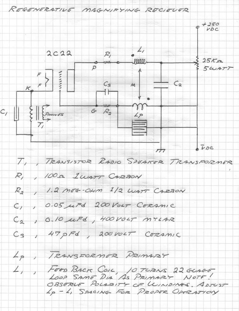
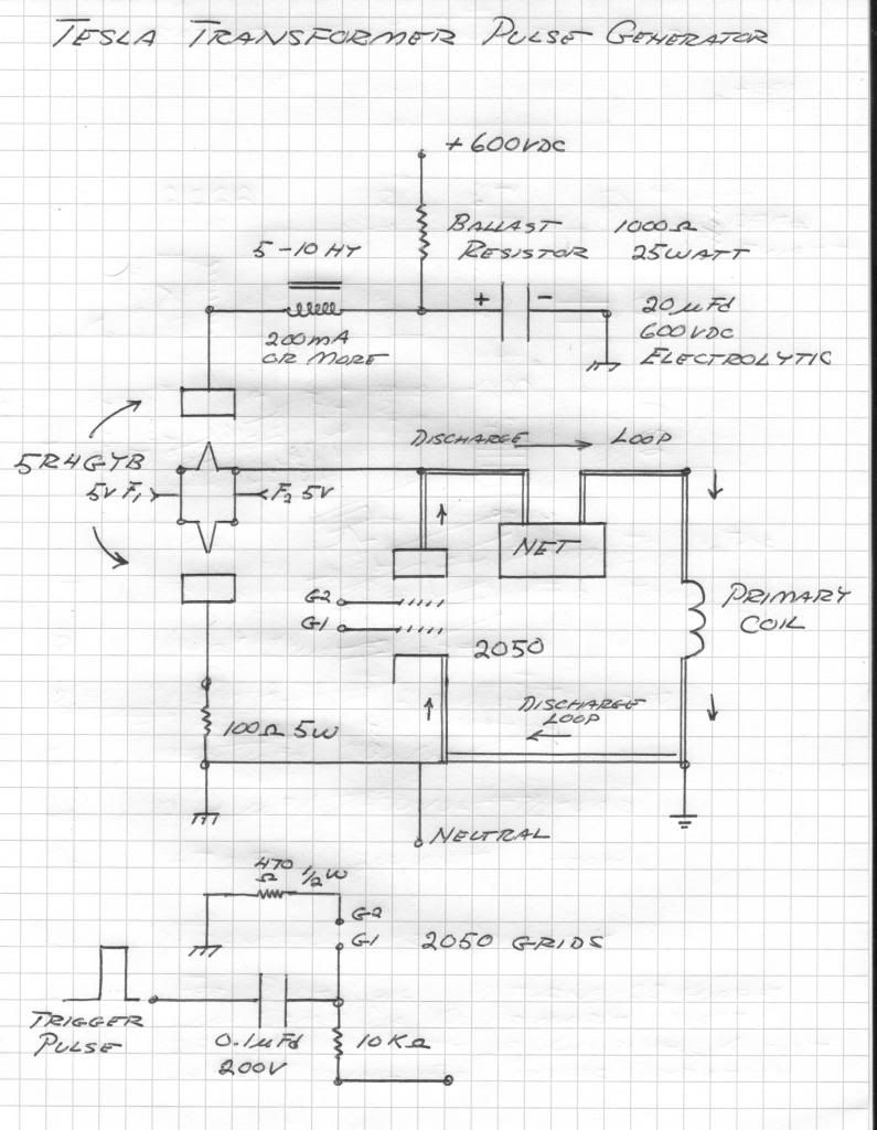
                    • Tentative Experimental Circuits, Use at your own risk!

                      Regenerative receiver is a 2C22 triode, and the pulse generator is a 2050 thyratron, and a 5R4GYB dual diode rectifier.


                      SUPPORT ERIC DOLLARD'S WORK AT EPD LABORATORIES, INC.

                      Purchase Eric Dollard's Books & Videos: Eric Dollard Books & Videos
                      Donate by Paypal: Donate to EPD Laboratories

                      Comment


                      • If the loading coil didn't contain any iron then none shall be used. I already have a selection of similar high current RF coils. A few of them are even variable, but about the size of a gallon jug. If there was additional inductance employed inside the disclosed 6 turn inductor (or other passive component) then, any information about its construction and/or connections would certainly help.
                        It was a small Alexanderson Coil, 40-50 turns in flat spirals. NOT a 6 turn inductor. It was a stack of flat spirals, with 6 layers, I have no idea what the inductance was, can't remember. It was wound on a porcelain block.

                        Even though I don't have a NE-34 I do have a IY-3 which is the same kind of lamp except filled with Aragon rather than Neon. Would you conjecture that Aragon could work as well as the Neon? I do have a lead on the NE-34. They were used in an early tube tester. I might have better luck chasing down the complete antique tube tester rather than the lamp by itself.
                        The neon bulbs aren't completely necessary, they just make it easier to see. Their just pilot lamps, indicator lights. Anything that glows really could be used, even fluorescents. Argon is difficult to see because it is ultraviolet

                        If hydrogen thyratrons can replace the 1B22's - then so much the better. I don't like using components that can't be found by other non-funded researchers. In your opinion can high speed-high voltage and high current SCR's be considered if the dv/dt response is similar? These offer power supply advantages and eliminate the need for special filament transformers. Plus they can be triggered by high speed logic.
                        NO SOLID STATE!

                        What is your opinion on the input storage 0.001 uF Mica Transmitter capacitor? I would like to use 10KV variable vacuum capacitors so that some fine tuning can be achieved. I have two 500 pF units that if wired in parallel would equal the same capacitance value. I do have some large Mica transmitter capacitors but my values are not exact. I have 0.0012, 0.00133, and 0.002 plus some other values.
                        Use vacuum capacitors instead of mica, they need to be adjustable in order to tune
                        SUPPORT ERIC DOLLARD'S WORK AT EPD LABORATORIES, INC.

                        Purchase Eric Dollard's Books & Videos: Eric Dollard Books & Videos
                        Donate by Paypal: Donate to EPD Laboratories

                        Comment


                        • Originally posted by Sputins View Post
                          T-Rex,
                          Why do you recommend the 2050 Argon Thyratron over others (5C22) for pulse experimentation? (The 5C22 is more expensive and less of them around).

                          Looking on the internet, the 2050 Thyratron is much more readily available and can be found at a reasonable price. (I have just bought myself a pair (RCA) for $42.00) Looks like the Cathode (heater) requires 6.3volts @ 0.6A, which isn’t too excessive & heavy.

                          If these tubes are generally affordable and plentiful enough, a common or universal circuit schematic could be developed for the “Electrical Experimenter” following these T-Rex transmissions, for use with similar devices. - The Anode supply required isn’t so high either, perhaps good for lower power systems to experiment and learn with, (although the 2050 is powerful enough). I am not very clued in on the gird supply circuit however. (Actually I have a limited (but growing) knowledge with tubes in general, – a common symptom for the today’s electrical experimenter). Perhaps this condition can be reversed.
                          The 2050 is cheap, safe, and you won't kill yourself playing around with it. It's only about 500 V. There is plenty of power to experiment with.

                          The 5C22 is extremely high voltage, very dangerous. Also it has stiff power supply requirements, by the time you were done building the supply you would no longer be able to lift the apparatus. Also harder to get, and expensive.

                          Originally posted by Sputins
                          In my case it happened with a small-ish capacitor of 0.5uF @ 2500volts, charged by a supply with a Logitudinal flux component from an L.M.D. set-up, rectified to DC and then finally discharged disruptively with the discharge "gap" being in the circuit after the main capacitor.

                          The Disruptive discharge resulting in a stinging shockwave on the first occasion was also done by accident.. I was just mucking around with the output of the of the charged capacitor, clamped one terminal to a heavily RUSTED metal grill, an the other terminal I held (insulated of course) and was rubbing it against the rust and metal on the grill. At some point while rubbing against the rust (which has a large dielectric constant) a spark punctured through the rust, and WHAM the shockwave, and sting was felt coming off the metal grill, through the air and against my arm and shoulder.

                          The rust being a strong insulator and pressing against it excluded the air, moving it gave me the pulse duration required. The first time it occoured was a complete fluke.. In fact only later did I realise what had occoured and possible reasons why.. (Thanks to Lindemann's work).

                          So now I am buliding a much more powerful version, with a mechanical (disruptive) switch utilizing Mercury and oil, (Hg & Glyserine actually, as it has a dielecrtic strength of 42). A W-rod will be operated in and out of the Mercury and glyserine with a high speed solinoid in a linear fashion. (Too hard a this stage to build a rotary one). Hopefully the switch will be fast and brief enough to "release" the Electro-static component.

                          I have already built the switch/gap but the first version exploded and broke the glass tube I contained it all in. (It went everywhere and lessons were learnt)! The next version will have to be made much more robust, say made of Teflon.
                          It may also work (I have not tried it) with (like the Gray tube) a combination of carbon (graphite) and silver? ..Another thing to try...?
                          Sputins,
                          Could you show any pictures, circuit schematics, etc. of the equipment you have built or are currently building? Or of the mercury switch?

                          [Note the following is not directed at you Sputins, it is for everyone contributing to this thread]

                          Eric wants to see pictures of things, schematics, specifications, diagrams. Not just words. He quickly grows bored of the forum with just talking, he likes to see actual equipment, so others can learn from what you're doing. What really gets him excited is people actually attempting to build stuff and experiment; then posting their results for others to see. It is important, as he is teaching us, we must also help teach others. Not every one knows how to build the equipment to experiment with disruptive discharges. This is how this problem of "secrecy" of Tesla technology came about in the first place, people not sharing information.

                          Quote from Eric: "I'm not going to hold your pecker while you pee, you guys are going to have to do some of this sh*t yourselves".

                          What he is referring to here is people doing the requisite background research to understand what he's talking about. Actually doing experiments and learning from them. Very little can be achieved by just reading the material he posts. Also you have to read the references he posts, to be able understand the material.

                          With me at least, he has given me some references to study to aid in building the CIG. I have to do the reading and understanding myself. To be clear, he is not holding my hand through this, I have to do the work and build it myself. So I have to do the reading, study, calculations, etc. He'll offer advice where needed. The same goes for this forum. Sort of like "the more stuff you put out, the more you get". This is how this thread can be more productive. I certainly plan on sharing as much as possible of my build, so others can see what I'm doing, maybe offer advice, or learn. I am pretty sure I know less than a lot of people here, and I'm sure I'll make some mistakes and show my lack of understanding in some areas, but I'm not concerned about that. I have very little practical electronics experience, but I'm diving in with both feet!
                          Please help support my indiegogo campaign: Cosmic Induction Generator

                          Comment


                          • I'm posting here as I would like Eric to see this and hopefully give some input. I'm wrestling with the displacement current model of Maxwell's modified Ampere law.

                            cutting to the heart of it, per the current equations it states that the E & B fields self propagate against each other in free space. The trouble is that using the equations to calculate the dielectric space of parallel capacitors and the resultant charge densities and magnetic flux, it gives extremely low values to what I'm actually measuring with my test setup. For example the maximum predicted charge in the field space is only 21.5volts, yet the 'loop' will show over 25volts. The predicted voltage for the loop is in the micro volts not equal to or greater than the free space charge.

                            The fringe effect is ignored, another big red flag that somethings not right.

                            The magnetic field may not exist as it's predicted value is no where near enough to induce the voltages measured. That then goes back to the E field being the primary driver, is it a time variant surface vector or instant?

                            I'm still digging through this and trying to figure how to resolve the miss match. It may not seem related here, but I think it is. If the electric charge between capacitance surfaces does not give rise to a magnetic field then this would support faster than C propagation in that axis provided the right constraints. What about capacitive reactance if the displaced current doesn't exist?

                            I also think this why aluminum and monoatomic hydrogen vapors paramagnetism is useful in plasma tubes.

                            Comment


                            • Originally posted by jpolakow View Post
                              The 2050 is cheap, safe, and you won't kill yourself playing around with it. It's only about 500 V. There is plenty of power to experiment with.

                              The 5C22 is extremely high voltage, very dangerous. Also it has stiff power supply requirements, by the time you were done building the supply you would no longer be able to lift the apparatus. Also harder to get, and expensive.


                              Sputins,
                              Could you show any pictures, circuit schematics, etc. of the equipment you have built or are currently building? Or of the mercury switch?

                              [Note the following is not directed at you Sputins, it is for everyone contributing to this thread]

                              Eric wants to see pictures of things, schematics, specifications, diagrams. Not just words. He quickly grows bored of the forum with just talking, he likes to see actual equipment, so others can learn from what you're doing. What really gets him excited is people actually attempting to build stuff and experiment; then posting their results for others to see. It is important, as he is teaching us, we must also help teach others. Not every one knows how to build the equipment to experiment with disruptive discharges. This is how this problem of "secrecy" of Tesla technology came about in the first place, people not sharing information.

                              Quote from Eric: "I'm not going to hold your pecker while you pee, you guys are going to have to do some of this sh*t yourselves".

                              What he is referring to here is people doing the requisite background research to understand what he's talking about. Actually doing experiments and learning from them. Very little can be achieved by just reading the material he posts. Also you have to read the references he posts, to be able understand the material.

                              With me at least, he has given me some references to study to aid in building the CIG. I have to do the reading and understanding myself. To be clear, he is not holding my hand through this, I have to do the work and build it myself. So I have to do the reading, study, calculations, etc. He'll offer advice where needed. The same goes for this forum. Sort of like "the more stuff you put out, the more you get". This is how this thread can be more productive. I certainly plan on sharing as much as possible of my build, so others can see what I'm doing, maybe offer advice, or learn. I am pretty sure I know less than a lot of people here, and I'm sure I'll make some mistakes and show my lack of understanding in some areas, but I'm not concerned about that. I have very little practical electronics experience, but I'm diving in with both feet!
                              Completely agree with Erics request and the sound reasoning behind it. look at it like lab time, first you research and calculate, then you get off your butt and 'work' get in the lab and put the book knowledge to the test, see where is fails and where it flies.

                              This is going to be a time consuming venture, those going down this road need to accept that it'll take time and work. I've personally done yrs of R&D in the field and lab before desired results are obtained.

                              At the moment I'm still acquiring the 'parts', doing other related research and trying to run a business. there seems to be a shortage of time, I say lets move to mars and take advantage of the longer days

                              One question, in today's highly regulated world is the current draw on the utilities going to be an issue with these setups?

                              Comment


                              • 2C22 tube data


                                SUPPORT ERIC DOLLARD'S WORK AT EPD LABORATORIES, INC.

                                Purchase Eric Dollard's Books & Videos: Eric Dollard Books & Videos
                                Donate by Paypal: Donate to EPD Laboratories

                                Comment

                                Working...
                                X