Announcement

Collapse
No announcement yet.

Eric P. Dollard

Collapse
This topic is closed.
X
This is a sticky topic.
X
X
 
  • Filter
  • Time
  • Show
Clear All
new posts

  • # 3 Extra Coil

    Have been out of action for 2 weeks due to a small operation on my hand/arm but now back in business.

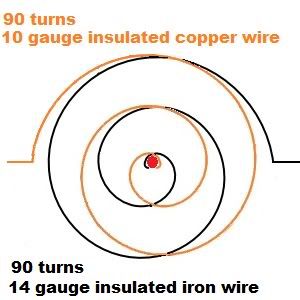
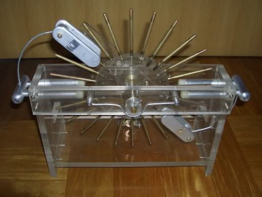
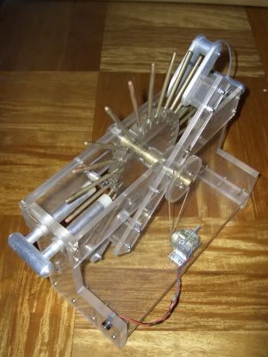
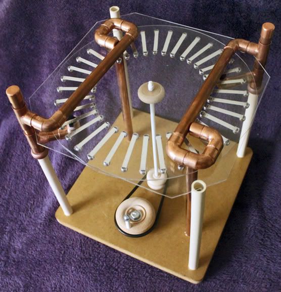
    Have finished the 3rd Extra Coil as seen below, first on LHS is my 'accidental' which worked using the CSN data that showed the Secondary and Extra to be of nearly equal length, mid is using Eric's Math which didn't work and the 3rd is the extended using 11 awg vice 14 awg as used on the first.
    Have just finished comparing the 3 with the NO COIL aerial I accidently discovered yesterday that you don't need a coil, just an Antenna and a good full wave 1N34 pickup head for the Headphones.
    Listening today just on the wire appeared to be slightly louder.
    I tried with the variable condenser in the circuit but better without.

    # 1 coil was good with signal loud and clear, level 5
    # 2 was barely audible and below level 1
    # 3 about same as #1 possibly slightly better
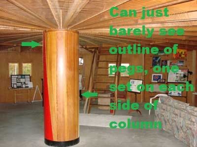
    An alligator clip wire of about 1' length just attached to the top of the Extra improved level slightly and a hand around that another slight improvement.
    The new Extra has 56 turns where calculations show 50 as best so may have to do some tuning here.
    Much work still to be done in this area.

    The Oscilloscope picture is a comparison between 'Crystal Set' and a nearby Radio but I am unable to detect any difference from that shot and others taken were the same.
    Signal was pure audio either voice or music.
    A need to review and will use the Tektronix 564B Tube Osc as that above was from the HP1741A.

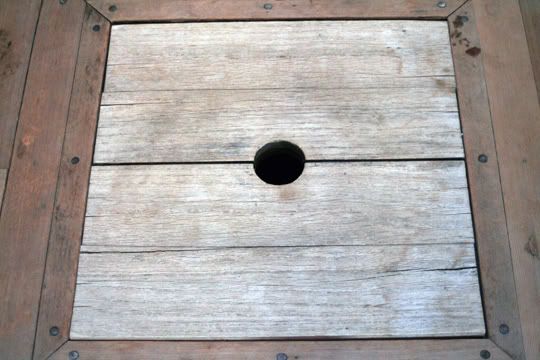
    Also added a better closeup of the pickup head as I now know how to do closeups with my Canon camera.

    Going to do a test on my infinite fencing I have here and see what level I can produce and this will be on all the metal I can find, house rooves, tin sheds, cars, TV antenna, Grounds, Trees etc etc.
    We need to know a lot more about our surrondings and what is really going on.

    Smokey
    Attached Files

    Comment


    • Originally posted by jpolakow View Post
      For this you will need a voltmeter, and a 0-500 Ohm resistor (rheostat). Put the voltmeter on the test oscillator and adjust the output of the oscillator until it reads 100% scale on the voltmeter. Now put the variable resistor across the output of the oscillator, with the voltmeter connected to it as well. Now adjust the resistance of the rheostat until the voltmeter reads 50% of what it was initially. Disconnect the variable resistor and measure the resistance of its setting. That is the output impedance of the oscillator. Now the voltage is divided evenly between the internal and external impedance. This is how you measure the impedance of any source of alternating or direct current.
      Very good, thanks for the info
      http://www.teslascientific.com/

      "Knowledge is cosmic. It does not evolve or unfold in man. Man unfolds to an awareness of it. He gradually discovers it." - Walter Russell

      "Once men died for Truth, but now Truth dies at the hands of men." - Manly P. Hall

      Comment


      • First set of extra coil test results: Frequency Vs Capacitance

        Extra coil calculations used

        http://i168.photobucket.com/albums/u...ensions001.jpg

        For 20 turn secondary F = 3670000 cycles/sec

        Height = 8.28cm
        Diameter = 8.28cm
        Number of turns = 126
        Wire = 32.27 metres 26 SWG

        Beer can distance from extra coil = 23cm

        Setup


        Capacitance measured =

        0pF (metallic connection)
        5pF
        10pF
        25pF
        50pF


        Relative extra coil readings from a constant signal generator output level (first test carried out - prior to increasing signal level and finer tuning for capacitance vs frequency test):

        Signal generator output =
        Vrms 2.458V
        Vpeak/peak 7.12V


        More later.
        Last edited by dR-Green; 06-14-2012, 10:08 AM.
        http://www.teslascientific.com/

        "Knowledge is cosmic. It does not evolve or unfold in man. Man unfolds to an awareness of it. He gradually discovers it." - Walter Russell

        "Once men died for Truth, but now Truth dies at the hands of men." - Manly P. Hall

        Comment


        • Vesica Pisces

          Was actually looking for a Tube Amplifier and came up on this to do with the Vesica Pisces ('Heart Of God') and there are those words again 'synthesis' and 'Golden proportion' meaning the 3 Roots of 2, 3, and 5 - see below:

          Now get this in basic Math form:
          Root 2 =1.414
          pi/2 = 1.571
          Root 3 = 1.732

          Why pi/2 in the middle? - because that's pretty much exactly where it sits!
          0.157 and 0.161 difference, another accident or telling us something?
          So add Root 2 and 3 and you have pi.

          See those words 'dividing' and 'transforming', 'duality' and confusion'.
          So what happens now when you pump a coil form in the Root ratios, something manifest out of nowhere, like energy, how about a vision or an Alien from another dimension?
          The attachment is from a book by Robert Lawlor called 'Sacred Geometry'.
          Still working where Root 5 fits in.
          Anybody?

          Smokey
          Attached Files

          Comment


          • Dr. Green #677

            1) Secondary Coil Luminal Velocity Frequency
            5.77 Mc/sec

            2) Meter and Can Frequency
            3.47 Mc/sec

            3) Percent Luminal Velocity Effective
            60 %

            4) Conclusion is that meter can has too much capacity

            Dr. Green #677 (II)

            1) Secondary Coil Luminal Velocity Frequency
            5.77 Mc/sec

            2) Ring and Meter-Can Frequency
            4.04 Mc/sec

            3) Percent Luminal Velocity Effective
            70 %

            4) Conclusion, bring rings closer together

            Dr. Green #677 (III)

            The meter and can you are using is too big, to much capacity for direct connection at the higher frequency of operation. The one given is a broadcast frequency much lower (larger). Use your meter only with the can as a pickup. The tuning condenser is the ring spacing. Connect upper ring to coil neutral solidly. Face meter can probe to side of upper coil portion for measurement. Adjust ring spacing for proper frequency.

            Dr. Green #677 (IV)

            The wire used on the coil is not right. It must be teflon insulated for wood rods. Also about 16 gauge is as small as one should go on wire size. The earth connection to neutral connection cannot be wires, sheets of metal and a ground plane at least 3 times coil diameter under coil with coil about 2 feet above it. Also, oscillator coupling must be the absolute minimum. With these considerations the tuning curve will be much sharper and the magnification much larger.

            Dr. Green #690 (I)

            1) Extra Coil Luminal Velocity
            2.31 Mc/sec

            2) Extra Coil Maximum Velocity Frequency
            2.85 Mc/sec

            3) Percent Operating Velocity to Luminal Velocity
            123 Percent

            4) Velocity can be raised by smaller input capacity

            Dr. Green #690 (II)

            Coil wire must be teflon insulated. Wire gauge about 20 gauge minimum. The absolute minimum of insulating support is essential. Plexiglass rods best.

            Note, zero capacitance is an open circuit, NOT a direct connection. Your graph should be a hyperbolic curve, NO sharp inflections. It is based on Epsilon to the square root of CK power.

            D. Dawson (I)

            The equations I have provided are for ball park use. The secondary is developed for a ring condenser tuning to the operating frequency. Also remember that not only one resonance exists, but there are an infinite number of them. Experimental results are my objective here, Dr Green and Geometric Algebra have carried this out.

            D. Dawson (II)

            It is important to remember that Tesla's extra coil at Colorado Springs was heavily loaded bringing the wire length down considerably. Two loads, or burdens, existed. One, with a 135 foot capacity mast on the high side of the extra coil. Two with a large series inductance in the neutral lead of the extra coil. This inductance takes the place of the mast when it is not used. For the utilization here on the forum the aim is to have the complete quarter wave in the extra coil.

            General; The connection of the secondary to the extra coil directly gives rise to a current minimum directly at that connection, not in either coil. This is almost impossible to derive analytically. We are doing it experimentally. I recently gave the correcting equations for the "Theory of Wireless Power" formulae on coil design. Someone should finish this and then calculate the impedance and frequency for their own coils. Once this is done then everything is a basic transmission line problem.

            73 DE N6KPH
            SUPPORT ERIC DOLLARD'S WORK AT EPD LABORATORIES, INC.

            Purchase Eric Dollard's Books & Videos: Eric Dollard Books & Videos
            Donate by Paypal: Donate to EPD Laboratories

            Comment


            • Thanks for the tips. I understand a lot more now after that explanation and actually doing the tests. There are a lot of variables that have obvious effects so I didn't know where to start. The ground plane is 60x60cm piece of tinfoil sandwiched between cardboard, I'll put that under the desk and make some changes and do the tests again. The only immediate fix I can think of for the earth connections is to use strips of aluminium tape.

              Originally posted by T-rex View Post
              Wire gauge about 20 gauge minimum.

              Note, zero capacitance is an open circuit, NOT a direct connection. Your graph should be a hyperbolic curve, NO sharp inflections. It is based on Epsilon to the square root of CK power.
              I thought the secondary and extra coil wires had to be the same gauge? As for zero capacitance, I had to call the direct connection "0" for the computer to understand it. I'll remove the direct connection from the graph and try other capacitor values in between the ones already measured.

              I already did the extra coil frequency sweeps with the given capacitances last night so I'll post those next.
              http://www.teslascientific.com/

              "Knowledge is cosmic. It does not evolve or unfold in man. Man unfolds to an awareness of it. He gradually discovers it." - Walter Russell

              "Once men died for Truth, but now Truth dies at the hands of men." - Manly P. Hall

              Comment


              • Just making some improvements before doing all the extra coil tests again and wanted to make note of some changes/observations before drastic differences in results come up. I previously had about 10cm of lead-out wire on the top end of the extra coil, which was positioned not to be extending towards the can, but also not being too close to the top of the coil as an extra turn. Well this little piece of wire obviously has a big effect. Extending it out towards the can, the peak frequency dropped from 2.84 Mc to about 2.79 Mc. So I cut some of it off, and then some more. About 1.4cm of wire cut off brought the frequency up by about 15-20 kc. 7.4cm of lead-out wire was removed in total and the peak frequency is now around 2.88 Mc (about to fine tune it and take measurements).
                http://www.teslascientific.com/

                "Knowledge is cosmic. It does not evolve or unfold in man. Man unfolds to an awareness of it. He gradually discovers it." - Walter Russell

                "Once men died for Truth, but now Truth dies at the hands of men." - Manly P. Hall

                Comment


                • Crystal Set Iniative/Fence Aerial

                  Eric,
                  Thankyou for the information.

                  All my results are at 'n6kph' but will redo on all 3 Extra Coils as a comparison and also the Secondary test.
                  Will also add documents here as attachmnents and not as Thumbnails.

                  Will also raise my setup at least 2' above the Ground plane and note any differences.

                  Not sure I understand what you are saying with respect the Extra Coil but will review after tests.

                  Fence Aerial experiments half done with surprising results considering NO Coil used.
                  Now looking for a metal Water main outlet for comparison.
                  Coils would give you bandpass where more than one AM Station would be heard.
                  Funny that nobody in all my research has done what I am now doing without Coils.
                  One area of fence was so loud that I am tempted to put a speaker onto that point.

                  Smokey

                  Comment


                  • After 8 hours or so of work, I've made some changes and did the extra coil tests again. As mentioned above 7.4cm of lead-out wire was removed from the top end of the coil. Beer can distance from extra coil is increased to 28cm. Extra coil raised to 52cm above ground plane. Additional 2.5pF capacitance measured.


                    New frequency response with metallic connection


                    Frequency response with different capacitors (charting not possible with 2.5pF and 28cm beer can distance - meter range too high):


                    New frequency vs capacitance graph


                    Given

                    Originally posted by T-rex View Post
                    1) Extra Coil Luminal Velocity
                    2.31 Mc/sec
                    2) Extra Coil Maximum Velocity Frequency
                    2.922 Mc/sec

                    3) Percent Operating Velocity to Luminal Velocity
                    126 Percent
                    http://www.teslascientific.com/

                    "Knowledge is cosmic. It does not evolve or unfold in man. Man unfolds to an awareness of it. He gradually discovers it." - Walter Russell

                    "Once men died for Truth, but now Truth dies at the hands of men." - Manly P. Hall

                    Comment


                    • Dr. Green #396 (I)

                      Consideration of Coil Self Capacitance
                      1) Extra Coil Diameter
                      8.25 cm

                      2) Capacitance factor from Radiotron table for a coil aspect ratio of 100%
                      .46 Numeric

                      3) Multiply this by the coil diameter
                      3.8 picofarads

                      4) This is the "free space" self capacitance of this extra coil. This means a true air wound coil.

                      Now to determine the actual working capacitance of this extra coil resulting from the coil form and stray lead parasitic capacitance.

                      1) The theoretical velocity factor from the Wireless Power Table for a coil with a 100% aspect ratio:
                      187% numeric

                      2) The actual measured velocity factor
                      124% numeric

                      3) Taking the ratio of the free space to actual measured velocity gives
                      1.51 numeric

                      Note, close to 1.54, pi/2

                      4) Velocity varies as the inverse of the square root of the capacitance
                      2.28 numeric

                      5) Multiplication of the free space capacitance by this squared factor
                      8.7 picofarads

                      6) This is the burdened coil capacitance resulting from the coil form and connecting leads.

                      Observe that the 45 degree knee or asymptote point is this derived value of capacitance. This effective coil capacitance is the square root of its self capacitance, C and its mutual elastance, K.

                      Dr Green #396 (II)

                      Considerations of the magnification factor as derived from the bandwidth of the resonance curve, this the half power, or 71% voltage points on the curve.

                      1) Determine the 71% points on the extra coil curve (for 10 pFd).

                      Lower Sideband Point
                      2821 Kilocycles/sec

                      Upper Sideband Point
                      2831 Kilocycles/sec

                      Hence the half power bandpass is 17 Kilocycles or 6%

                      2) Two factors are here derived. Factor d is the ratio of the bandwidth to the center frequency, 2830 Kc/sec.
                      0.006

                      Factor n is the inverse of factor d:
                      167

                      3) Here derived is the magnification factor of this extra coil,
                      n = 167 numeric

                      General Conclusions

                      This extra coil is now quantified as to its general electrical behavior:

                      v = 124% luminal velocity
                      C = 8.7 pico
                      Farad
                      n = x 167 magnification factor

                      73 DE N6KPH
                      SUPPORT ERIC DOLLARD'S WORK AT EPD LABORATORIES, INC.

                      Purchase Eric Dollard's Books & Videos: Eric Dollard Books & Videos
                      Donate by Paypal: Donate to EPD Laboratories

                      Comment


                      • Dr Green Extra Coil

                        The inductance, characteristic impedance and resonant frequency of this extra coil is now developed.

                        1) The magnetic inductance of the extra coil by Wheeler's formula (Theory of Wireless Power) is
                        846 microHenry

                        2) The effective inductance for a cosine quarter wavelength current distribution is

                        by Steinmetz, two over Pi the total inductance,
                        539 microHenry

                        By Miller, one half the total inductance,
                        423 microHenry

                        3) The equivalent capacitance of the extra coil is given as
                        8.7 picoFarad

                        4) The effective capacitance for a sine quarter wave distribution is

                        by Steinmetz, two over Pi times C,
                        5.5 picoFarads

                        by Miller, eight over Pi squared times C,
                        7.1 picoFarads

                        4)The Characteristic coil impedance is defined as the square root of the ratio of inductance to capacitance

                        By Steinmetz
                        9.9 Kilo Ohm

                        by Miller
                        7.7 Kilo Ohm

                        5) The angular frequency is defined as the inverse of the square root of the product of inductance and capacitance

                        18 Kilo-radians per second
                        or
                        2860 Kilocycles/sec

                        This concludes the calculation of the important characteristics of the extra coil under study

                        73 DE N6KPH
                        SUPPORT ERIC DOLLARD'S WORK AT EPD LABORATORIES, INC.

                        Purchase Eric Dollard's Books & Videos: Eric Dollard Books & Videos
                        Donate by Paypal: Donate to EPD Laboratories

                        Comment


                        • More Info on the Original Integratron (Part 1)

                          Here are some original construction photos of the Integratron. It was built using all wood, no metal. To fasten the boards together pegs were used.


                          George Van Tassel was the originator of the Integratron. He claimed to have contact with space beings (Venusians) who gave him the blueprints for the device. George Van Tassel:


                          Bird's eye view of the dome:

                          Interestingly enough it looks similar to a flying saucer from the top.

                          A model picture of the dome:


                          Note the protruding pegs projecting from the sides of the model. Also note the small silver globes. Viewed on the Integratron:


                          The protruding pegs are made of aluminum, the frame to which they attach is a rotor, it spins around the dome. The rotor spins supported by teflon bearings. The rotor forms an electrostatic armature, with each aluminum peg being a small capacitor. It is a dirod generator. The armature rotates, building up an electrostatic charge. The charge collects on the silver domes, building up in magnitude. Brushes hang down from the charge collectors, touching the aluminum posts, to collect charge off the aluminum.


                          An enormous electrostatic charge would build up on the collectors, around 1,000,000 (one million) Volts. So a safety spark gap was added if the voltage got too high. There were 4 charge collectors, equally spaced around the diameter of the armature. I've superimposed them in the following picture:

                          The 4 separate charge collectors make it a Four Quadrant Device. This info is contained in George Van Tassel's many books.

                          The 4 charge collectors now have a large voltage stored on them. The energy is to be used inside the Integratron in two places. To switch the energy spark gaps were to be made next to the charge collectors. I edited into the picture an extra set of globes. Note: how they are displayed here are just speculation, they could have been made out of a different geometry or placed differently, the following is just for illustrative purposes:


                          The spark gaps did not do the actual switching. They are just there to transfer the charge. The actual switching was done by air driven switches. Pipes of compressed air were run to the switches, then the switching was controlled inside the dome. There is a central air compressor stored in a shack outside the dome, which provides the air supply. (Note bird's eye view picture). Also note that contained within this shack was a Marx Generator, to do tests with the high voltage electrostatic charge without having to actually turn the armature.

                          Also the compressed air provides the motive force to turn the armature, so the speed of the rotor can be controlled, as well as the switching of the charge collectors. The actual designed operating speed of the armature is unknown, Eric was planning on turning the armature with a horse pulling the wheel with a nylon rope attached. The 4 charge collectors power two things: the dome of the Integratron, and the Caduceus coils located on the ceiling of the downstairs.

                          A view of the downstairs:


                          Please help support my indiegogo campaign: Cosmic Induction Generator

                          Comment


                          • Integratron Part 2

                            Coil on ceiling of downstairs:

                            Note: this is not the original coil done by Eric. Any evidence of what Van Tassel or Eric did was removed. The original coil was torn down by the current tenants and replaced with this "thing". A classic example of what not to do- have bare copper wire touching wood. Also this is not a Caduceus, more on that later. If you look closely you can see pegs protruding from the left side of the central column. These were coil forms:


                            There are two such forms, one on each side of the column, one painted white and the other painted red:


                            The pegs were supposed to provide a coil form for copper wire to zig-zag across, forming a a capacitive triangle:


                            So there would be two zig-zag coils, one on each side of the central column. The coils were intended to capacitively-couple with something on the inside of the column. What that was supposed to be is unknown to Eric, Daniel Boone was responsible for that. It possibly could have been something made of Iron. Here is a trapdoor in the upstairs of the Integratron, that leads down to the center of the column:


                            On the ceiling of the downstairs, where the current bare copper wire coil sits, was originally a Caduceus coil. It was actually originally two counter-wound Caduceus coils, one made of copper, and one made of Iron. They were wound around pegs, 90 turns for each coil. The outside diameter for each coil was around 40-50 ft. The wires were both insulated:

                            The center of each Caduceus was attached to one of the zig-zag coils on the central column, as displayed by the red circle in the diagram above.

                            The Caduceus coils were then connected to opposite charge collectors on the armature.

                            The ceiling of the Integratron was to be coated with Aluminum Foil, to form a capacitance between the dome and the earth's ionosphere. One plate of the condenser is the dome, the other is the earth's ionosphere. Aluminum foil was to be glued to the wooden ceiling as depicted in the model below:


                            The ceiling was then to be connected to the other two opposite charge collectors on the armature. Also, the ceiling was divided into 16 distinct sections, 22.5 degrees apart:


                            The ceiling was to be covered in foil, it could have been covered all as one contiguous condenser plate, or the 16 sections could have been isolated electrically, and each section forming a separate capacitance. Shown is part of the ceiling shaded in to display the concept:

                            Ultimately how it was to be configured is unknown, however if they were isolated electrically, and then charged separately from the charge collectors, there would likely be arcing over at the center of the ceiling where all the sections meet in close vicinity.

                            The safety gap shown earlier was to prevent the dome's electrostatic charge from becoming too high.

                            What is interesting is that the dome of the Integratron and the dome at Wardenclyffe share an uncanny mushroom shape resemblance:


                            Nobody is too sure what Tesla was up to at Wardenclyffe, for all we know he could have charged the Wardenclyffe tower dome up to a high DC potential, however this is just speculation.
                            Last edited by jpolakow; 06-16-2012, 03:08 AM.
                            Please help support my indiegogo campaign: Cosmic Induction Generator

                            Comment


                            • Additional info on the Dirod Generator:
                              Here are some pictures of Dirod Generators:


                              This one is probably the closest to the Integratron, but with 2 poles instead of four:


                              In this one you can see the arc at the top:


                              Dirods are an interesting type of electrostatic generator, they are unlike Wimhurst machines in that they don't need two counter rotating disks. They are a kind of motional capacitor, similar to the Chris Carson rotary condenser machine. The Dirod Generator is basically a parameter variation device.

                              Where a classic Electromagnetic generator works by cutting lines of force,
                              Dirod generator works by stretching the lines of force, tearing them apart. Ultimately electrostatic generators are difficult if not impossible to understand because people don't understand the Dielectric Field.

                              NOTE: Eric spent considerable time and effort helping me put this article together. His funds are running low, he survives only through the donations of others. A reminder that if you are interested in continuing to read his writings, he needs your continued support.
                              Please help support my indiegogo campaign: Cosmic Induction Generator

                              Comment


                              • Integratron

                                Eric, John,
                                Thankyou for that, especially the Dirod Electrostatic Generator.

                                OK, so no bare Copper onto wood which is what my latest Extra is doing as wire is not insulated.
                                Every second dowel has a sticky two sided tape onto the dowel to maintain gap integrity.
                                Will place an insulator under the other four and see what difference it can make.

                                Integratron:
                                What did the original ceiling coil look like and what was wound around the central post and could we assume this to be similar to a Lakhovsky type device?
                                Ceiling coil more like your Log Periodic or Lakhovsky MWO?
                                Electrostatic field from the Cyclotron/Dirod Generator into the Aluminium roofing of the dome and a Lakhovsky multi wave from the floor or first floor ceiling and the central post a Lakhovsky/Tesla Primary?

                                My schematic from what I have been able to gather from the facts given from previous research.

                                What would the Cyclotron rpm be - assuming at Earth Resonance?
                                Think I gave this as 405 Hz base.

                                Thanks.

                                Smokey

                                Comment

                                Working...
                                X