Announcement

Collapse
No announcement yet.

Eric P. Dollard

Collapse
This topic is closed.
X
This is a sticky topic.
X
X
 
  • Filter
  • Time
  • Show
Clear All
new posts

  • Originally posted by David G Dawson View Post
    Adam,
    Quote:

    "Eric/David I have a transformer I am building that has an outside metal around the coil and an inside metal core in coil. Think about that, and the ratio that would exist if the outer core were attached to the inner core, and how it would effect the propagation of electricity."

    Think we may have a common 'Oscillatory Chamber' here in mind.
    Going to have to read what you have presented but getting the gist of what it is all about.
    Thankyou for your support.

    Not an easy task getting a 'something' different through to people who think they have heard it and know it all.
    Newcomers are excused as you have come here to learn and you may just have a slight inkling that 'something' new has been discovered here.

    The only way you are going to see what I am seeing is to build using my theory of 'MUltiply' and not Eric's 'Divide'.
    All the information is now also clearly displayed here as well as at 'n6kph'.

    DrGreen, my apologies and yes all 3 coils are close to 300pF and this is for Eric's Test# 1 of the Extra Coil.

    Going to try to get some full size pics organised.

    Smokey
    Smokey,

    Please don't feel as if your work is not getting any attention. Everything you have posted has been viewed and stored and helped me. You and Eric are on a different "wavelengths" and this is to be expected in a field that is as Eric put it "un-charted territory".

    It seems that you know what you are doing and if not for your coils we may not have the calculation examples that Eric has presented. It does not matter to me that you have a different opinion then Eric. It actually has helped the process because your results have lead the the previous post. I now know(kinda of, think so) what to expect and how Eric expects to achieve it. Now just because you have been unable to make the longer extra coil work does not mean it is not correct.

    You are choosing a different path. I look forward to seeing you results and what you can do with them. Like I tell my good friend who has been working on Stan Myers water fuel cell for years....

    "MAKE IT WORK, then tell me how you did it"


    In the end it comes down to what you want to achieve from all the work you are doing.

    Everyone here wants to achieve something different.

    I want to: Light a damn bulb with a copper wire, and a good ground.


    jake

    Comment


    • Originally posted by T-rex View Post
      It must be remembered that this effort is really for the experienced transmission engineer, not the HAM operator, and surely not for the beginner.
      Thank you Eric. I'm definitely a beginner, not even a HAM operator, but I'm up for the challenge I'm not up to date on all the theory which is why I don't participate in much discussion on that side, but I learn faster by doing the practical first.

      Anyway, my signal generator is 5 Mc maximum so I can't look up there for any resonant peaks until I get the non-oscillating AVO fixed. I can take turns off the extra coil and spread out what's left so it's still 1:1 ratio. The remaining wire length should then be straight forward enough to do something with.

      But I wonder where to go from there... Make a new extra coil using the new found wire length to get back to 126 turns on a smaller frame? Or keep it on the existing frame with less turns.
      http://www.teslascientific.com/

      "Knowledge is cosmic. It does not evolve or unfold in man. Man unfolds to an awareness of it. He gradually discovers it." - Walter Russell

      "Once men died for Truth, but now Truth dies at the hands of men." - Manly P. Hall

      Comment


      • Originally posted by David G Dawson View Post
        Not going to agree with you that the Secondary is the Telluric magnifier here as my method clearly displays a 'something' else.
        In my opinion it's pretty much confirmed, because a flat spiral works as a Telluric receiver, consisting of only a primary and secondary coil. So it would seem that the frequency is set in the secondary. I made a flat spiral before coil equations were posted, it has about 52 metres of wire in the secondary. For the same radio station frequency, Eric's coil calculation gives me 54 metres secondary. The flat spiral is therefore easy to get working as a crystal radio for the same frequency with some capacitance across the secondary. There's no extra coil in this setup at all.

        The limitation I've come into with this is not being able to get beyond a certain voltage in the primary, which in my opinion could be due to a lack of extra coil, or poor grounding (most likely I think), or details in the coil construction, or a combination of all these. I can't confirm this part until I upgrade the grounding to begin with because I think that's the main problem.
        Last edited by dR-Green; 06-27-2012, 09:22 PM.
        http://www.teslascientific.com/

        "Knowledge is cosmic. It does not evolve or unfold in man. Man unfolds to an awareness of it. He gradually discovers it." - Walter Russell

        "Once men died for Truth, but now Truth dies at the hands of men." - Manly P. Hall

        Comment


        • Originally posted by dR-Green View Post
          In my opinion it's pretty much confirmed, because a flat spiral works as a Telluric receiver, consisting of only a primary and secondary coil. So it would seem that the frequency is set in the secondary. I made a flat spiral before coil equations were posted, it has about 52 metres of wire in the secondary. For the same radio station frequency, Eric's coil calculation gives me 54 metres secondary. The flat spiral is therefore easy to get working as a crystal radio for the same frequency with some capacitance across the secondary. There's no extra coil in this setup at all.

          The limitation I've come into with this is not being able to get beyond a certain voltage in the primary, which in my opinion could be due to a lack of extra coil, or poor grounding (most likely I think), or details in the coil construction, or a combination of all these. I can't confirm this part until I upgrade the grounding to begin with because I think that's the main problem.
          The mutual Inductance of the secondary should cause a negative resistance on the primary coil, thereby causing what Steinmetz described as a cumulative oscillation.

          Theoretically this accumulation in voltage in the T.M.T itself is asymptotic as Eric describes except for when the load is greater than the power recirculation ratio per second-. Check Primary & Secondary Coils. I believe this has the Steinmetz descriptions in it. They were very helpful to me in understanding some of the basics.

          Both Dollard and Steinmetz give 3 configurations, where the load is equal to the accumulation per second. Where the load is greater per second, and when the accumulation is greater than the load. This gives 3 distinct modes of operation. Energy storage over time. Energy discharge over time, and Energy equilibrium over time. I believe that the mutual inductance of the secondary coil to the primary via reverse resistance (-i) is inhibited without the presence of an extra coil. However I am an amateur/beginner as Eric describes, so perhaps he will have something to say about it.


          Best,
          A
          Last edited by 7redorbs; 06-27-2012, 10:08 PM.

          Comment


          • Originally posted by David G Dawson View Post
            Adam,
            Quote:

            "Eric/David I have a transformer I am building that has an outside metal around the coil and an inside metal core in coil. Think about that, and the ratio that would exist if the outer core were attached to the inner core, and how it would effect the propagation of electricity."

            Think we may have a common 'Oscillatory Chamber' here in mind.
            Going to have to read what you have presented but getting the gist of what it is all about.
            Thankyou for your support.

            Not an easy task getting a 'something' different through to people who think they have heard it and know it all.
            Newcomers are excused as you have come here to learn and you may just have a slight inkling that 'something' new has been discovered here.

            The only way you are going to see what I am seeing is to build using my theory of 'MUltiply' and not Eric's 'Divide'.
            All the information is now also clearly displayed here as well as at 'n6kph'.

            DrGreen, my apologies and yes all 3 coils are close to 300pF and this is for Eric's Test# 1 of the Extra Coil.

            Going to try to get some full size pics organised.

            Smokey
            I am unsure whether in all dimensions it is true to say that a division of current cannot create an amplification. Leedskalnin speaks imperatively about both dividing and concentrating magnetic current. I wonder what he specifically meant by that. Much in the examples of power lines by Eric, whereby the lack of grounding causes a "growth" for quite some period of time, I believe until the power station itself "goes kapoot-bang". I associate this with a "runaway" chemical reaction. In this case instead of acid and metals in battery annode and cathode we have a plasma that has a similar current flow established, and an increase in voltage that could be associated with the orbiting "electrons" or magnets of mass.

            I believe that the ultimate coil, particularly in reference to your comments and mine about transformers with inner cores and an "outer core" around the winding itself, is essentially a vast representation and recreation of the atomic orbit, whether it is an electron or two magnetic fields of magnetic and dielectric proportion becomes mute. Rather that magnetic fields of the north and south "lines of force" type, are propagating in two directions, Forwards and backwards, as well as around in a vortex like right hand twist fashion. The transformer then by inductive observation might be described as an accelerator, or rather a channel of matching geometry for a moving and spinning field of north and south pole kind. In short, the coil mimics the rotational field of a bar magnet north and south pole.

            In the case of the tentative coil dimensions given by Eric I believe there is an intention to create a bias in one of the poles. However I could be mistaken. Eric's work is so much more complicated than mine.

            In the case of Edward Leedskalnins flywheel and Nikola Teslas Wardenclyffe I do believe the goal is quite clear, to mimic the chemical orbits that we find in a battery, or rather to stretch and extend the perfect geometric orbit of the magnetic current (and corresponding field at 90 degree's to it's flow). Making the Tesla coil or Leedskalnins wheel a complex number representation of flowing current of approximate rotational complexity to that of an atom.

            If the replication of the atom is scaled up perfectly in this way. The minute amount of energy that is available from individual chemical atoms orbit rotation is very very small. It is energy though. Tesla points this out to us in his "wheelwork of nature". He says energy will eventually be derived at any point in the universe, and that some adaptation of this system he claimed to have conceived can transmit "regardless of distance". I would point the electrical engineer and scientific researcher to the wonderful Theory of Quantum Electrodynamics (cough cough) which points out that one atom's particles can be quite entangled with constituent parts of another. It would appear that a chemical knowledge would go a long way in understanding the fundamental functioning of entangled so-called "electrons", or rather, what base that is smaller might exist beneath them. Indeed - this would dictate the geometry and the mathematical dimensions of current that would dictate our best energy storage devices.

            Tesla says that the energy system between the sun and the earth is a superior energy storage system. After all if it wasn't it would not be able to support the life on the earth. It may be that much of the excitation of periodic elements itself is caused by the rays of the sun, not enough exploring has been done by electrical engineers into the realms of space, and it is difficult to comment without experience.

            I cannot emphasise enough the importance of the chemical energy factor that Steinmetz hinted on. It has not been looked into enough. If all energy generation is involved with the breakdown of periodic elements matter, and the loss of their layers of so-called electrons.

            Regarding the work with elevated terminal and capacitance, I have noted that North and South pole individual lines of force are of equal strength on a level ground. Which is why I still am not sure about these "electron things". I struggle to keep up with some of the terminology used by engineers, and remain convinced that a natural-system of observing the nature of the electrical sub-atomic perpetual orbit current systems may reveal a way for us to setup identical ones chemically, of much larger scale - like that of the mass of the earth itself. It appears that Tesla had this in mind. I suspect that using a magnetic field propagating into the ground is the cause of the longitudinal wave. Earthquakes for instance might provide revealing information about the angular momentum of the rays from the sun and the longitudinal shifts and secondary sound waves produced from the land masses in quakes.

            It appears the T.M.T's magnification is that of decibels, or amplification of effective "sound". Could we assume that a purely mechanical system could be devised that of a piano playing notes on a string at high speed? I had an idea for a transformer whereby the oscillating movement from an electromagnet spark gap could vary the tension and distance of the entire transformer through a spring - this would be a self referencing differential, whereby the input current's impulse timing, effects the variation timing by delay. I am essentially trying to find a way to smack a string (musical note or organ pipe) incrementally faster in a mechanical way. This is going to need some "hideous RPM".

            I have some experimenting to do now, as I have exhausted myself of all my competence,

            Sorry for going to down with the whole chemical orbit things. Plenty of geniuses say that Electron's do not exist, that fields of magnetic and dielectric are not identical and static as posited by science, but many rarely consider what the electrons might consist of themselves, and indeed might be responsible for the two forces that appear to be at work in the Telluric technology. Dielectricity and Magnetism. I dare not compare these to the North and South pole, but I have a feeling the leap is not as large as some greater minds than mine may think.

            Thank you all for your time and profound dedication to this work. I am sorry I cannot do more, but I am building a replication of the systems that I have described, and I will also be building Eric's crystal set, particularly interested in recreating the MLTA, as I have now entered much discord with proponents of transverse waves. Apparently longitudinal waves don't exist.

            These science guys, they don't know much about transformers and magnetic fields eh? At least I know they are wrong about the longitudinal waves. Transformer theory is at odds with most of what science teaches. I am just repeating what Dollard and Carson repeatedly said at SBARC. In my mind it can't be repeated enough.

            Next time pictures and something useful, not just theoretical stuff from me.

            David, I hope you enjoyed the maths, I was overhwhelmed that subtracting pi from your pri:sec coil ratio rendered 1.54. to 2dp.

            I am now studying Eric's concatenated set-up in comparison to the tandem set-up. I am working on a magneto flywheel with probably about 7 coils around it. As I said more useful things next time, but I can't emphasise enough how the gifted people on this thread could spend some of their time on the chemical understanding to how these things might be derived, from the chemical battery upwards. Please do it. Also look over the math I posted, I am no mathematician but at the very least I have discovered something compelling which would go a way to expressing the ratio of transverse waves to longitudinal waves, as a scientific and TOTALLY UNDEBATABLE PROOF base on the ratio's of surface area between the coil's and the magnification, I do believe we could formalise a design that merely shown the billions of ignorant physicists and engineers alike who do not "believe" in the Longitudinal.

            Indeed if you can show the ratio made manifest, in either tandem or concatenated coils I am going to be very grateful, as will the world when they finally figure out how important it is going to be -


            Best,
            A
            Attached Files
            Last edited by 7redorbs; 06-27-2012, 10:23 PM.

            Comment


            • Multiply Math

              Originally posted by dR-Green View Post
              David/Smokey, I don't know about anyone else but I'm always confused by your posts. Would it be possible to give INDIVIDUAL coil specs with results, one at a time? All being lumped together along with additional numbers makes it very confusing to know what's what.
              dR-Green,
              I think I could probably say the same for all of Eric's information as it really is difficult to understand as it simply covers so much ground and if you are not a Ham, then all the more difficult.
              I applaud the stayer and that's what you have become.

              Can I have your Fcarrier AM Radio Station frequency please and I will map out your system in the Multiply Math for the Extra Coil.
              Anybody else interested in also having this done?

              Gets you away from this all having the 124 Turn thing as this is my basic dispute with Eric's Math.
              Or you can simply calculate your Extra diameter using Eric's formula and then calculate the required number of turns from using the same wire length as the Secondary.
              My calculation will confirm yours.
              Haven't quite got my brain around this but expect it to be about 50 Turns and probably same as mine.
              Secondary and Extra wire size the same, mine is 14 awg.
              New Extra at 20 awg is Surface Area experiment to see which is the better.
              The 11 awg was too large, a Mass experiment.
              Thanks.

              Smokey

              Comment


              • Originally posted by T-rex View Post
                As a side note, both the secondary and existing extra coil should be tested independently over a wide frequency range to determine if other modes exist.
                Within the limits of my 5 Mc signal generator:

                Nothing else found on the secondary with the rings tuned for 3670 kc.

                Extra coil 10pF: There's a gradual rise as I approach the 5 Mc limit. Based on the rise towards the 2833.1 kc peak I'm estimating the next peak is somewhere around 6-6.5 Mc.

                Extra coil direct: Same problem again. 12.1mV measured at 5 Mc.
                Taking 12.1mV as a reference point from the first 2694.8 kc peak, equivalent reading is found at 1810 kc. So equivalent reading is 885 kc below first peak, making the next peak approx 5885 kc ??
                Last edited by dR-Green; 06-28-2012, 02:21 AM.
                http://www.teslascientific.com/

                "Knowledge is cosmic. It does not evolve or unfold in man. Man unfolds to an awareness of it. He gradually discovers it." - Walter Russell

                "Once men died for Truth, but now Truth dies at the hands of men." - Manly P. Hall

                Comment


                • I don't follow why Erics extra coil dimensions are troublesome. I'll need to dig up all my notes on the 4MHz coils I built but they worked perfectly. I'll admit to long hours of calcs and equations to determine proper wire gauge and interturn capacitance.

                  Here's the basic data on the coils,
                  Primary: .022" x 1"; 23.4grams, Surface Area 303cm^2
                  Secondary: 24ga, 21.8 grams,Surface Area 192cm^2
                  Extra: 33ga, 7grams, Surface Area 171cm^2

                  what's noticeable is the surface area of the extra and secondary when combined are very close to the primary. the mass of the primary and secondary are near equal.

                  Comment


                  • Originally posted by David G Dawson View Post
                    Can I have your Fcarrier AM Radio Station frequency please and I will map out your system in the Multiply Math for the Extra Coil.
                    The radio station is 882 kc. However the plan is to next remove turns from this extra coil and do more tests, and then apply whatever comes from that, either to a new extra coil for 3670 kc or a complete setup for 882 kc. Or both.

                    Out of interest, based on what you're talking about, what wire length would you give the secondary and an extra coil for 882 kc? Simple wire lengths please I'm curious to know what your total wire length would be.
                    http://www.teslascientific.com/

                    "Knowledge is cosmic. It does not evolve or unfold in man. Man unfolds to an awareness of it. He gradually discovers it." - Walter Russell

                    "Once men died for Truth, but now Truth dies at the hands of men." - Manly P. Hall

                    Comment


                    • Originally posted by madhatter View Post
                      I'll need to dig up all my notes on the 4MHz coils I built but they worked perfectly.
                      In what respect? Some graphs and what not from tests of those would be nice
                      http://www.teslascientific.com/

                      "Knowledge is cosmic. It does not evolve or unfold in man. Man unfolds to an awareness of it. He gradually discovers it." - Walter Russell

                      "Once men died for Truth, but now Truth dies at the hands of men." - Manly P. Hall

                      Comment


                      • Resonant Magnification

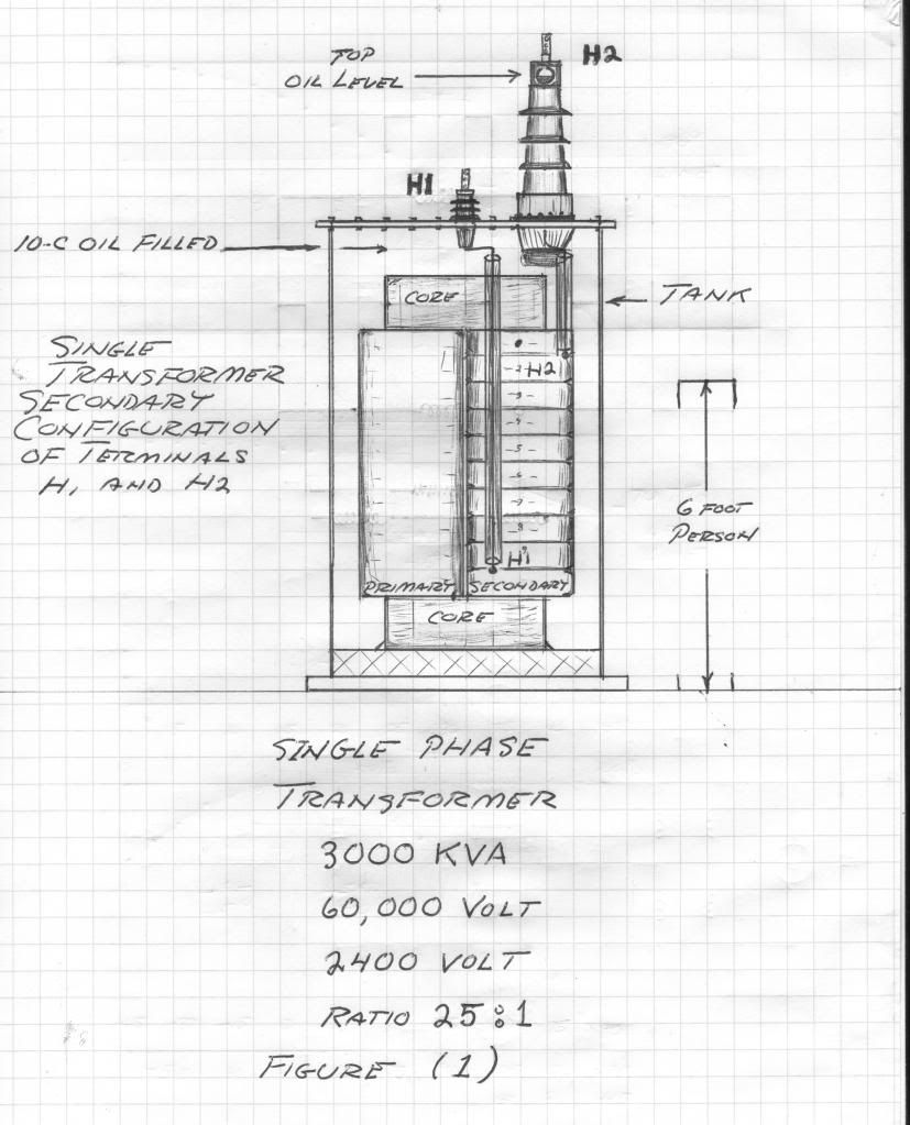
                        Today we have the good fortune of the permission to experiment in the transformer yard of a department of water and power generating station. The station station is down for maintenance and one bank of line transformers is available for our experiments. This bank has a wye connected secondary of 60 Kilo-Volt line to neutral voltage. The primary windings are in a delta connected 2.4 KiloVolt line to line voltage, these to the generators.

                        Now one transformer is removed from the bank, its 2.4 Kilo-Volt primary will remain unused. The secondary coil is asymmetrical for grounded neutral connection. Hence the secondary coil has a high voltage bushing for line connection, and a distribution voltage bushing for neutral connection. See Figure (1). This is an "odd order series" winding, or a "quarter wave" type configuration.

                        This single phase power transformer has the following specifications:
                        Full Load Capacity: 3000 KiloVolt - Amperes
                        Secondary Voltage: 60 KiloVolts
                        Basic Impulse Level: 300 KiloVolts

                        Measurements on the secondary windings give the following results:
                        D.C. Winding Resistance: 24 Ohms
                        60 cycle Winding Reactance: 60 KiloOhm

                        Hence the Inductance is derived as: 160 Henry

                        And the ratio of reactance to resistance of this winding is derived as:
                        2500 Numeric

                        A 60 cycle condenser bank is now constructed to give an equal and opposite reactance to that of the 60 KV secondary coil. At 60 KV the reactive power in this winding is:
                        60 KiloVars

                        Thus the condenser must also develop a counteracting power,
                        60 KiloVars

                        And this results from a condenser reactance of:
                        60 Kilo-Ohm
                        The same as that in the transformer winding. Finally, this condenser bank must withstand the basic impulse level developed by the secondary winding, a maximum of
                        300 KiloVolts

                        Hence established is a series connected condenser bank, of ten 30 KV units, each with a capacity of
                        .4 microFarads

                        Or a total of .04 microFarads.

                        Here now in the transformer yard is our experimental network, about 50 tons in weight.

                        The test voltage in the experiments will be 120 volts AC, 60 cycles per second, from a lighting transformer.

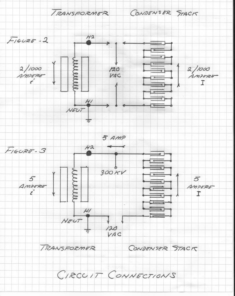
                        The first experiment is shown in Figure (2). The 120 volts is connected to the secondary winding of the transformer. The current is the voltage divided by the reactance,
                        2 mA

                        Now in place of the transformer winding, the condenser is connected the 120 volt supply. The current is also
                        2 mA

                        The Back E.M.F. of both the coil and the condenser are equal since the reactance of the coil and condenser are equal. Here however it is equal and opposite.

                        The next experimental setup is shown in figure (3). Here now the condenser is connected in series with the winding of the transformer. It is found that a current of
                        5 Amperes

                        is now being delivered by the 120 volt supply. The transformer is emitting a deep, powerful, growl and the condenser bank is crackling with static sparks. The voltage on the line bushing is measured to be
                        300 KiloVolts.
                        The maximum voltage of the transformer.

                        HOLY TESLA MR WIZARD!! WHAT HAPPENED?!!

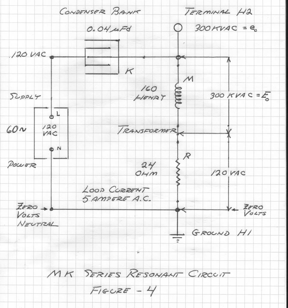
                        The electrical network utilized is shown in figure (4). It is a basic series RLC circuit;
                        Resistance, 24 Ohm
                        Inductance, 160 Henry
                        Capacitance, 0.04 microFarad

                        Shown in figure (4) is the remarkable condition that the full line voltage of 120 volts appears across the resistor, just as if the coil and condenser DID NOT EVEN EXIST. Also interesting is that the high voltage of the coil counteracts the high voltage of the condenser giving a net voltage of zero.

                        The Electromotive force developed by the coil is the current times the reactance,
                        5 Ampere, 60 Kilo-Ohm
                        300 KiloVolt

                        Likewise the electrostatic potential contained by the condenser is the current times the reactance,
                        5 Ampere, 60 Kilo-Ohm
                        300 KiloVolt

                        The real power of energy consumption is the product of the E.M.F. and current dissipated by the resistance
                        600 watt

                        The image power of energy storage is the product of the voltage developed times the current developing the voltage, E.M.F. or potential
                        1500 KiloVolt-Amperes

                        Taking the ratios gives the voltage magnification,
                        300 KV per 120V,
                        or 2500 numeric

                        And the power magnification,
                        1500 KVar per 600 Watt, or
                        2500 numeric.

                        To summarize, today in the D.W.P. transformer yard we simulated a 60 cycle Tesla Transformer in lumped parameter form. This "Tesla Coil" developed a maximum potential of 300 KiloVolts with an activity of 1500 KiloVars. Its magnification factor is 2500. This system is not able to transmit however because the sum of all the currents in this setup are equal to zero in accord with Kirchoff's Law. This is a simulation only to demonstrate the basic principles of resonance as developed by Tesla.

                        73 DE N6KPH


                        Last edited by t-rex; 06-28-2012, 01:48 PM.
                        SUPPORT ERIC DOLLARD'S WORK AT EPD LABORATORIES, INC.

                        Purchase Eric Dollard's Books & Videos: Eric Dollard Books & Videos
                        Donate by Paypal: Donate to EPD Laboratories

                        Comment


                        • Multiply Math

                          dRGreen,
                          AM Radio Station frequency = 882Khz

                          Secondary: (T-Rex)
                          Ls = 4.8*10(9)/F cm = 5442.2 cm = 54.42 meters
                          Ws = 7.6*10(7)/F cm = 86.17 cm = 862 mm
                          Radius = 431 mm
                          Hs = 1.5*10(7)/F = 17.007 cm = 170 mm

                          Extra Coil Diameter: (T-Rex)
                          We = 0.4 Ws = 862*0.4 = 344.8 mm
                          Circumference = 2piR = 1083.22 mm

                          Extra Coil: (Smokey)
                          882*(pi/2) = 1385.4*4 = 5541.77 Khz = Full Luminal
                          FREQUENCY & WAVELENGTH CALCULATOR
                          Just enter the frequency into the blank space provided and hit 'Khz'.
                          5541.77 = 54.097 meters 54097 mm (177.48')
                          Turns = 54097/1083.22 = 49.94

                          That is confirmation that calculation is correct as it should be close to 50 Turns.
                          Note Tesla's calculations show Secondary and Extra to be also nearly the same length wire used and this is the contentious issue I am having with Eric plus the 'Multiply' and not 'Divide'.
                          In this case we have Ls = 54.42 meters and Le = 54.097 meters.

                          Wire sizes used at this time are the same for both Coils at 14 awg.
                          Others should now be able to copy this method from the example above.

                          Note also that this is a Crystal Set that we are working with here and the need for a pickup head and high impedance Headphones are necessary components required.
                          The aim is to hear your selected Radio Station from the Extra Coil at a distance through transmission of an LMD wave through air that does not require contact like an EM signal does through the same pickup head and Headphones.
                          Good Luck in building.

                          Secondary 17 Turns vs 20 Turns:
                          One thing of note here is that if the Secondary is EM powered as from a Sig Gen, it is much better at turn 20.
                          If passively powered by the Telluric signal, Turn 17 is way better.

                          Going ahead with the new Extra using 20 awg for Surface Area/Mass comparison.

                          Smokey

                          Comment


                          • Originally posted by David G Dawson View Post
                            In this case we have Ls = 54.42 meters and Le = 54.097 meters.
                            That's about 108 metres total. Have you been able to receive the radio using Eric's exact circuit? And are you able to receive the signal with only the secondary using the same circuit?
                            Last edited by dR-Green; 06-28-2012, 08:49 PM.
                            http://www.teslascientific.com/

                            "Knowledge is cosmic. It does not evolve or unfold in man. Man unfolds to an awareness of it. He gradually discovers it." - Walter Russell

                            "Once men died for Truth, but now Truth dies at the hands of men." - Manly P. Hall

                            Comment


                            • impedance matching, this is where I think it's tripping up radio guys. Recall that the point here is to show that the ground current is FTL, in order to do this the receiving antenna needs to match the transmitter. If the extra coil is short it will only match the air radio waves, not the ground current.

                              So how would one design an antenna to match impedance of two different velocity propagation waves? This is a complex conjugate and a transmission line problem. This is what Eric has been talking about this whole time, not being a radio operator to begin with I'm not burdened with trying to think outside that box, however being a physicist taught quantum theory, well that's taken a paradigm shift to start to understand the true nature of the field.

                              I know Eric says one doesn't really need to understand the mathematics behind it, I disagree as there is very complex relations and simplifying the math leaves out the beauty of what's going on, heck for the most part the math doesn't exist to handle this. but understanding where the limits are with current equations on the matter really help in moving forward.

                              Comment


                              • Extra Coil Multiply

                                Originally posted by dR-Green View Post
                                That's about 108 metres total. Have you been able to receive the radio using Eric's exact circuit? And are you able to receive the signal with only the secondary using the same circuit?
                                dR-Green,
                                Again - NO!
                                By making contact with the probe head and Headphones I can hear a signal on all metal apart from the 124 Turn Extra but is weak and requires physical contact of the probe head.
                                Eric's Extra is dead even with placing the pickup capacitor right near the wire.
                                My design is able to receive at some 20" away and am now refining this distance with a new Extra with 20 awg.

                                Smokey

                                Comment

                                Working...
                                X