60 KV Transformer, Final
(1) Given in the previous transmissions is that there exists three distinct modes in which this transformer can operate.
I) As a power transformer for machine frequencies. The inductance is space scalar and the dielectric energy content is negligible.
II) As a resonant transformer for VLF frequencies. The inductance is a sine function of space and a considerable quantity of dielectric energy content exists, equal to the magnetic energy content. The capacitance is now a cosine function of distance. This resonant energy exchange is powered by a loose coupled source of Alternating Current through the primary winding.
III) As an extra coil for VLF frequencies. Again equal energies in a resonant exchange but now series fed through the neutral to earth connection. The primary coil now is inactive in this operation.
2) Some further experiments are in order here.
The DC, or static, resistance of the 60 KV secondary winding is measured to be:
24 Ohm
Handy is a car battery:
12 Volt
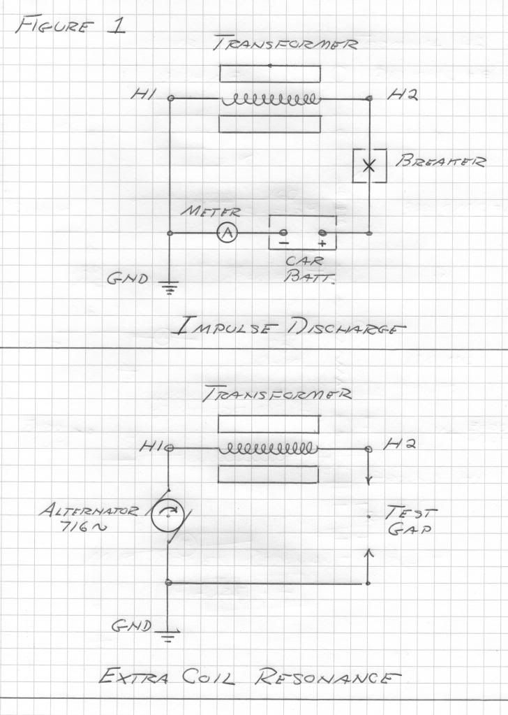
Now connecting the line, H2, terminal to its line vacuum breaker, Figure 1, and connecting the line side of the breaker to the positive terminal of the car battery, a basic current loop is formed.
The negative terminal of the car battery is connected to an ammeter and then to the transformer neutral. The neutral, H1, is grounded to station ground.
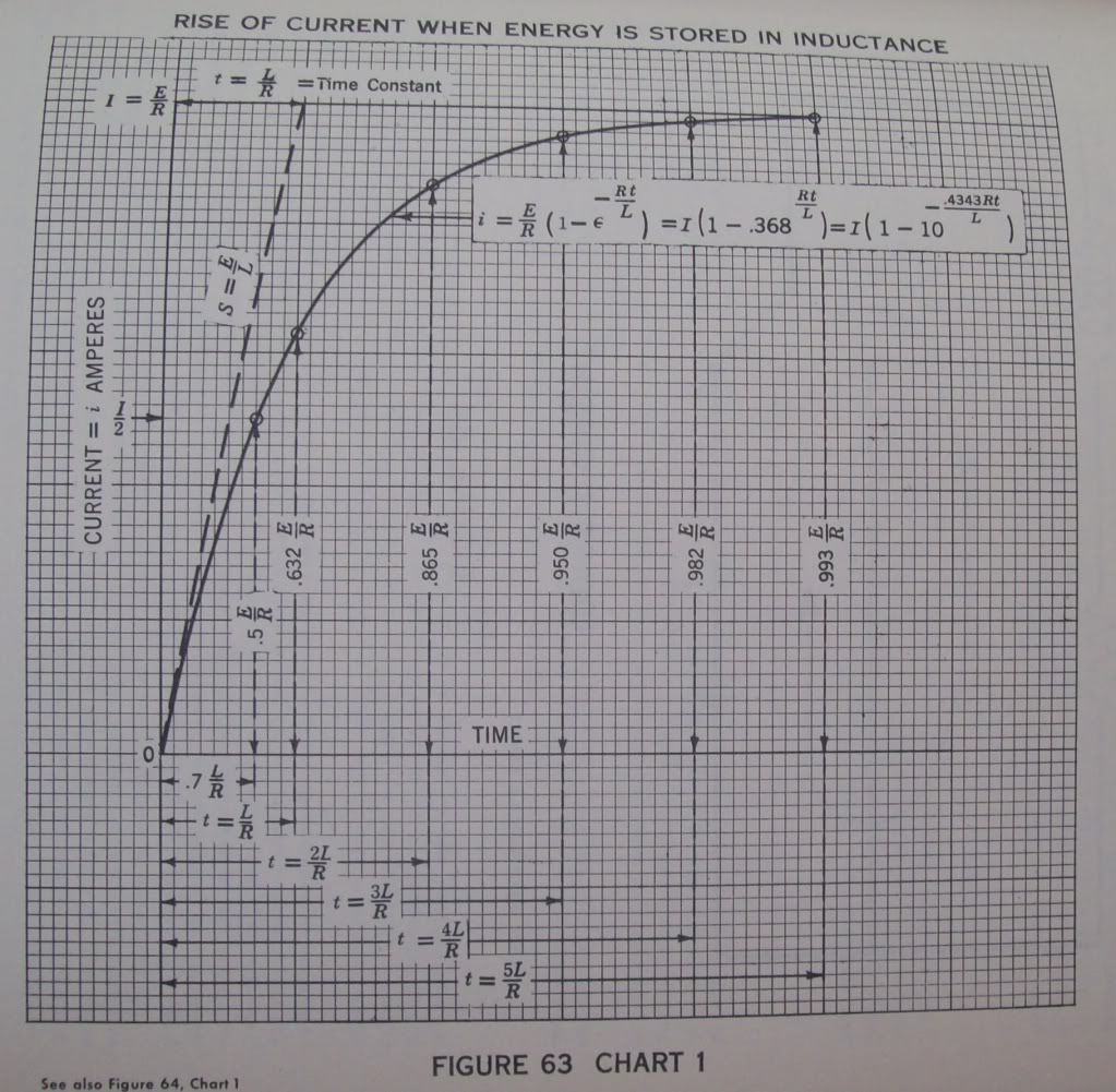
3) The vacuum breaker is closed completing the current loop, this loop a basic, L,R, circuit of 24 Ohm and 160 Henry. Upon closure a stopwatch counts time from the instant of this closure, T, equals zero. Observing the ammeter it is seen to rise very slowly. At the point when the ammeter reads
316 milliAmpere
The stopwatch is checked. The span of time to reach 63.2 percent of the maximum value is called the magnetic time constant, u. The stopwatch reads
6.7 seconds
The ammeter continues to climb, in ever smaller increments closer and closer to 500 milliAmp. It is noticed it takes over 33 seconds for the inductance to reach full charge. See figure 63.
At full charge the winding current is one half Ampere. The static winding inductance is 160 Henry. Hence the magnetic energy storage is derived as
20 Watt-second
4) Now the vacuum breaker is tripped, this instantaneously breaking the loop. A streamer several feet long erupts from the line, H2, bushing insto space. Since no escape of energy exists the magnetic energy is abruptly converted into dielectric energy at a fundamental frequency and its odd order harmonics. This was given as
716 cycles per second
The effective values of inductance and capacitance were determined to be 100 Henry
and
500 picoFarad
By the law of conservation of energy the magnetic energy equals the dielectric energy. By algebraic operation the ratio of EMF to current is the square root of the ratio of 100 Henry and 500 picoFarad,
450 Kilo_ohm
And thus from a 12 Volt car battery the EMF developed at the line terminal, H2, is derived as
225 KiloVolts peak
This assuming a sinusoidal waveform. Here the harmonics were burned off in the streamer issuing from H2.
(5) The increase in frequency from 60 cycle to 716 cycle gives an increase of the effective resistance to 72 Ohm, at 716 cycles per second. The effective inductance is 100 Henry. The reactance of this inductance at the oscillating frequency, Omega,
4500 radians per second
is derived to be Omega L or
450 Kilo-Ohm
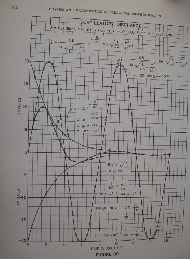
And the time constant of the 716 cycle oscillation is derived from the effective inductance in proportion to the effective resistance, L, over, R. It is however that the oscillatory energy is magnetic only half the time, the other half is dielectric. Hence the time constant is given as one half the ration of inductance to resistance, one half of
1.39
Gives the oscillatory time constant as,
.7 seconds
At this time the magnitude of the oscillation has diminished to one over Epsilon, or
36.8 percent
The oscillation becomes inaudible in about five times this, or,
3.5 seconds
See figure 60.
(6) The magnification factor of this oscillating winding is determined by the ratio of the effective winding reactance to the effective winding resistance,
450 Kilo-Ohm
to
72 Ohm
Giving
6250 numeric
The initial, or peak, current is one half an ampere this the effective value, or per square root of two, is given,
356 milliAmpere RMS
The initial, or peak, EMF is given as 225 Kilo-Volt, hence the effective value is,
159 Kilo-Volt, RMS
The product of these values gives the total oscillatory activity in the transformer winding,
56.6 Kilo-Volt-Ampere
(7) The losses in the windings are given by the square of the effective current times the effective resistance, I squared R, or the Back EMF developed by the losses is the current times the resistance, I, times, R, or
25.6 Volt
Here from are derived the basic transformation parameters in the operation of the 60 KV secondary winding as a resonant extra coil, this for an output potential of 160 KV at 716 cycles per second.
Input (H1) Power Requirement
9.1 Watt
Input Impedance, E, over, I, or,
72 Ohm
This a resistive load as seen by the source of alternating electric energy. Hence, a 10 watt audio amplifier, on the 50 Ohm output tap, will give rise to a resonant oscillation, building up over a time span of 3.5 seconds, this with an activity of 56.6 KiloVars and an electrostatic potential of 160 KiloVolts. Here established is the concept, -- "Magnification Transformer"
73 DE N6KPH

From Perrine's book "Physics and Mathematics in Electrical Communications":


(1) Given in the previous transmissions is that there exists three distinct modes in which this transformer can operate.
I) As a power transformer for machine frequencies. The inductance is space scalar and the dielectric energy content is negligible.
II) As a resonant transformer for VLF frequencies. The inductance is a sine function of space and a considerable quantity of dielectric energy content exists, equal to the magnetic energy content. The capacitance is now a cosine function of distance. This resonant energy exchange is powered by a loose coupled source of Alternating Current through the primary winding.
III) As an extra coil for VLF frequencies. Again equal energies in a resonant exchange but now series fed through the neutral to earth connection. The primary coil now is inactive in this operation.
2) Some further experiments are in order here.
The DC, or static, resistance of the 60 KV secondary winding is measured to be:
24 Ohm
Handy is a car battery:
12 Volt
Now connecting the line, H2, terminal to its line vacuum breaker, Figure 1, and connecting the line side of the breaker to the positive terminal of the car battery, a basic current loop is formed.
The negative terminal of the car battery is connected to an ammeter and then to the transformer neutral. The neutral, H1, is grounded to station ground.
3) The vacuum breaker is closed completing the current loop, this loop a basic, L,R, circuit of 24 Ohm and 160 Henry. Upon closure a stopwatch counts time from the instant of this closure, T, equals zero. Observing the ammeter it is seen to rise very slowly. At the point when the ammeter reads
316 milliAmpere
The stopwatch is checked. The span of time to reach 63.2 percent of the maximum value is called the magnetic time constant, u. The stopwatch reads
6.7 seconds
The ammeter continues to climb, in ever smaller increments closer and closer to 500 milliAmp. It is noticed it takes over 33 seconds for the inductance to reach full charge. See figure 63.
At full charge the winding current is one half Ampere. The static winding inductance is 160 Henry. Hence the magnetic energy storage is derived as
20 Watt-second
4) Now the vacuum breaker is tripped, this instantaneously breaking the loop. A streamer several feet long erupts from the line, H2, bushing insto space. Since no escape of energy exists the magnetic energy is abruptly converted into dielectric energy at a fundamental frequency and its odd order harmonics. This was given as
716 cycles per second
The effective values of inductance and capacitance were determined to be 100 Henry
and
500 picoFarad
By the law of conservation of energy the magnetic energy equals the dielectric energy. By algebraic operation the ratio of EMF to current is the square root of the ratio of 100 Henry and 500 picoFarad,
450 Kilo_ohm
And thus from a 12 Volt car battery the EMF developed at the line terminal, H2, is derived as
225 KiloVolts peak
This assuming a sinusoidal waveform. Here the harmonics were burned off in the streamer issuing from H2.
(5) The increase in frequency from 60 cycle to 716 cycle gives an increase of the effective resistance to 72 Ohm, at 716 cycles per second. The effective inductance is 100 Henry. The reactance of this inductance at the oscillating frequency, Omega,
4500 radians per second
is derived to be Omega L or
450 Kilo-Ohm
And the time constant of the 716 cycle oscillation is derived from the effective inductance in proportion to the effective resistance, L, over, R. It is however that the oscillatory energy is magnetic only half the time, the other half is dielectric. Hence the time constant is given as one half the ration of inductance to resistance, one half of
1.39
Gives the oscillatory time constant as,
.7 seconds
At this time the magnitude of the oscillation has diminished to one over Epsilon, or
36.8 percent
The oscillation becomes inaudible in about five times this, or,
3.5 seconds
See figure 60.
(6) The magnification factor of this oscillating winding is determined by the ratio of the effective winding reactance to the effective winding resistance,
450 Kilo-Ohm
to
72 Ohm
Giving
6250 numeric
The initial, or peak, current is one half an ampere this the effective value, or per square root of two, is given,
356 milliAmpere RMS
The initial, or peak, EMF is given as 225 Kilo-Volt, hence the effective value is,
159 Kilo-Volt, RMS
The product of these values gives the total oscillatory activity in the transformer winding,
56.6 Kilo-Volt-Ampere
(7) The losses in the windings are given by the square of the effective current times the effective resistance, I squared R, or the Back EMF developed by the losses is the current times the resistance, I, times, R, or
25.6 Volt
Here from are derived the basic transformation parameters in the operation of the 60 KV secondary winding as a resonant extra coil, this for an output potential of 160 KV at 716 cycles per second.
Input (H1) Power Requirement
9.1 Watt
Input Impedance, E, over, I, or,
72 Ohm
This a resistive load as seen by the source of alternating electric energy. Hence, a 10 watt audio amplifier, on the 50 Ohm output tap, will give rise to a resonant oscillation, building up over a time span of 3.5 seconds, this with an activity of 56.6 KiloVars and an electrostatic potential of 160 KiloVolts. Here established is the concept, -- "Magnification Transformer"
73 DE N6KPH

From Perrine's book "Physics and Mathematics in Electrical Communications":


 You mentioned books on non-linear oscillation, I happen to have a copy of Chihiro Hayashi's Nonlinear Oscillations in Physical Systems. Not sure if you're getting that book already or not but if you want I could photocopy some sections which you find important.
Comment