Generally you do not want to create inter-winding capacitance, that lowers the impedance and lowers the voltage and in some cases lowers the magnification factor. In the extra coil you want the lowest capacity possible. That's why Tesla used coils of equal width and height. If anything litz wire decrease capacitance. It creates less flat plate area.
Announcement
Collapse
No announcement yet.
Eric Dollard
Collapse
This is a sticky topic.
X
X
-
Ok, I think these are the numbers.Originally posted by Geometric_Algebra View PostHey, nice work (real science is done on the floor, with beer... cans).
The 64% factor is a result of the (2/pi) scale factor you are using to design the secondary length.
Use the height to width ratio of your coil (0.2) to get the free space propagation constant (say eta_free=1.02). From measurements you have calculated the measured propagation constant which is 68% or 0.68 (say eta_measured=0.686). Now you can take the ratio of those two to get r=eta_free/eta_measured=1.487 (approx.), and then use it to compute your coil burden capacitance Cb=r^2*C_self. Eric or someone else will have to clarify the eta ratio further.
V_lum = 299.792.458 m/s (speed of light)
eta_free=1,02 (height / diameter coil is 0,2) (from the table)
V_free = 305788307 m/s (eta_free * V_lum)
This gives:
F_free = 3037935 Hz (2/pi*V_free/4L)(L= Length wire =16,02 m)
Measured:
F_measured = 3210000 Hz
This gives:
V_measured = 323107777 m/s (pi/2*F_measured*4L)
eta_measured = 1,08 (V_measured/V_free=F_measured/F_free)
So eta_measured is larger than eta_free. The measured speed is faster than the free speed. The measured frequency was higher than the calculated frequency!
r = 0,94 (eta_free/eta_measured)
So Cb is smaler than C self.
Now there might be a small difference in aspect ratio because the 8 corners are not a real circle to explain for the smaler than one ratio but I think the conclusion could be that this litz wire does very little burden the coil with capacity!
I believe Eric said the effective surface area is smaller with litz wire.
Leave a comment:
-
Hey, nice work (real science is done on the floor, with beer... cans).Originally posted by orgonaut314 View PostI have a few questions and remarks.
-I could not do a very accurate frequency measurement so the magnification is sort of guesswork. I think my analogue frequency generator is not very stable.
-I calculated the free space propagation using Eric's coil notes. However I do not understand how I can find this in the 'percent luminal velocity' table. Using the ration 20% for height to width I get 102% as a factor while it should be 64% ???
What am I not understanding here? Is the table wrong or should I use 10% while my height is 5 and mij width is 25?
-If the conclusion is right that the measured propagation is faster than the free space propagation would that mean that the litze performs very wel?
Regards and thanks in advance.
The 64% factor is a result of the (2/pi) scale factor you are using to design the secondary length.
Use the height to width ratio of your coil (0.2) to get the free space propagation constant (say eta_free=1.02). From measurements you have calculated the measured propagation constant which is 68% or 0.68 (say eta_measured=0.686). Now you can take the ratio of those two to get r=eta_free/eta_measured=1.487 (approx.), and then use it to compute your coil burden capacitance Cb=r^2*C_self. Eric or someone else will have to clarify the eta ratio further.Last edited by Geometric_Algebra; 11-17-2013, 01:44 AM.
Leave a comment:
-
Hmm I think the 64% was the 2/pi factor for the longitudinal wave in relation to the transversal wave. That makes sense
Leave a comment:
-
I have a few questions and remarks.
-I could not do a very accurate frequency measurement so the magnification is sort of guesswork. I think my analogue frequency generator is not very stable.
-I calculated the free space propagation using Eric's coil notes. However I do not understand how I can find this in the 'percent luminal velocity' table. Using the ration 20% for height to width I get 102% as a factor while it should be 64% ???
What am I not understanding here? Is the table wrong or should I use 10% while my height is 5 and mij width is 25?
-If the conclusion is right that the measured propagation is faster than the free space propagation would that mean that the litze performs very wel?
Regards and thanks in advance.
Leave a comment:
-
update
Just got back from spending a few days at EPD Laboratories with Eric, John P. and others. Have some pics and videos and other exciting things to post, but have to catch up on some sleep. Only 4 hours of sleep and almost 1000 miles (that is only one way) so will post soon as I can!
Leave a comment:
-
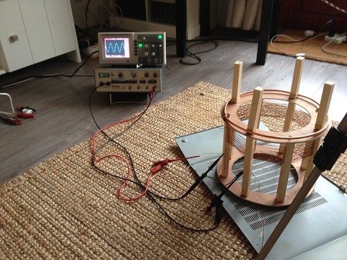
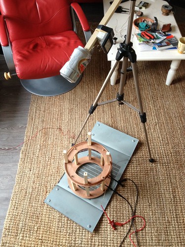
I optimized the setup by placing the meter at a larger distance with the can facing the coil and placing the coil at a bigger distance form all other objects.
Free space propagation = 64%
Measured propagation = 68%
Measured frequency = 3210 kc
LSB = 3185 kc
USB = 3240 kc
Magnification factor = 58
Coil height: 5,1 cm
Coil diameter: 25,5 cm
Number of turns: 20

Leave a comment:
-
Ok I get the following numbers (detaching the Ampere meter from the ring).
F = 3,11MHz (center frequency)
n=77,75 (magnification)
I will plot a detailed sheet later! Thanks for the reply
Designed for:
W N L H
25,5 20 1602 5,1
F
2,995857 MHzLast edited by orgonaut314; 11-14-2013, 02:21 PM.
Leave a comment:
-
Nice work orgonaut. A smaller can will have less capacitance so it will affect the frequency. If the signal is too high for your meter turn the input signal down.
The meter and can will also burden the coil a bit so you could use the same setup as the extra coil test setup, with no physical contact between the meter and the coil. This will also solve the problem of peaking the meter as well as resulting in a slightly higher frequency.
-----
In other news, it's that time of year again that the World Rally Championship comes down my way, so I'm off to spend a few days camping in the forest.
http://www.walesrallygb.com/home.php
Leave a comment:
-
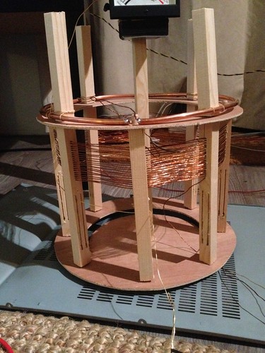
I use seven very thin wires hardly twisted so I would not call it litze. Because it is very thin I hope the skin effect will not slow the wave down. The total volume was matched to the primary, this way the surface area was larger than with foil but there is less dielectric material!
Leave a comment:
-
I've done a very first measurement on the resonance of the secondary coil and found the measurement to be 2.98MHz while it was designed for 2.99MHz!
The resonance is very sharp peaked and the 100uA meter gets to much signal. Perhaps a smaller can could fix that?
I will do some calculations on Q and F and see how it performs
This is fun
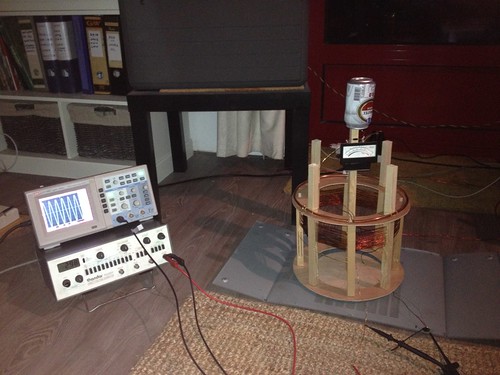
I use seven very thin wires hardly twisted so I would not call it litze. Because it is very thin I hope the skin effect will not slow the wave down. The total volume was matched to the primary, this way the surface area was larger than with foil but there is less dielectric material!
Leave a comment:
-
Extra coil frames finished:

Winding:


-----
Full scale extra coil measured propagation (Colorado Springs Notes) = 122.5851%
Provisional test results, to be redone more thoroughly
Extra coil (#1) scale model measured propagation:
Direct = 117%
10pF = 123%
Leave a comment:
-
Eric Dollard - Interview 11/5/2013
Interview with Eric from Nov 5, 2013:
Eric Dollard live interview by Aaron Murakami - November 5, 2013 - YouTube
I apologize for the audio, but it was a phone conference. Eric
answers a wide range of questions from the audience.
Leave a comment:
-
Nice picture of Nikola Tesla. To be honest I was a little shocked when I heard that Eric thought of Arthur Mathews as a disinformation agent. I knew that story was to fantastic to be true and Eric made a lifetime study on Tesla but I even saw pictures of an old man in Canada that says he is Arthur. But than Arthur says not to believe the biography's and that might be a very clever way to hide the facts that he probable never was Tesla's assistent? I have to read 'Prodigal genius' and 'Men out of time'. Is there no mention of Arthur in these books? The whole Venus cult being nonsense? Wow.Originally posted by T-rex View Post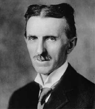
"These men are to me nothing more than microbes of a nasty disease." - Nikola Tesla
Leave a comment:
Leave a comment: