Announcement

Collapse
No announcement yet.

Eric Dollard

Collapse
This is a sticky topic.
X
X
 
  • Filter
  • Time
  • Show
Clear All
new posts

  • What he is calling gravito Eric is posable calling dielectric. They both see a pair of waves. Interesting is that he thinks the magnetic field is carrying the gravito field. I think we would say that the electromagnetic wave comming from the magnetic antenne would have a dielectric field at right angles to the propagation of the poynting vector. So it might be spiralling around the poynting like he thinks when he constructed his wave model that was mainly an inspiration he says.

    That would be a new idea for wireless transport of the electromagnetic and dielectric field? I mean we mostly work with field that have only dielectric components but normally both must be present?
    Comment


    • Originally posted by jpolakow View Post
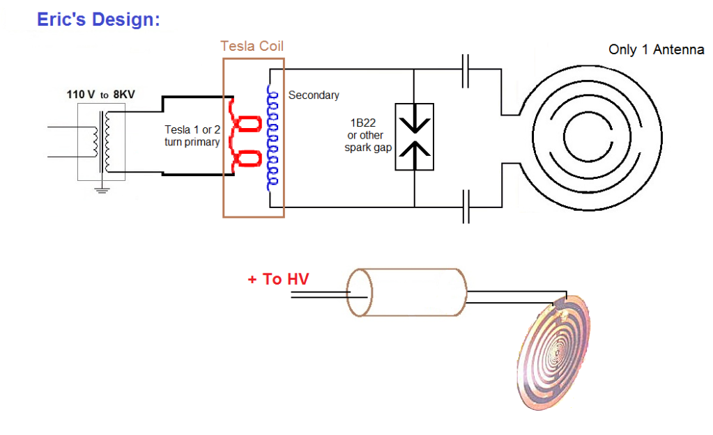
      Now it is time to examine what Eric’s ideal version of what a multi-wave oscillator would be. This is Eric’s design separate from Lakhovsky’s work. To produce a true multi-wave oscillation, you need to produce a magnemotive force (current) in the outermost ring. So naturally the antenna would not be one wire connected, it would be connected on both ends:

      In this design you can get the most magnemotive force(current) flowing in the outer ring, which produces an EMF in the center rings through mutual induction. Each ring oscillates and transmits its own resonant frequency, thus having a true multi-wave, or multi-frequency effect. With this version there is no receive antenna, only one antenna is needed to transmit the multiple wavelength oscillations. This is the way to actually produce a multi-wave oscillation, if that is what Lakhovsky was after. Also the transmit antenna is not limited to producing the individual wavelengths of its component rings. Listed in the additional links section are a few videos, in one of the videos Eric talks about “phantom antennas”. Note in the above picture the flat antenna is markedly different from the tubular ring construction seen in Lakhovsky’s originals, this is an original design by Eric Dollard.
      I would like to make one of these for a friend of mine who is sick. There are many instructional sites on making PCBs, so that shouldn't pose too much of a problem, but my biggest concern is tuning the primary coil. I understand that the other coils are log periodic following the golden ratio, but that won't mean much if the primary is out of tune, will it? What frequency should the primary coil be? (and I'd have to assume the PCB is rather uniform in its capacitance)

      I should also mention that my friend has a large metal implant. Does anyone know if that or any near-by electronics would cause any complications, or do any harm to the electronics?

      Comment


      • http://www.zephyrtechnology.com/MWO_...pril_2009_.pdf

        This document contains a template that you can print and should give you the exact sizes. I found the site it came from pretty good.

        Comment


        • Originally posted by orgonaut314 View Post
          http://www.zephyrtechnology.com/MWO_...pril_2009_.pdf

          This document contains a template that you can print and should give you the exact sizes. I found the site it came from pretty good.
          Thank you, but after reading through the website that PDF came from, I don't think I can trust it very much. The template didn't even mention any sizes, so if the DPI of my printer differs from the person who made it, they'd be tuned differently. And it didn't include the strips on backface needed to make the PCB into capacitors. With different size/materal board between the layers there'd be different capacities. Isn't it supposed to basically be an LC circuit? And what's with the overly complicated schematic for the power supply?

          Comment


          • Lines of Force

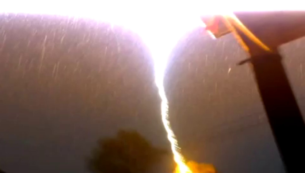
            Recently there has been a video on You-tube of a Lightning strike hitting the ground nearby. (URL – I forgot to copy it, will find and provide later).

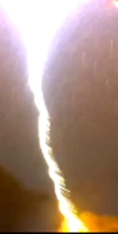
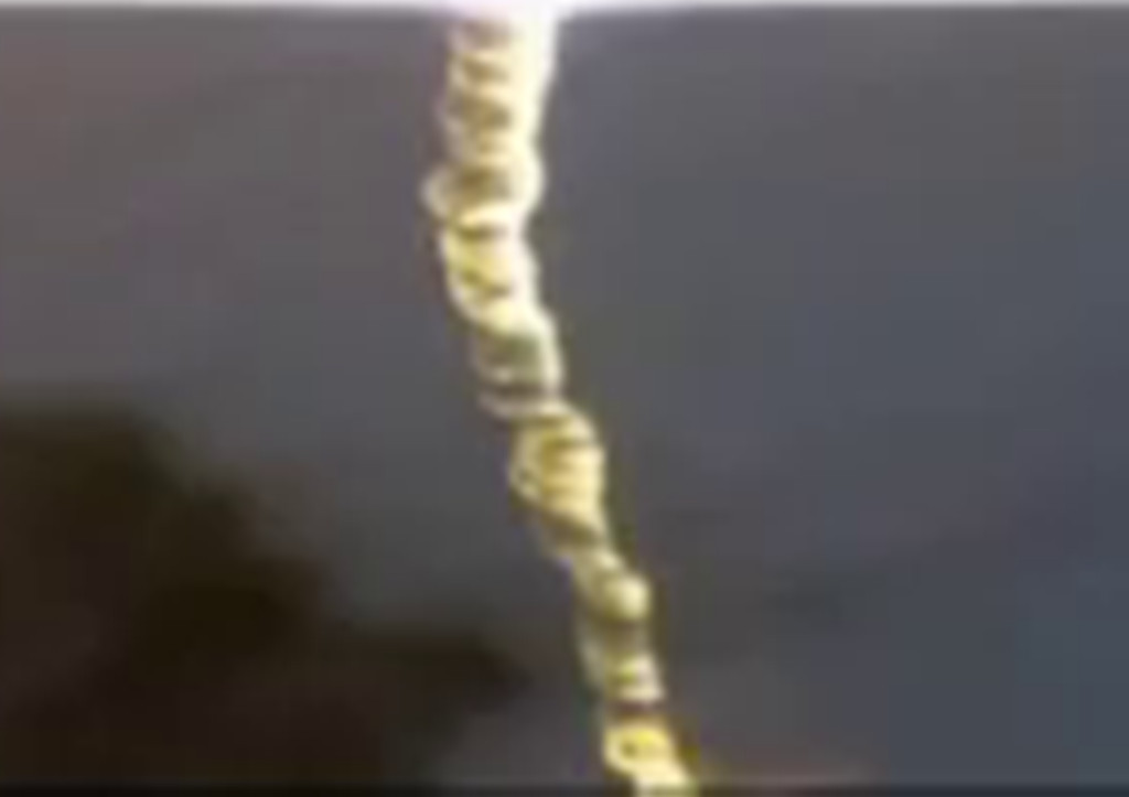
            There are lots of lighting pictures and videos out there, but look at the screenshot pictures of this one! Saturation of Dielectric Lines of Force!

            You can clearly see the spiral form in the lightning discharge! It looks amazing with it almost looking like a solid water spout, a twister or some twisted rope. The Golden Ratio is clearly seen.

            A Billion Watts of Natures Power:

            Original screenshot:
            ]
            Close up:

            Close up of frame two:


            Sputins
            Last edited by Sputins; 01-06-2014, 01:11 AM.
            "Doesn't matter how many times you kick the coyote in the head, it's still gonna eat chickens". - EPD

            Comment


            • Yeah Sputins, Beautiful pictures, any chance of the video ? A hint to search ?
              The hard conduction times make what I call "power cones", I posted a picture of
              much less quality some time ago.

              They look like electrical tornado's alright.

              In this video of my transformer working with a rotary spark gap we can see
              the hard "white" rope like conductions definitely spin up and fly apart, if the
              break out point is placed near the center of the terminal I get double spirals
              intertwined that can be seen to throw themselves apart after spinning up.

              We can see as I vary the BPS at certain break rates there is more tendency for the white rope to continue longer.

              Tesla coil test 2 - YouTube

              .
              Attached Files

              Comment


              • Originally posted by Farmhand View Post
                Yeah Sputins, Beautiful pictures, any chance of the video ? A hint to search ?
                Farmhand, try searching: “Hilarious lightning strike”. It is a fairly new video. I’ll find the link again when I’m home tonight and have a spare 5 minutes or so. I’ll check out your video too. Comment later. (Youtube blocked at work).
                "Doesn't matter how many times you kick the coyote in the head, it's still gonna eat chickens". - EPD

                Comment


                • Yeah I found the video but it has some profanity so I dare not link it, though
                  there is no need just search "Hilarious Lightning strike". It hit in Ipswich,
                  Queensland, nice strike. People need to be wary that the window they watch
                  the storms from is not near where the electrical feed comes to the house.

                  The guy done well or got lucky to catch the parts he did. Awesome. I bet
                  they felt alive after that one.

                  I was doing it one day and a bolt hit the pole, then a ball of lightning rolled
                  down the lines and dropped onto a passing car made it splutter then rolled off
                  and dissipated when it hit the ground in the gutter. It could just as easily
                  have rolled down the feeder to the window as the feeder line was above the
                  window I was looking out of. My reaction was more severe, I jumped back into
                  a wall behind me and being a solid wooden wall I bounced right back off it
                  back to the window to see the ball.

                  Kinda like this. But not so firey. One I seen was more blue. It moved the same but not far before dropping.
                  Fireball on the lines is probably fairly common when serious very electrical storms are around.
                  Caught on Tape: Fireball Blazes Across Electrified Power Lines - YouTube

                  Ducking for cover is a good reaction.

                  On the day I was actually watching multiple bolts hitting the lightning rod on a
                  fire observation platform, about 3 clicks away, it was taking repeated hits
                  with hardly any noise, I can only guess because it had good conduction to
                  ground, it kinda grizzled rather than went bang or crack as the associated
                  thunder usually does. I was having a good time at first.

                  It kinda sounds like that bolt got fairly low resistance to ground as well. Buku current.

                  Thanks for the Screen captures. Spectacular.

                  ..
                  Last edited by Farmhand; 01-06-2014, 04:54 AM.

                  Comment


                  • Originally posted by Dingus View Post
                    Thank you, but after reading through the website that PDF came from, I don't think I can trust it very much. The template didn't even mention any sizes, so if the DPI of my printer differs from the person who made it, they'd be tuned differently. And it didn't include the strips on backface needed to make the PCB into capacitors. With different size/materal board between the layers there'd be different capacities. Isn't it supposed to basically be an LC circuit? And what's with the overly complicated schematic for the power supply?
                    Hi, I think you would have to print the drawing on A4 or A3 as the text says (didn't reread it). As for the power design. Here is the thing. The powerunit is just a spark gap. Eric used spark gaps from diathermy machines, they are something like this one with a Ford bobine.
                    The Lakhovsky antenna is in fact the primary from Tesla just like the hairpin was a first primary design by Tesla. Tesla went beyond. But that does not mean the hairpin or the Lakhovsky does not work.
                    By the way Lakhovsky's antenne is meant to resonate on a large number of frequencies the sparks start all these frequencys and the harmonics. If you just make a ring with diameter 30 cm you have a right frequency there.
                    That site might look like not much but the orgone stuff is pretty impressive. The author used to sell it but made everything free in an attempt to have so much people make these things that they can not be stopped anymore.
                    Succes!

                    Comment


                    • Mwo

                      Originally posted by Dingus View Post
                      I would like to make one of these for a friend of mine who is sick. There are many instructional sites on making PCBs, so that shouldn't pose too much of a problem, but my biggest concern is tuning the primary coil. I understand that the other coils are log periodic following the golden ratio, but that won't mean much if the primary is out of tune, will it? What frequency should the primary coil be? (and I'd have to assume the PCB is rather uniform in its capacitance)

                      I should also mention that my friend has a large metal implant. Does anyone know if that or any near-by electronics would cause any complications, or do any harm to the electronics?
                      @Dingus
                      The Lakhovsky Multiple Wave Oscillator Handbook put out by Borderland Science (Tom Brown) is a good resource to start with. In this book is Eric’s ‘Lakhovsky’ Golden Ratio (Logarithmic) antenna design. There are a number of circuits in that book which Eric drew some not credited to him as such, but they are clearly his, from the hand writing & drawings. Then there is Eric’s updated circuit that John P posted.

                      As for the antenna, the first ring is just like a single turn Primary coil on a spark-gap Tesla coil. The thing it was Eric’s idea was to make the antenna in a logarithmic form according to the Golden Ratio. (1.618 or 0.618) (Same idea for the extra coil wire spacing of 62%, an approximation for 0.618)

                      So building the antenna on the Golden Ratio formula is likely to be more healing to the body. With luck, if the antenna is in Golden Ratio relation, the complex harmonics is also likely to be Golden Ratio in relation?

                      A homemade unit could easily be made, doesn’t have to be powerful, just as long as you have a resonant condition in your Tesla Coil and a spark gap (1B22 would be a bonus) to provide a broad spectrum of frequencies / harmonics, build it according to the Golden Ratio.

                      Likely a single turn primary of that size is going to have a very low inductance of just a couple of micro henrys. So if you can determine what your centre frequency is approximately out of your Tesla Coil, design the primary tank circuit around that. Make the resonant parameters approximately fit. If your frequency in the range of 0.5 to 2Mcps and you have say 3 micro henrys of inductance, a resonant tank circuit capacitor will likely be somewhere between a 0.002 and 0.04uF. Use variable capacitors if necessary to seek it out, once found replace with nearest fit, fixed capacitors.

                      Yes this device would likely interfere with local electronic devices. Not sure about the metal implant.

                      Good luck.
                      Last edited by Sputins; 01-07-2014, 04:23 AM.
                      "Doesn't matter how many times you kick the coyote in the head, it's still gonna eat chickens". - EPD

                      Comment


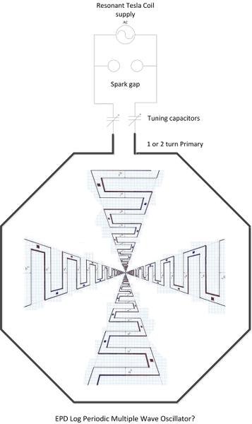
                      • In all likely-hood one might use a one or two turn spark-gap (resonant) primary coil and enclose Eric's Golden Log Periodic Series Antenna design inside and maybe similar things might be possible?

                        Last edited by Sputins; 01-07-2014, 05:07 AM.
                        "Doesn't matter how many times you kick the coyote in the head, it's still gonna eat chickens". - EPD

                        Comment


                        • I think your spark's can have a frequency of 50hz or 60hz. The resonance comes from the spark energy discharging in the natural resonance of whatever you have. So I think you don't have to worry about resonance and the Tesla coil is just there to make the very high voltage?
                          That is how I understand the spark thing. With the crystal radio we don't use sparks so we have to tune.

                          Comment


                          • Speaking arrangement

                            without a large R&D budget a demonstration along with lecture can still of a importance, recall early video made in Humbolt county with dear friends called classic now.


                            For example here is a demo video which needs more lecture.
                            turning the handle is what makes the demo model work without within practical budget. What would be nice to know from Eric Dollard in his own terminology and math how to differentiate.

                            Tesla coil "the true secret" how it was really used. - YouTube

                            This may bring about an irish temper because of dealing alot of theoretical mis-information can be frustrating. I'd like to show respect for the video, I place it here as an example or tangible connection that verbal alone is not as stimulating as demonstration together with lecture.

                            Comment


                            • MWO & Tesla Hairpin

                              Hello Dingus,
                              Would suggest you use a Neon or Furnace high voltage transformer to achieve the initial 8 kv from the 110/240 volt Mains.
                              These should be available on Ebay but not in Australia for the Furnace type - more in use in the colder Countries.
                              Have two here, one 10 kv and the other at 12 kv untried.
                              The 10kv was used for a Tesla Hairpin across a sparkgap and was most successful.
                              Caps used were TDK 4700 pF doorknobs at 12 kV.
                              1B22s are still available from Nebraska Sales but I used flat Carbon rods out of 'D' batteries and made the gap adjustable and worked well.
                              SOLD OUT1! but smaller 1B23s still available at US$15.

                              In an attempt to keep this simple would be using the Antenna made up from 1/4" or 3/8" Copper pipe formed into the Golden Ratio design that John Polakowski presented from Eric.
                              Standard 'U' fittings to attach it to a wooden backing but would raise it slightly with an insulator like pcb material to reduce prospect of arcing and burning the wood.

                              Will put up some pictures of the Tesla Hairpin to give you some construction ideas as this is actually all a very simple one to construct and works well.
                              I came away from the Hairpin feeling elated as I was probably also being dowsed in healing rays just as from a real MWO.
                              Later on this one with the pics.

                              Smokey

                              Comment


                              • Tesla Hairpin

                                Tesla Hairpin:
                                Some pictures of the Hairpin.
                                These are some of the Carbons that are available with home-made Spark Gaps that work well.
                                Big Carbons were used in the old Movie projectors and have now got a full 12" tin of these in Copper sleeves.
                                Small Carbons taken from old batteries - not all batteries use Carbons today but the red Eveready 'Heavy Duty' 'D' & 'C' still do and what I am using in the Hairpin.


                                Uploaded with ImageShack.us

                                Two shots of the setup showing how simple it all is:


                                Uploaded with ImageShack.us


                                Uploaded with ImageShack.us

                                Some pages back in this Forum shows an Oscilloscope picture of the spark.
                                This is the one you grab hold of the live ends of the light bank and can go deposit it into a bowl of water and not get zapped while the lights still shine brightly under water.
                                There is more that I should be doing with this unit and may even build an Antenna and use as a MWO.

                                This is another option from the BSRF MWO book compiled by Thomas Brown and I have all the parts for this one too but not built as yet.


                                Uploaded with ImageShack.us

                                Hope this helps.

                                Smokey

                                Comment

                                Working...
                                X