CIG/Hendershot
Cosmic Induction Generator:
John,
Excellent work and thank you for all the detail which should make a replication possible.
Did Eric ever consider using the large Carbon anode types like the 805, 813 or was it that the 4-250A/5D22 were simply available at the time from RCA?
Any input here would be appreciated on the 'finals' selection.
Don't think I can manage a direct replication but a smaller scale would be possible.
Tesla had a thing for Carbon in being a receptor of the 'Warmth Ether' and the reason for my question.
Geometric - good input, Thanks!
Hendershot Generator:
Problem with the 'resonator' and have moved over to a non-synchronous 4/6v multivibrator as I now have two transformers as used with the vibrators.
Home-made capacitors are working well at the 7,800 pF capacity and have wooden paddle-pop sticks to keep the values matched between the two.
Mentioned over at the 'Hendershot' Forum that I managed some 11,000 volts after connecting the vibrator into the Hendershot circuit and accidentally caused an arc/spark/plasma which I manipulated with some good pictures.
At this point I would say that Lester fell short of a truly major discovery by not including a plasma gap in his design and working on that at this time.
The geometry of his design appears to be supporting an 'impulse discharge' or simply 'white noise' as that is what the vibrator would be introducing in this case as their is no supression as would be the case for a power supply.
May be the basketweave/Caduceus is also acting as an Aetheric translator as 11,000 volts from a 4 volt input requires some profound brain draining and this is really NOT a Tesla type coil as in an Ignition coil.
Attempted to edit my last Post x3 with the correct URL but no indication that I have done so and reluctant to Post any pictures.
Image Shack appear to have changed their base system and not working as I expect it to and Energetic is also not responding as expected.
Will be getting back to the CSI shortly.
Built a Crystal Set that was said to be Hendershots (Utility Engines) but most disappointed as it was well and truly out perfomed by my twin 1N34 probe head without the use of coils and I am able to sense both TEM and LMD.
Keep up the good work all as we are still active here!
Smokey
Announcement
Collapse
No announcement yet.
Eric Dollard
Collapse
This is a sticky topic.
X
X
-
Geometric Translators
Hello Tom Brown,
Aetheric Weather Engineering:
Not sure how to get hold of you but using this medium in an attempt as you were here earlier.
I am in Australia with some of the TJ Constable rotating devices built from reading his books 'Loom Of The Future' and 'Cosmic Pulse Of Life' and his associated pictures but have only just realised that I have been operating these devices incorrectly and asking if you may have some further information that may be of assistance.
The pHi devices are only rotated at about 1.5 to 2 rpm but I have been rotating at quite a fast pace and realise now through further research that I am wrong.
There is a desire to 'catch' the Aether and this can only be achieved at a SUBTLE pace with pHi devices and not at the speed of an 'impulse discharge' like the 'Ellipse' devices.
I also have just discovered that TJ was at Landers at the Integratron when Eric was there and would like further input from him if possible.
Great minds, great achievers, all together and what a picnic that must have been!
Your videos with Eric made at the Psychotronics Association also made mention of TJC and his work.
We have a massive Drought on our hands here which is probably the worst that I can personally recall for my area but is much broader than that and covers all of the Eastern States from about Latitude 35 north.
I am looking forward to producing that 'bump' referred to by TJ in your 'Loom' article to help in removing these static Aetheric conditions that Wilhelm Reich would call DOR.
Some of the other TJ devices like the 'Apache' and the 'Spider' appear to be fast rotating but mine are of the 'pHi' type and not the 'Ellipse' type - two technologies in use here.
I have also just realised that we are at an 11 year Solar cycle and this ties in with cyclic Drought events here which I have traced back through the archives to 1957 and personal experience.
Makes the rectifying job just that little bit more difficult.
What my question would be is at what RPM were these devices used at by TJ as there is no indication in all the documentation for a speed.
I currently have 3 devices rotating in a passive (non-moving) experiment, two 'Triggers' 4/7 & 6/10 at 45º and a 'Termite' doing 90º horizontal sweeps.
ImageShack Album - 49 images
These are all fed from the one power supply at the slowest possible RPM but feel I need to go slower than current and probably need to use gearing or servo motors.
Hoping you can be of assistance.
If anyone can direct me straight to Tom it would be most appreciated.
Thanks and all the best.
Smokey
Leave a comment:
-
Hi JDIonico, With respect can I ask ? What proof of concept do you refer to.Originally posted by JDIonico View PostJohn, just a note of appreciation from an on-looker. I sent some funds to support Eric's work a few months ago, then I heard about all the antagonism, and was worried that once again that old pattern that seems to trail Eric was at work again, where disruptive elements destroy Eric's work and progress.
I don't have the technical expertise to understand most of what is being said here - I'm hoping that there will be an observable and well documented proof of concept that can not be suppressed because it is "out there" via this forum.
I'm also hoping that this proof of concept can be standardized and perhaps also simplified so that people like me can replicate it and generalize the dissemination and use of this technology.
This is obviously a labor of love for you and Eric and all your co-workers. I suggest that standardized how-to instructions and perhaps even parts be sold to people like me as a means to generate funds to support the work while it gets disseminated.

JD
As in proof of concept of what exactly. You obviously have something specific
in mind but do not mention what it actually is that you hope to see proof of
concept of. To the average reader it's a riddle or mystery. Could you be more
specific about what exactly the effect, process or result it is that the proof of
concept will prove ? Also if for a given example what would be considered
proof of concept ?
ie. With say for eg. the "Cosmic Induction Generator", what is the desired result ? what is
the device intended to prove.
Cheers
P.S. It seems to be rather a strange situation. Isn't John (jpolakow) supposed to be one of the "nefarious group" ?
..Last edited by Farmhand; 10-19-2013, 09:50 PM.
Leave a comment:
-
Thank You
John, just a note of appreciation from an on-looker. I sent some funds to support Eric's work a few months ago, then I heard about all the antagonism, and was worried that once again that old pattern that seems to trail Eric was at work again, where disruptive elements destroy Eric's work and progress.
I don't have the technical expertise to understand most of what is being said here - I'm hoping that there will be an observable and well documented proof of concept that can not be suppressed because it is "out there" via this forum.
I'm also hoping that this proof of concept can be standardized and perhaps also simplified so that people like me can replicate it and generalize the dissemination and use of this technology.
This is obviously a labor of love for you and Eric and all your co-workers. I suggest that standardized how-to instructions and perhaps even parts be sold to people like me as a means to generate funds to support the work while it gets disseminated.

JD
Leave a comment:
-
Good point on the octagon.Originally posted by dR-Green View PostExcellent work John.
Was that without any gradient rings or anything? Eric's coil design had a shorter secondary wire length than standard which would make the coil's "free" frequency somewhat higher than the design frequency, because the condenser is supposed to tune it back down. Assuming you also used the 20 turn secondary calculations, my first secondary with one gradient ring had a resonant frequency about 1.12 times F (yours is 1.3). I'm not sure if I ever measured it without the gradient ring so I don't know how much higher the frequency would be without it, but it's something to keep in mind if the test setup was as pictured. Also the wire looks wound pretty tight, out of interest I looked it up earlier and found that the wire will be approx 97% the calculated length if it becomes an octagon.
In general, the ratio of turn length between an n-polygon and the theoretical ideal circular turn length is [n*sin(360/(2*n))]/pi
Assuming the support rods are treated as points, some useful design numbers that result are:
For 4 rods the ratio is 0.900
For 8 rods the ratio is 0.974
For 16 rods the ratio is 0.994
The actual length will be increased slightly by the little length of the conductor turn around an actual rod. This contact length would be a function of n and rod diameter. Burden is going to be a function of n as well so it may be useful to start tracking this.Last edited by Geometric_Algebra; 10-19-2013, 06:34 PM.
Leave a comment:
-
ONE gradient ring will act as a terminal capacitance so the frequency will mostly depend on its size, so I suppose you can control that to a certain extent if you want to.Originally posted by jpolakow View PostYes the 2.4 Mc was without any gradient rings, just free resonance. I figure when I add the capacitance it will bring it down somewhat, but I'm not sure to where yet. I'm going back to the lab in a little less than a month and will let you know the results.
I had considered that the 'octagon' shape would make the wire length shorter, but I never bothered to figure out by how much. I'm glad I know now! I didn't realize Eric's equations were designed to make the frequency a little bit higher so the capacitance could bring it back down. Thanks for letting me know! I'll let you know anything else I find. I'm going to the lab in a little less than a month to fire up the coils with the now working TCS.
This was the info from Eric via Geometric Algebra:
Looking forward to seeing it in action!There should not be much left unanswered, it is all in the "Theory of Wireless Power" and "Impulses, Waves and Discharges." But all of this pre-supposes a working knowledge of radio frequency lines and antennae.
Velocity depends on aspect ratio. If Secondary ratio is 18%, velocity is luminal, this only at 18%. So make the coil 20% and the velocity is a bit faster than luminal. The reason, to compensate for the slowing caused by insulation.
The secondary is coupled to other coils and capacitance. This lowers the velocity greatly. Thus to compensate the coil wire is shortened by 2/pi=0.63662=63.7% to bring the frequency back up to the proper value.
As for the extra coil; for a coil aspect ratio of 100% the coil effective velocity is 187% that of luminal velocity (along the coil wire). This coil is burdened down by insulation and gradient rings as well as what little coupling Exists. Thus the coil Wire is lengthened to 157% velocity factor. This is to say, rather than calculating the extra coil on a velocity of 187% that of light along the coil wire to figure the quarter wave, we now instead, in order to compensate for the burden, use a velocity of 157% that of light along the coil wire to figure quarter wave. 157% is equal to pi/2.
Therefore, secondary 2/pi, extra coil pi/2.
(Longer Extra)/(Shorter Sec.) = (pi/2)/(2/pi)=pi^2/4=2.465
Where pi is a correction factor, not an intrinsic mathematical relation. But it may be that by using pi some "magic" resonance may take form. (Experiment and see).
Also important in the use of gradient rings at coil ends. These are like capacitors and keep losses low by not stressing insulation with flux concentrations. Quarter inch copper tubing fine. It must be slotted so as not to be a shorted turn! Connect end wire of coil to ring, it is a final turn.
Leave a comment:
-
-
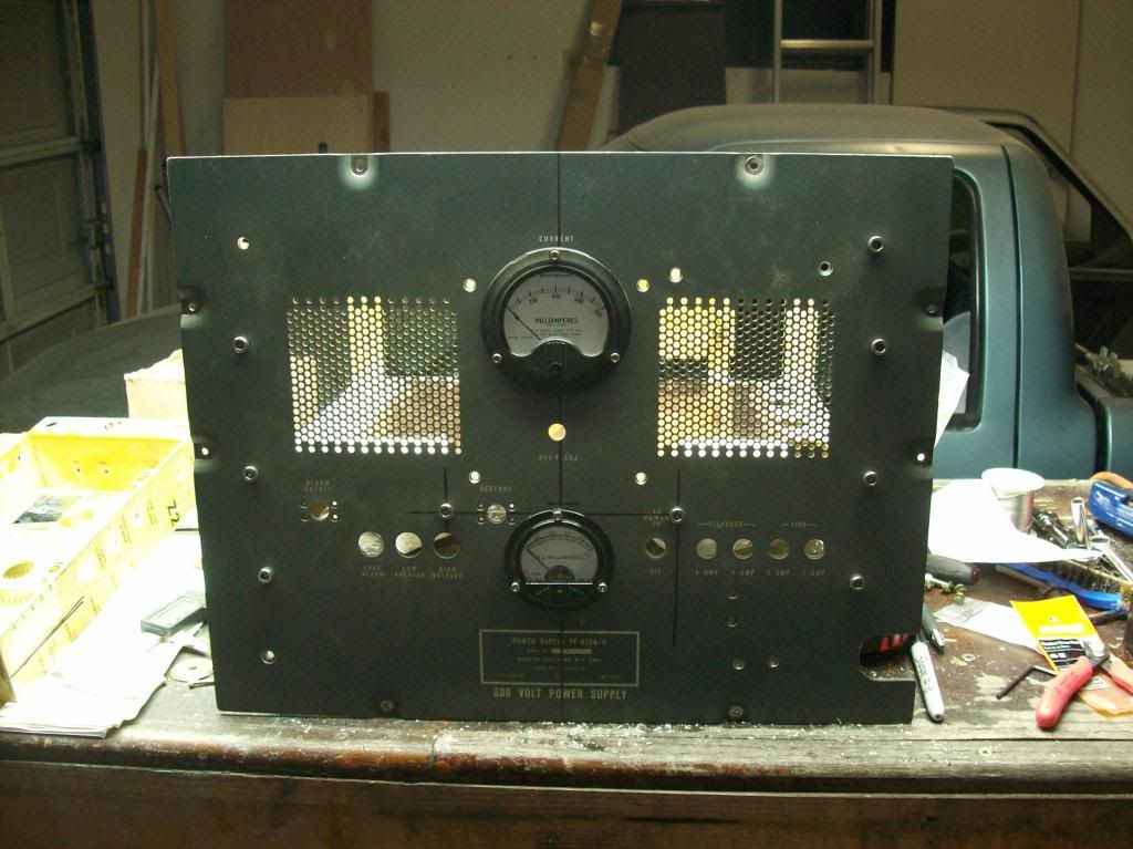
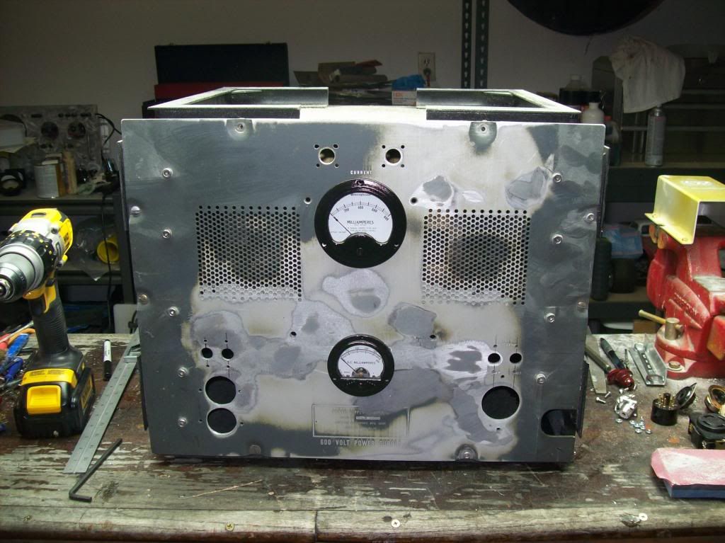
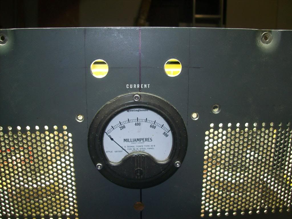
Started laying out where the connectors go on the front panel, circled the holes that were unnecessary to be welded up:
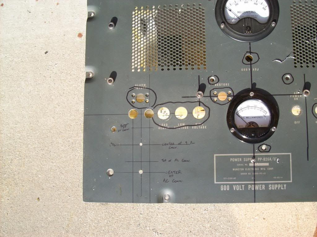
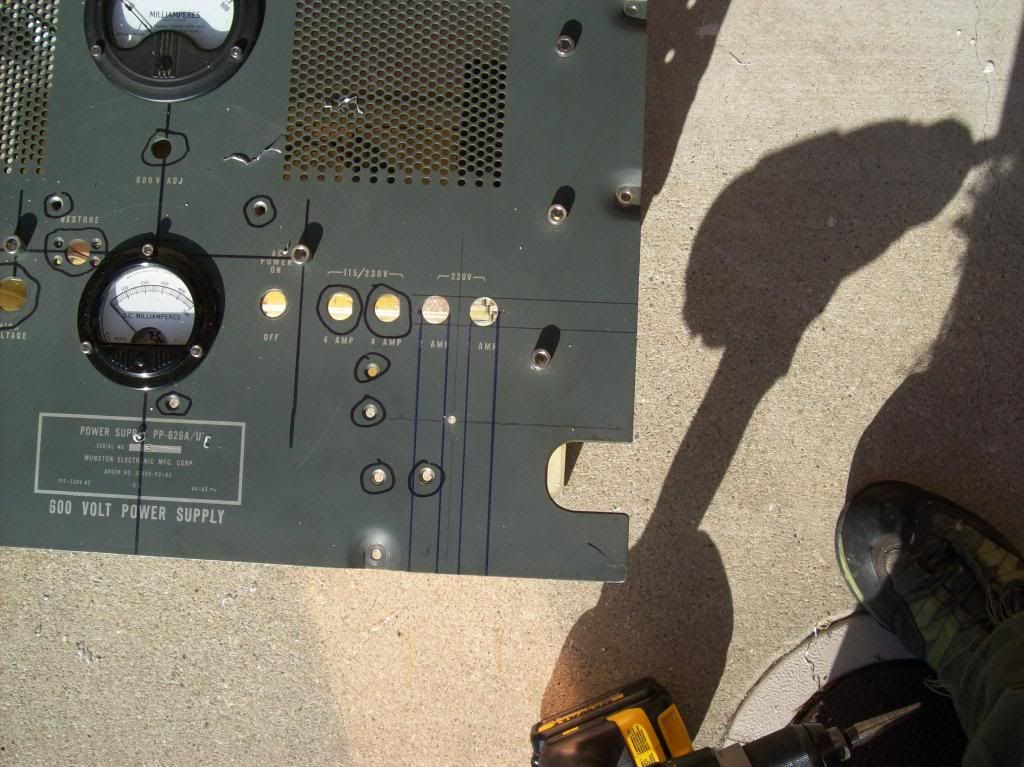
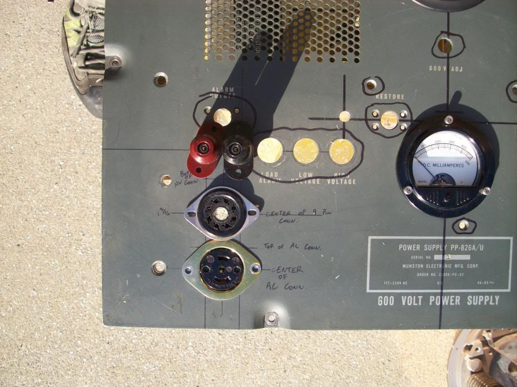
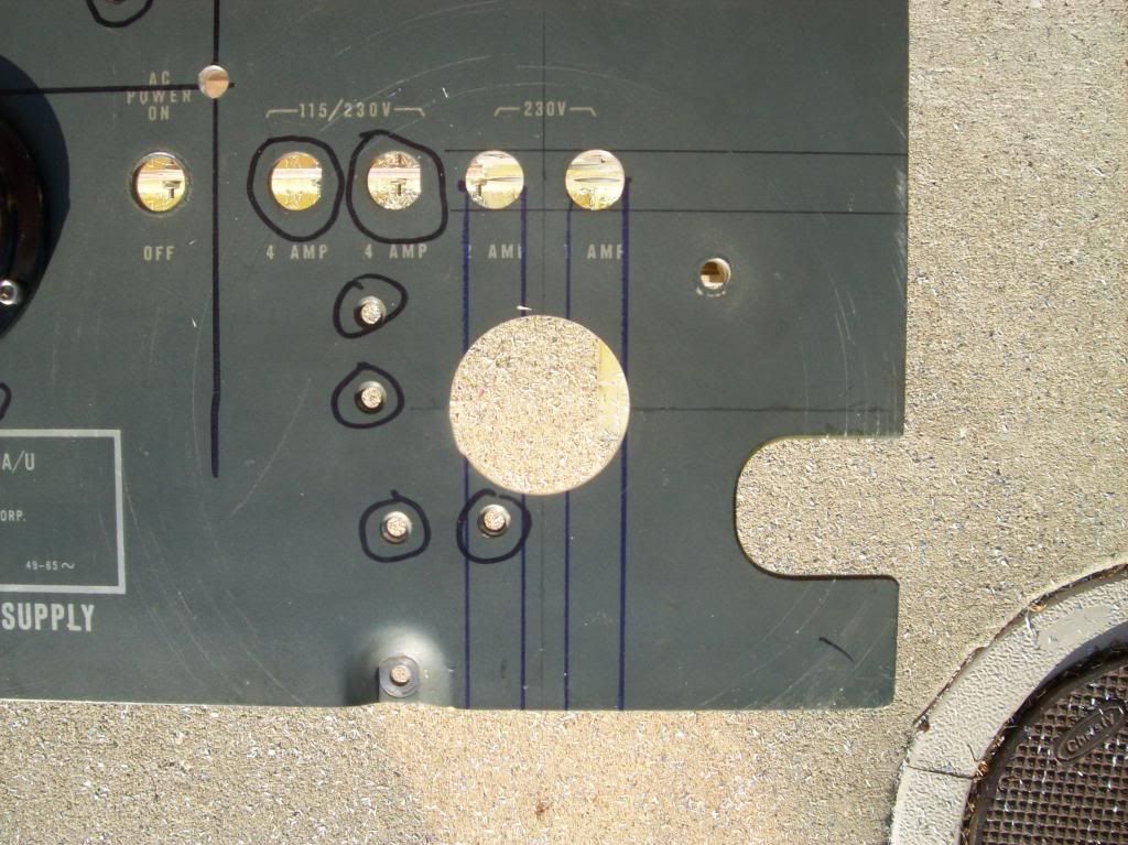
Ground down to bare metal where the holes need to be welded:
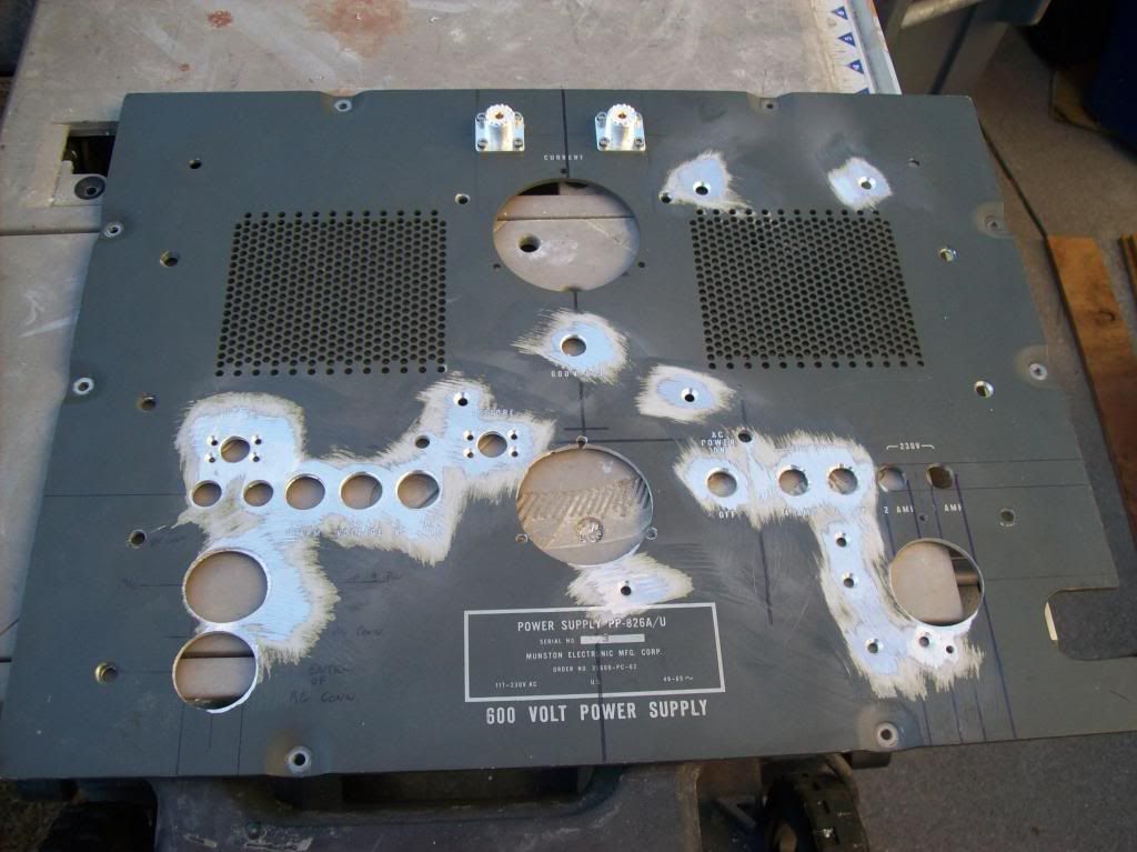
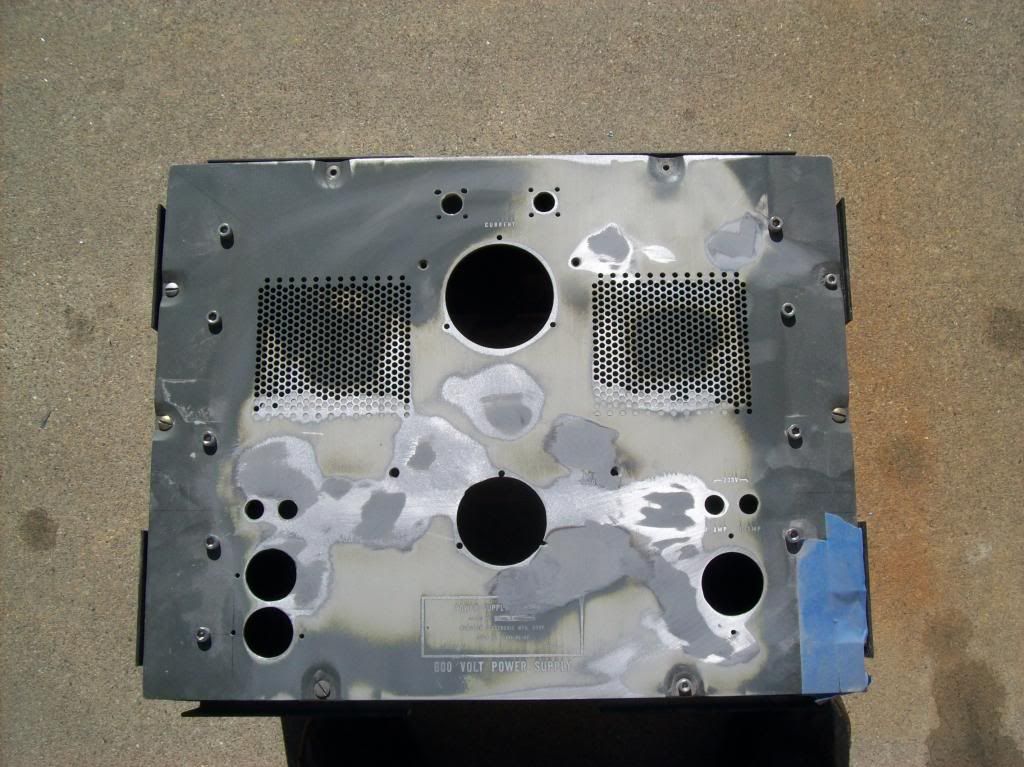
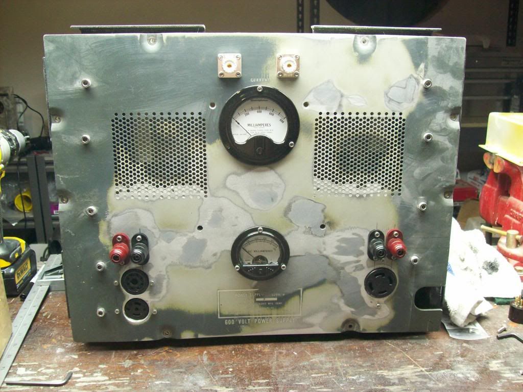
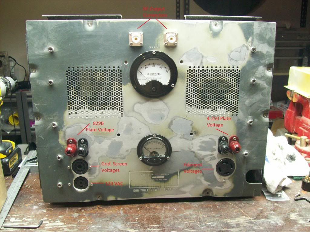
Had the holes welded. There were still some imperfections in the panel left from the welding, and the panel wardped slightly from the heat, so I had to do some filler work. I used JB Weld. I prefer JB Weld over body filler for a couple reasons: its waterproof, its more durable, and its self leveling. (it requires a longer cure time though)
The panel with filler on it:
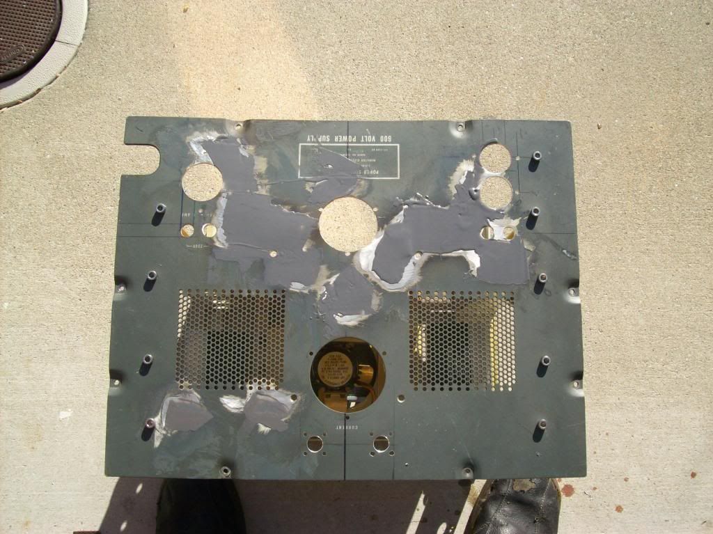
The panel sanded:
Leave a comment:
-
-
Yes the 2.4 Mc was without any gradient rings, just free resonance. I figure when I add the capacitance it will bring it down somewhat, but I'm not sure to where yet. I'm going back to the lab in a little less than a month and will let you know the results.Originally posted by dR-Green View PostWas that without any gradient rings or anything? Eric's coil design had a shorter secondary wire length than standard which would make the coil's "free" frequency somewhat higher than the design frequency, because the condenser is supposed to tune it back down. Assuming you also used the 20 turn secondary calculations, my first secondary with one gradient ring had a resonant frequency about 1.12 times F (yours is 1.3). I'm not sure if I ever measured it without the gradient ring so I don't know how much higher the frequency would be without it, but it's something to keep in mind if the test setup was as pictured. Also the wire looks wound pretty tight, out of interest I looked it up earlier and found that the wire will be approx 97% the calculated length if it becomes an octagon.
I had considered that the 'octagon' shape would make the wire length shorter, but I never bothered to figure out by how much. I'm glad I know now! I didn't realize Eric's equations were designed to make the frequency a little bit higher so the capacitance could bring it back down. Thanks for letting me know! I'll let you know anything else I find. I'm going to the lab in a little less than a month to fire up the coils with the now working TCS.
Leave a comment:
-
Excellent work John.
Was that without any gradient rings or anything? Eric's coil design had a shorter secondary wire length than standard which would make the coil's "free" frequency somewhat higher than the design frequency, because the condenser is supposed to tune it back down. Assuming you also used the 20 turn secondary calculations, my first secondary with one gradient ring had a resonant frequency about 1.12 times F (yours is 1.3). I'm not sure if I ever measured it without the gradient ring so I don't know how much higher the frequency would be without it, but it's something to keep in mind if the test setup was as pictured. Also the wire looks wound pretty tight, out of interest I looked it up earlier and found that the wire will be approx 97% the calculated length if it becomes an octagon.Originally posted by jpolakow View PostThe resonant frequency of the coils turned out to be 2.4 Mc, slightly above the designed value of 1.8 Mc. I’m not sure what caused the discrepancy yet, but I will investigate on the next visit.
I also have progress to report. The 17 turns Colorado Springs secondary configuration is being replicated as closely as possible, so in order to translate calculated wire spacings into the real world as acurately as possible by hand I arranged a series of lines on illustration/DTP software to represent the location of each turn and printed it out at 100% scale. This gives a paper template to work from, which is then stuck on to the PVC conduit and sliced with a knife. This then gives an edge to work against with a small file(s) to make the grooves.
The CS primary and secondary are closely coupled and so this scales down to VERY close coupling, calculated at just over 1mm space between the conductors, which may or may not be a problem. Also because the primary and secondary copper masses are matched it requires a relatively thick primary conductor, which makes replicating the original primary groove spacing physically impossible because one turn would be inside the other, however the original spacing between each turn of the primary conductor itself has been reproduced. So being an experimental coil provisions are made with grooves for 15 primary turns with constant spacing in order to adjust the coupling, and some extra length of PVC conduit is left at the top of the frame to allow use of a condenser ring if need be.


The end result will look something like this, but I haven't decided where the inner ring will end up yet.

Leave a comment:
-
As to where it stands right now, I am working on completing the transmitter/modulator (which drives the Tesla Coils). It will probably take a month or two before I am able to finish it. I am taking my time, and making sure everything is being done methodically and correctly. There's no room for short circuits when working with 5 KV! After the transmitter is completed, then there are a few power supplies I have to complete that put out the various electrode voltages for the vacuum tubes. And also I need to make a meter panel that displays all the important voltages and currents going on in the transformer. Overall I expect to be done with the first phase of this project within about 6 months. Then there are more "cool" things that can be done afterwards.
I probably won't really be answering many questions regarding the build, I am focusing my time on actually designing and building the equipment. However I will give periodic updates to my progress. Sometime within the next month or so I plan to go back to the lab where we will do a test run of the coils, and I will try to take more pictures at that time. Progress is slow but steady.
Also for those that have seen Techzombie's recent video, I had nothing to do with it and regret that it was made. I feel I was misrepresented in the video. About a year ago I decided I wanted to do a recreation of Eric's CIG. I started gathering parts and building some of the lower voltage power supplies. I started making significant progress about 6 months ago, and the pieces started to fall into place. The coil calculations were done, the coil forms were engineered and built, and the HV power supplies started to come together. In the video it seemed to be claimed that I was "struggling" to finish the CIG, and that I am being used by this person or that person. To be clear, the only person I have really been making this piece of equipment for is myself and Eric. There is no hidden agenda or anything like that. It displays what part of us at EPD Labs have been working on. Yes it is a struggle sometimes (HV parts and vintage radio parts are expensive!), and sometimes there are design roadblocks, but that is to be expected in any project. I will continue this project to completion, even if it ends up taking longer than I thought. I have learned a significant amount in this undertaking, and it has been enjoyable. For anyone that wants to truly learn the principles that Eric is presenting, the only way to do that is to put it into actual practice.
(more pictures and updates to come shortly)
Leave a comment:
-
More of transmitter build
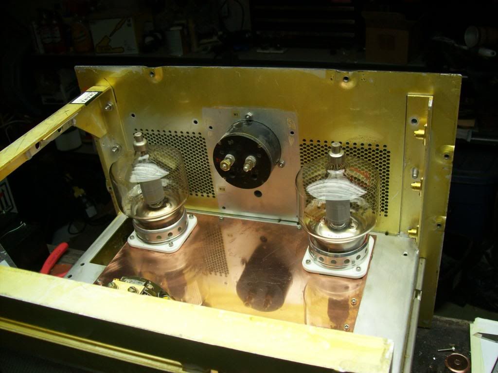
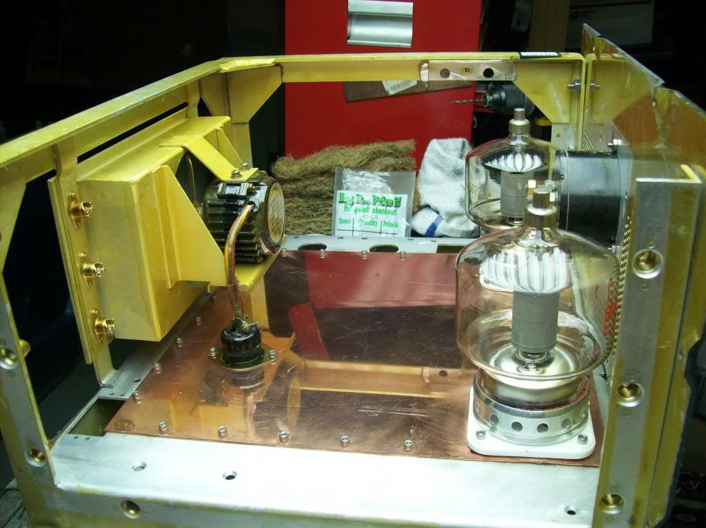
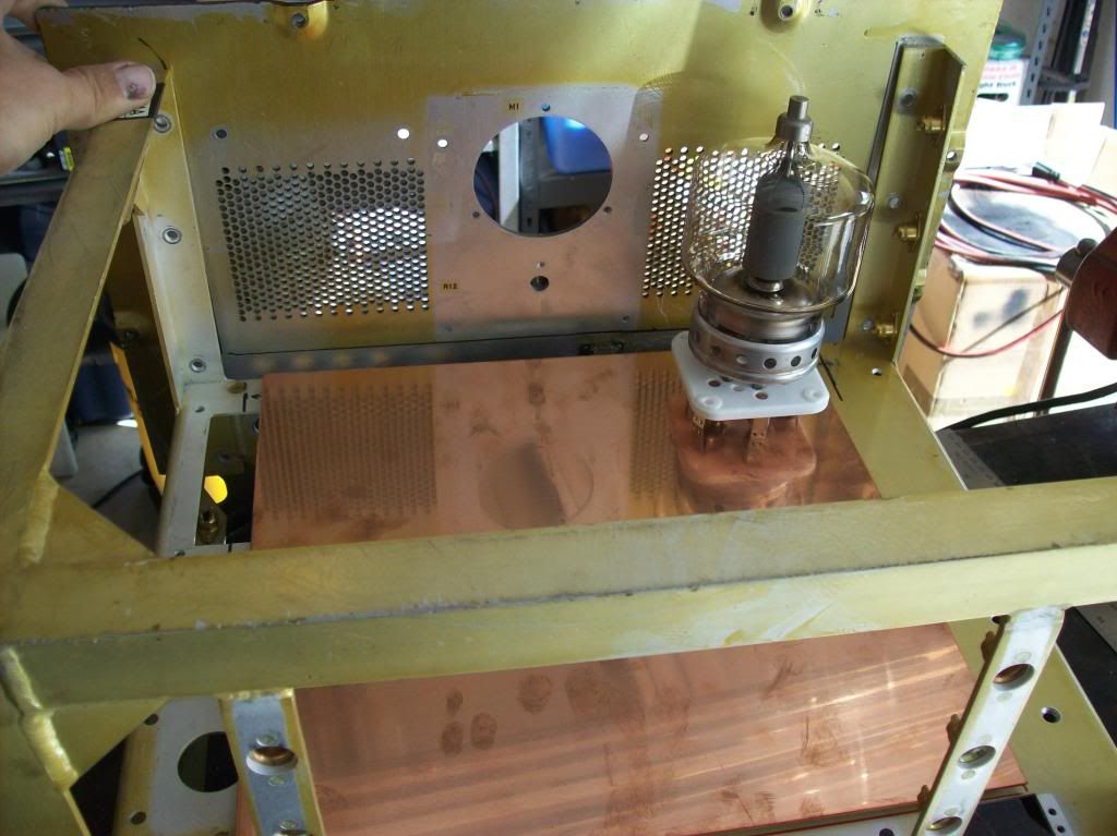
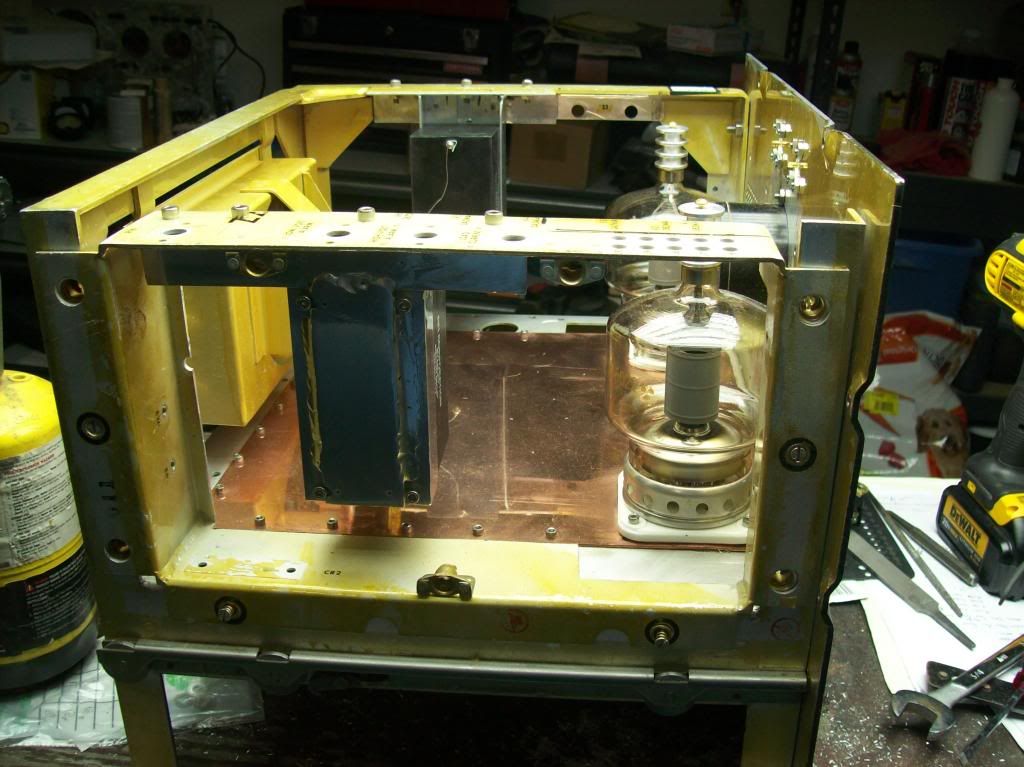
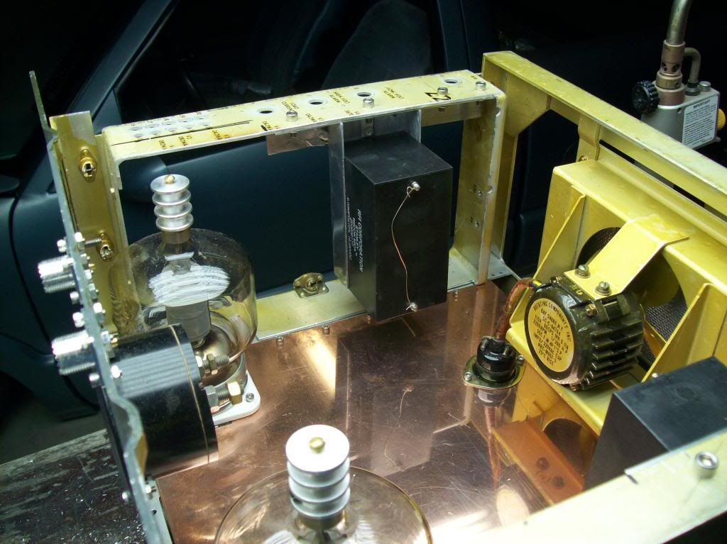
Tubes installed:
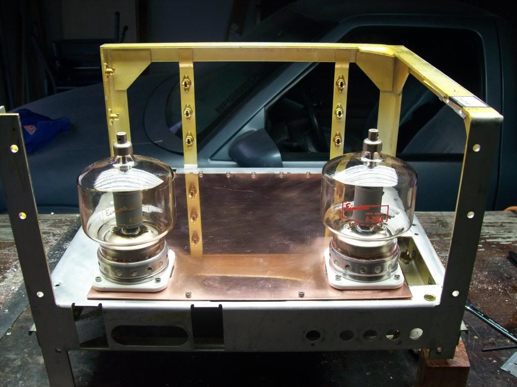
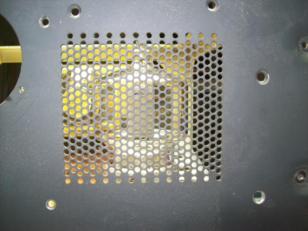
The 4-250's are visible through the screen:
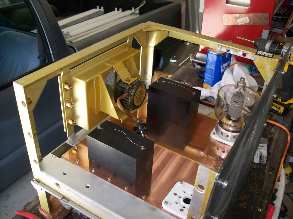
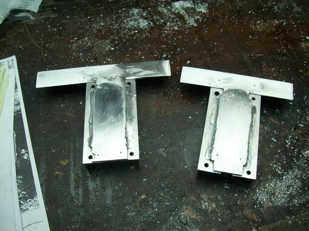
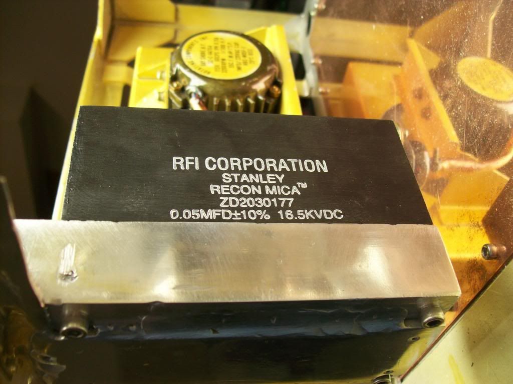
The black boxes are the output coupling capacitors, to keep the 5 KVDC plate voltage off the Tesla coils. They are rated at 16.5 KV and weren’t cheap!
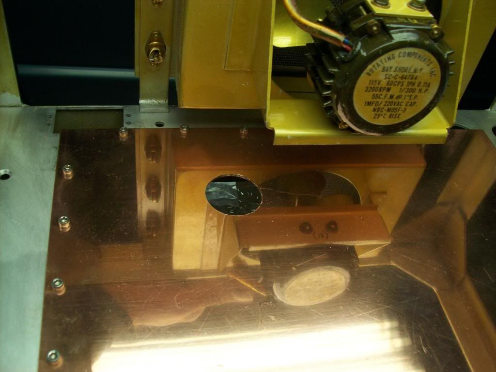
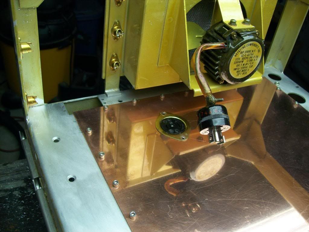
Mounting the fan connector:
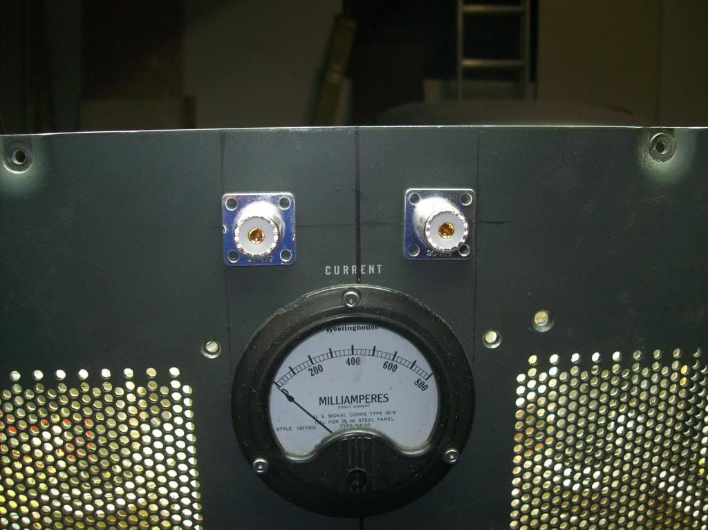
Two meters on the front panel installed:
Leave a comment:
-
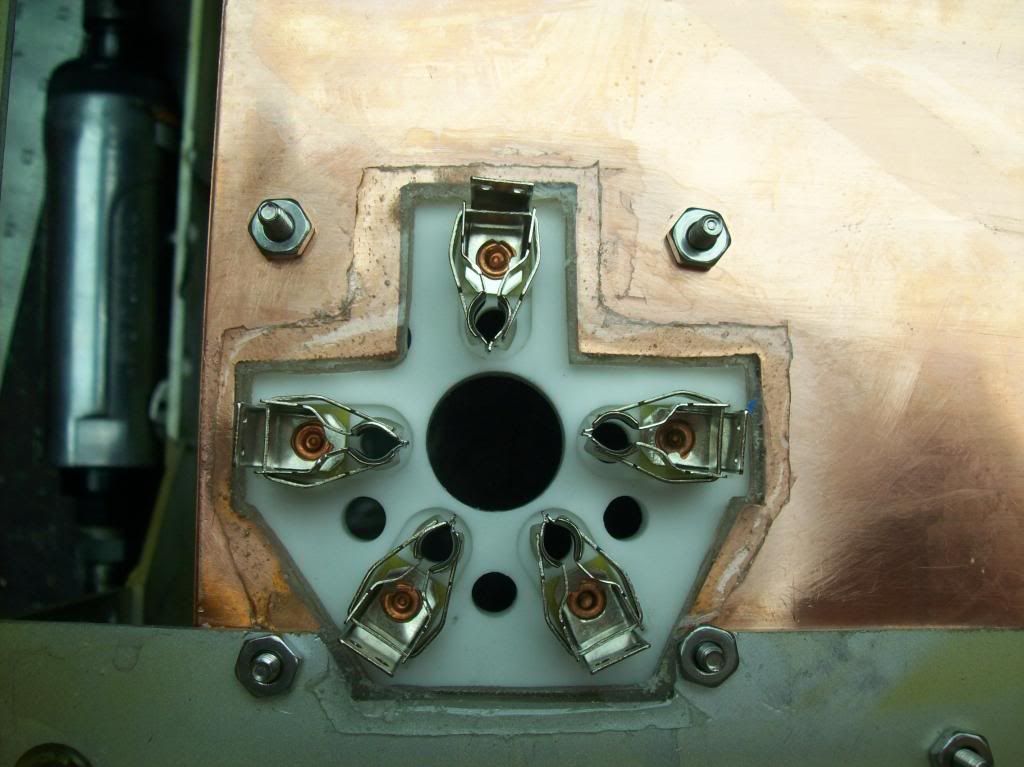
I decided it would be good to insulate the ground plane from the socket terminals because they would be in close proximity.The max voltage these terminals will see is around 800 V (for the screen voltage), and -500 V (for the grids). The 5 KV plate voltage goes on the top of the tube.
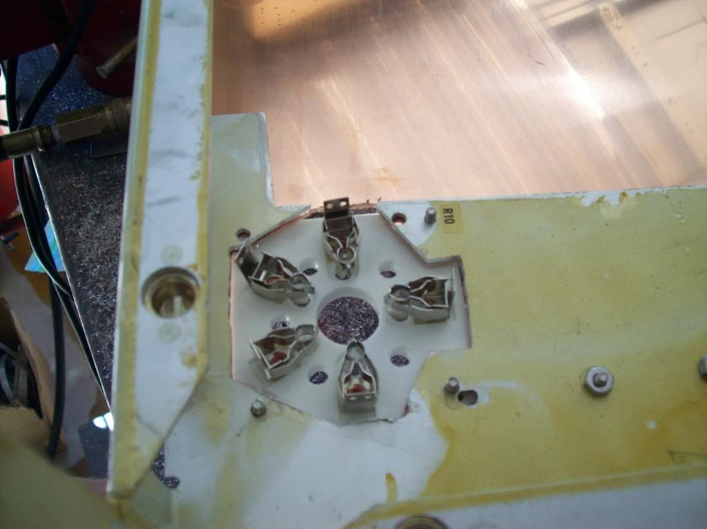
So I masked off the copper and poured some epoxy on both sides of the ground plane:
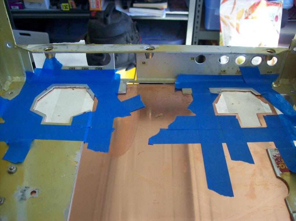
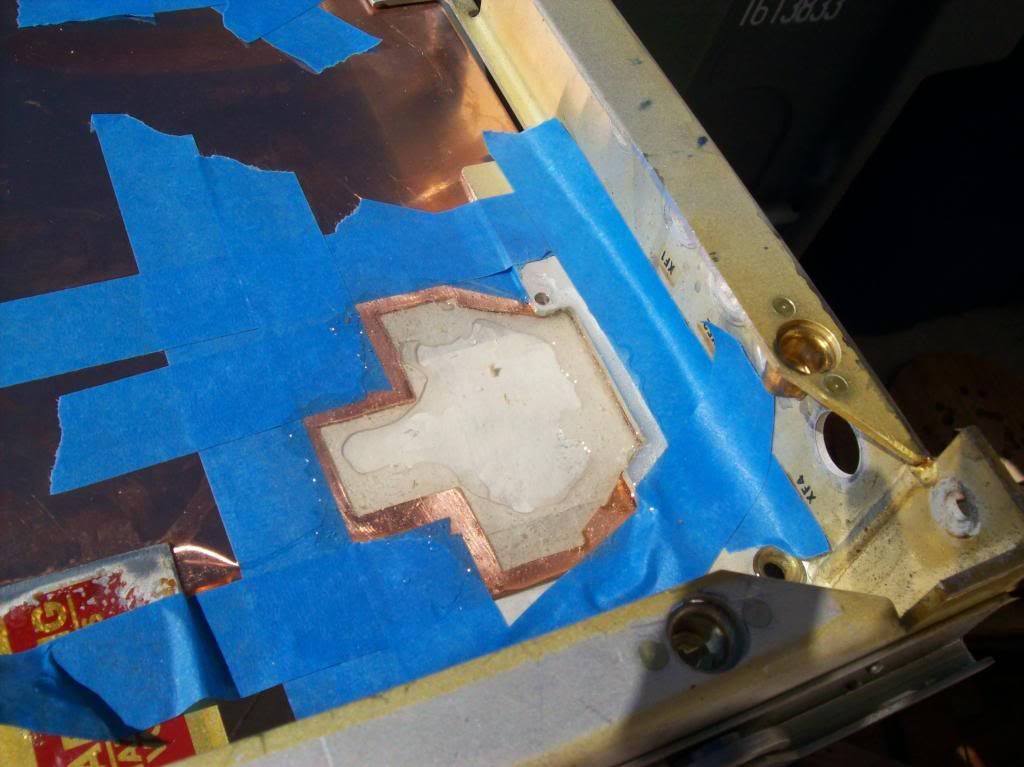
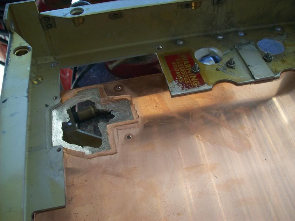
The epoxy was then filed down until it was just an edge over the copper:
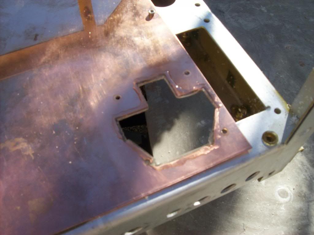
Sockets fit perfectly:
Leave a comment:
-
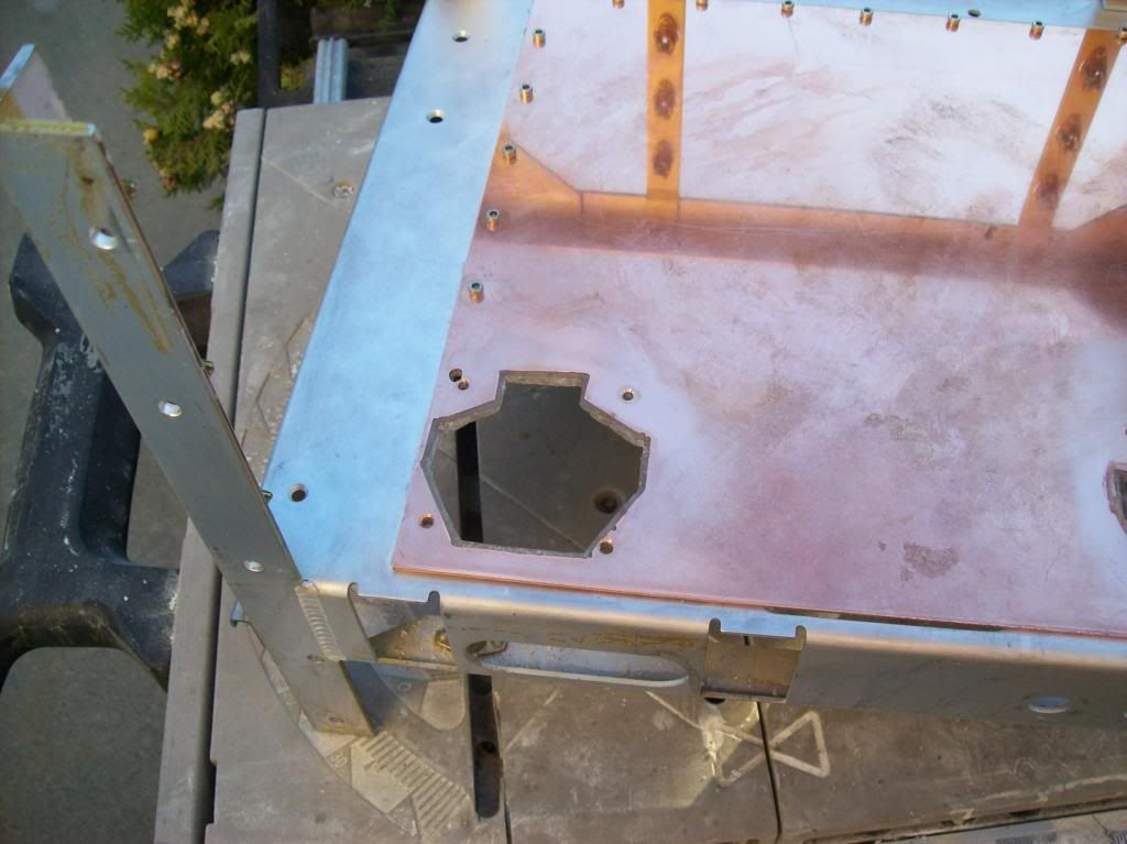
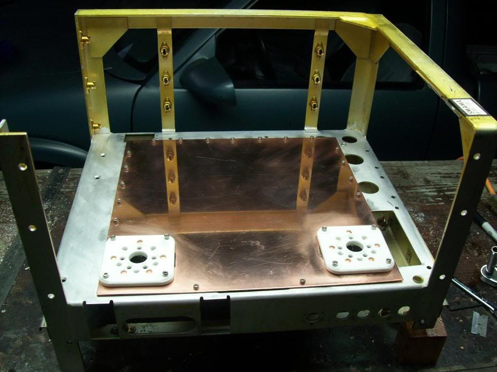
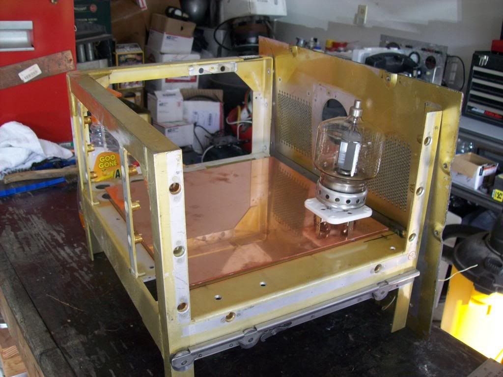
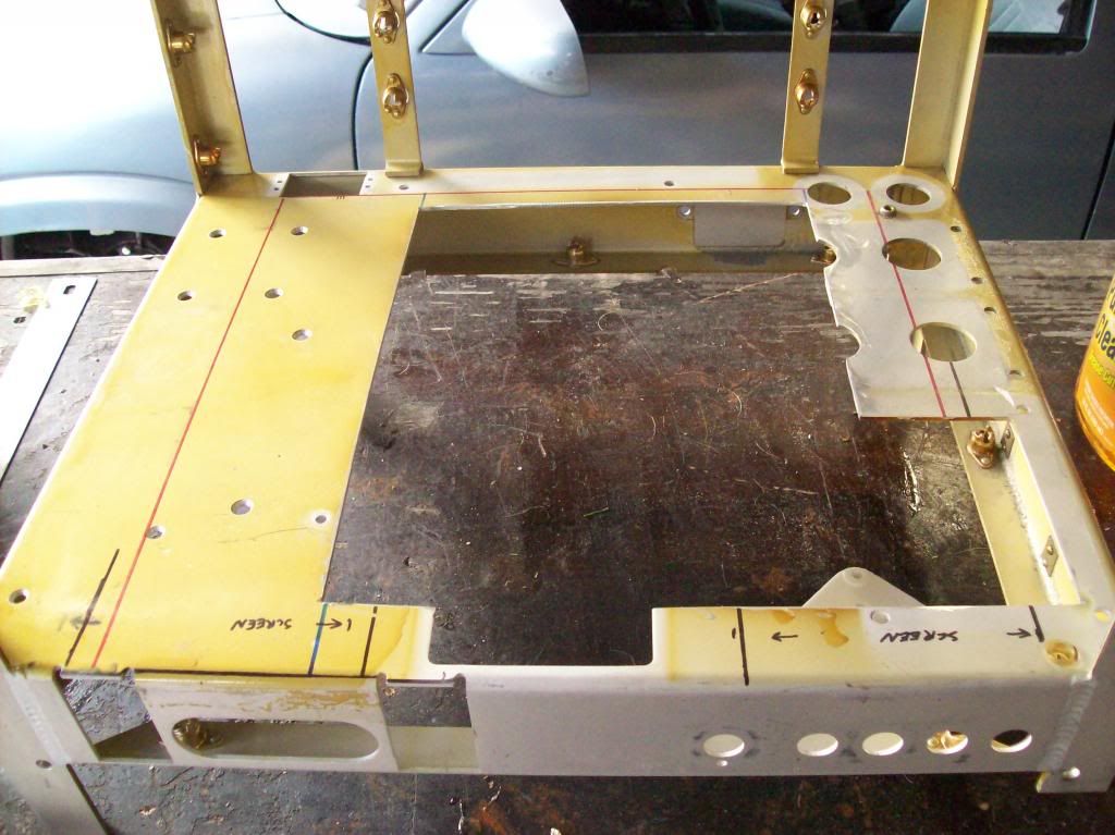
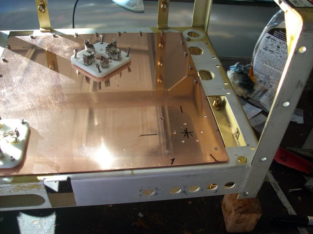
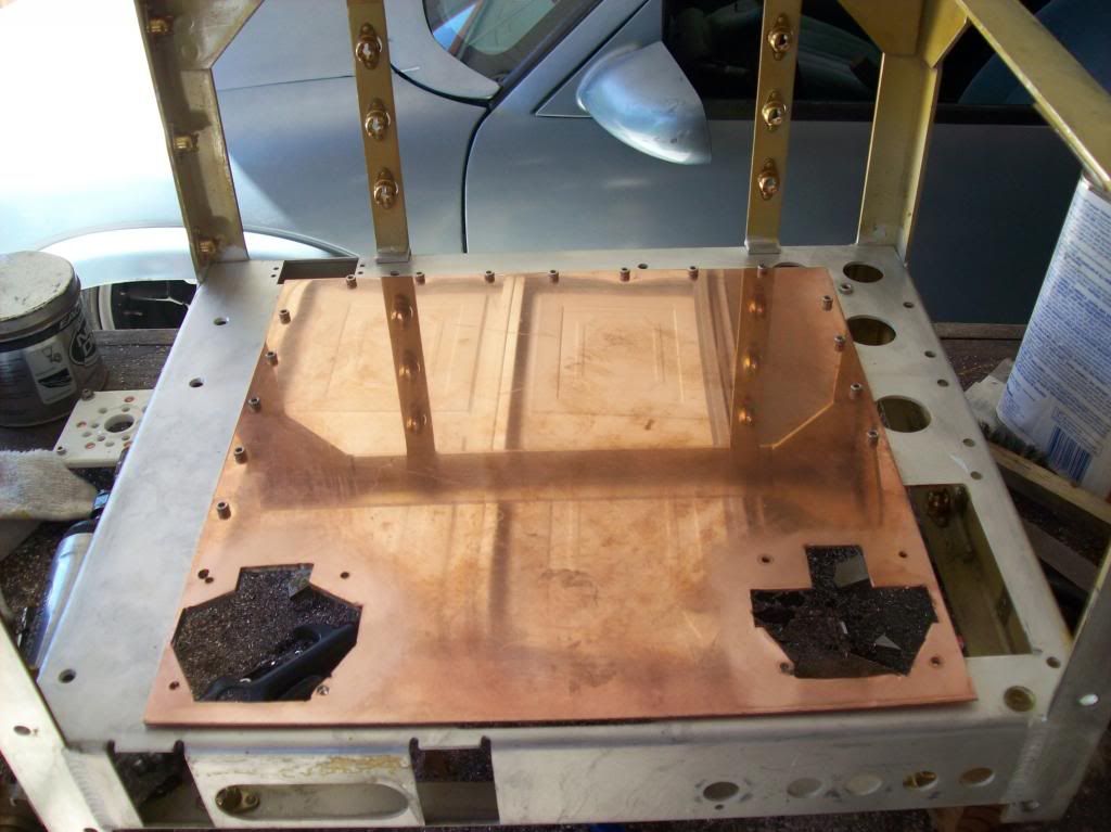
Now for the transmitter construction I have been working on. Previously I had stripped the power supply chassis bare to repurpose it as a transmitter. The first thing to do was to get the big components in, the 4-250’s first.
A copper ground plane was test fitted, and then installed:
Marking the cutouts to be made:
Ground plane attached, marking the cutouts for the tube sockets:
Cutouts made:
Leave a comment:
Leave a comment: