Recent trip to lab
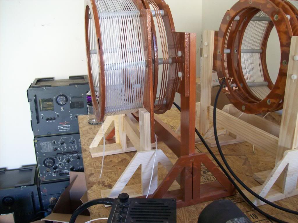
The plan was to do a test run of the coils. Unfortunately the CIG gods had other plans for us. The coils were to be driven by a TCS WW2 era military transmitter.
Eric had previously acquired two of these transmitters, and both were supposedly operational. Neither transmitter turned out to be functioning when we attempted to fire them up. The transmitters receive their HV supply from a motor/generator unit called a dynamotor, which in turn is run off a 12 volt battery. Unfortunately the dynamotor was mis-wired, so it wasn’t providing filament voltage or plate voltage to the transmitter. After going through the dynamotor wiring checked against the schematics we were able to correct the mistakes. (Tracking down wiring problems in big bundles of wire can be very tedious)
A second attempt was made to fire up the transmitter and this time smoke started coming out of the power supply cable where it connected to the transmitter. It is a multi-pin connector, and some of the wires were connected to the wrong pins. So all new cables were made with new wire, a very time consuming task. There were around 15 pins on each end of the cable, and 2 cables to be made. So around 60 solder connections to be done, and they were difficult to solder! After that to avoid further problems we went through the transmitters to check for problems. More issues were encountered.
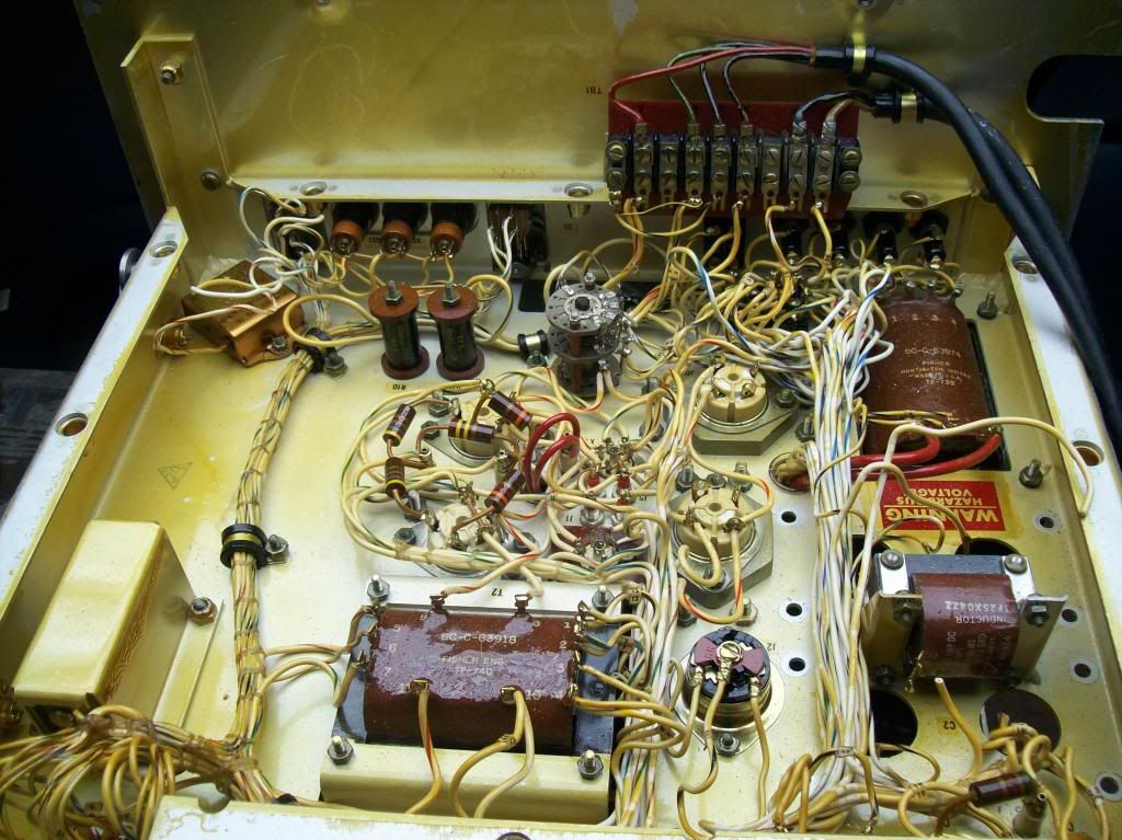
A ham had previously been inside the transmitter and attempted some ill advised modifications. After much checking against the schematics again we were able to isolate the modifications and reverse them to correct specs. Also we discovered some broken parts. One of the adjustable loading coils (tuning inductance) was broken; its ceramic core had shattered at some point.
After I had spent 5 days there, I had to return home to go to work. I spoke with Eric on the phone the following day and he was able to get the transmitter going, and tune the coils to resonance. The resonant frequency of the coils turned out to be 2.4 Mc, slightly above the designed value of 1.8 Mc. I’m not sure what caused the discrepancy yet, but I will investigate on the next visit.
It was a good exercise in troubleshooting though. Eric is absolutely brilliant in this area. He seems to have an uncanny intuition on where exactly to look when something is wrong. That kind of skill can only be gained through decades of experience, I was glad to have him there!
I should be going back in about a month to make another attempt at test firing the coils.
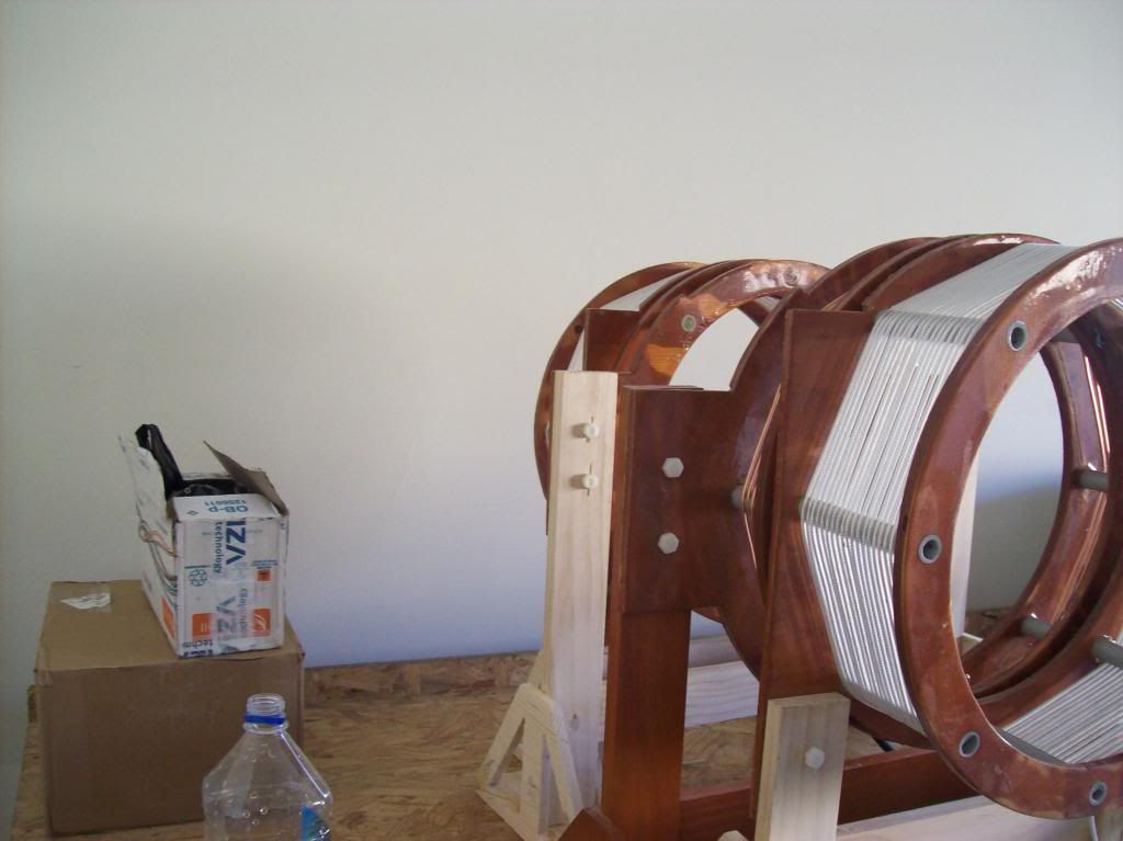
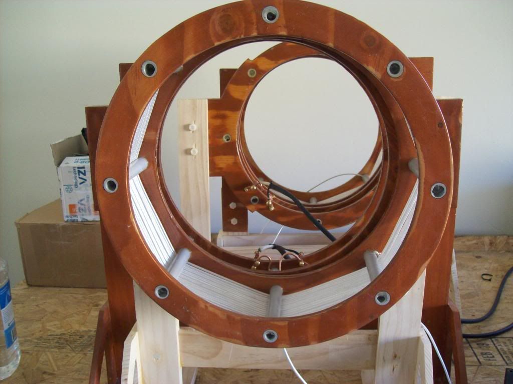
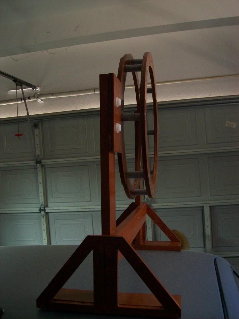
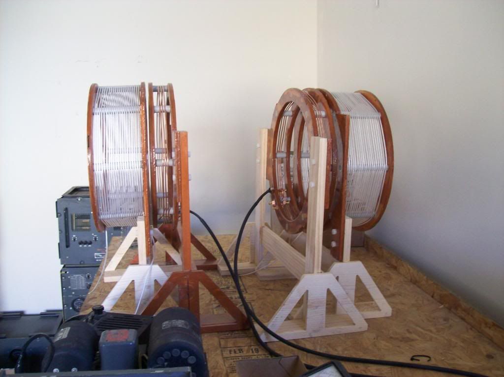
Here are some pictures of the coils mostly completed: (still need a gradient ring on the secondaries)
The coil stands for the primaries and secondaries were designed so they would exactly slip inside each other. You can see that in the pictures.
Announcement
Collapse
No announcement yet.
Eric Dollard
Collapse
This is a sticky topic.
X
X
-
Leave a comment:
-
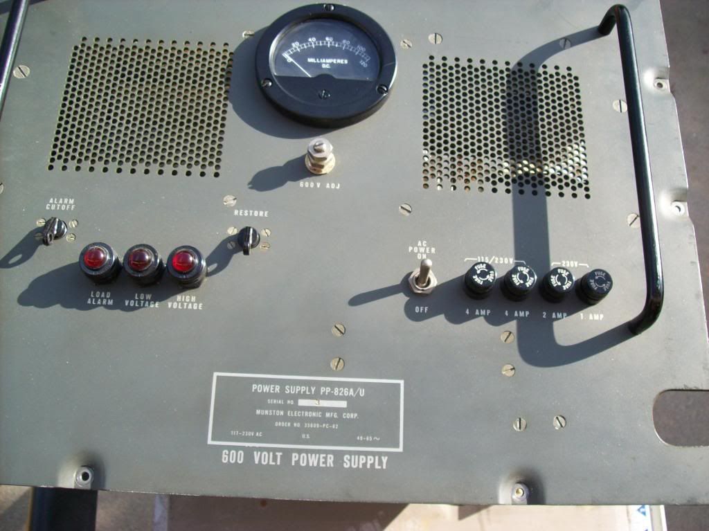
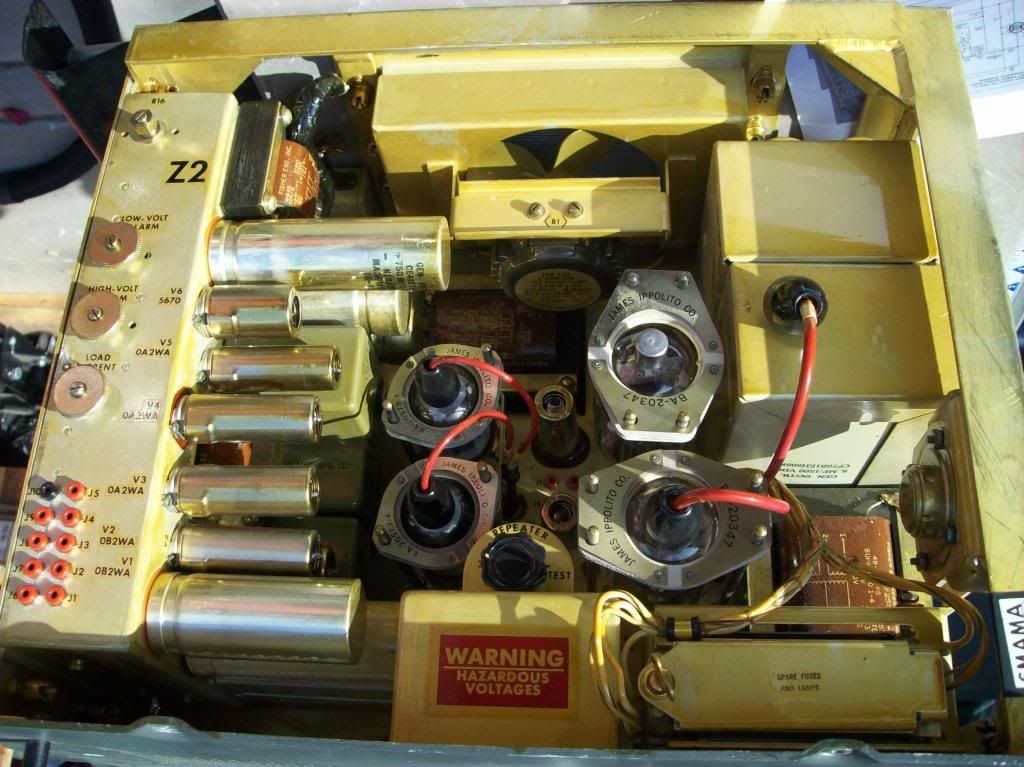
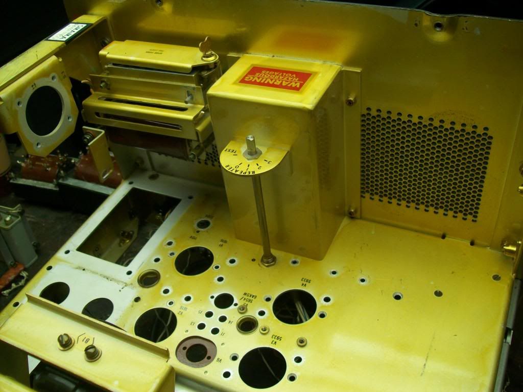
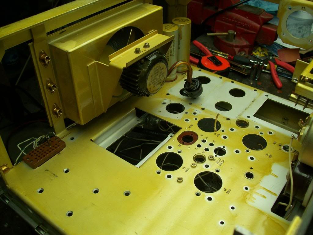
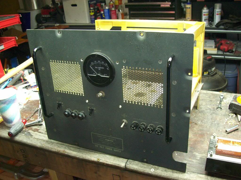
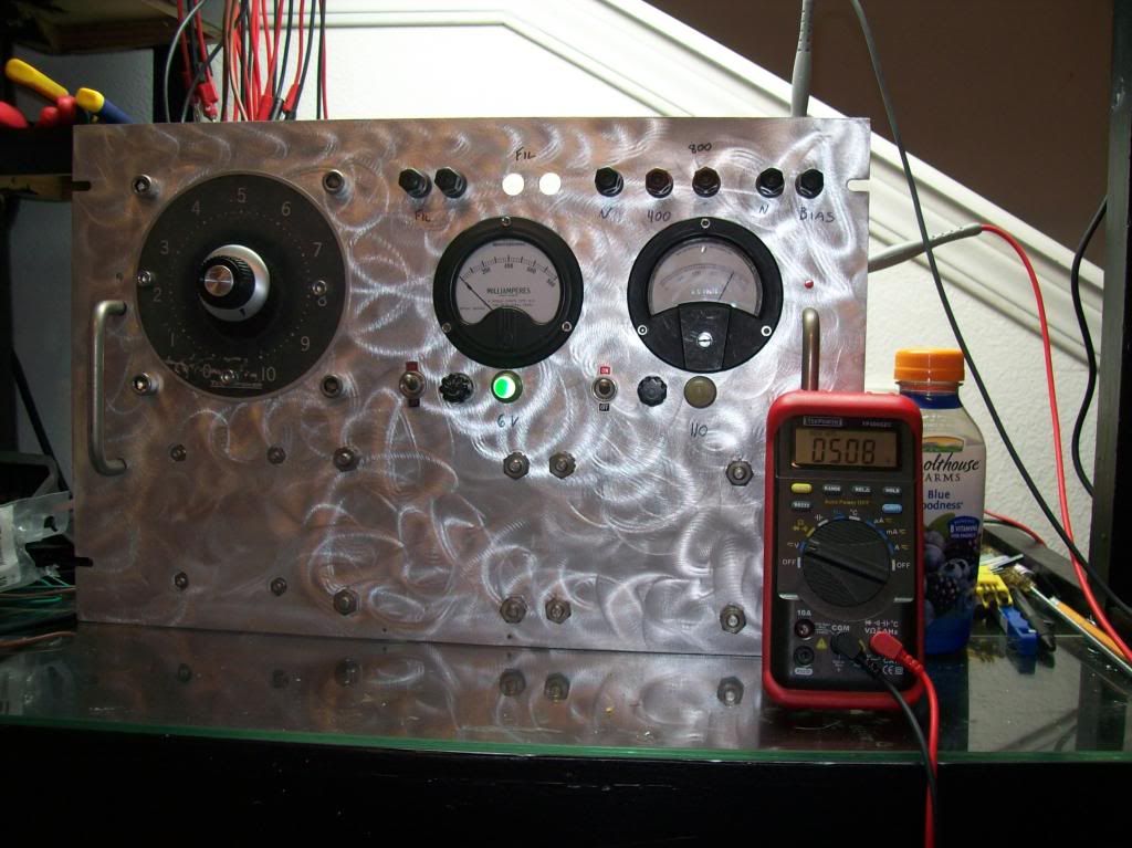
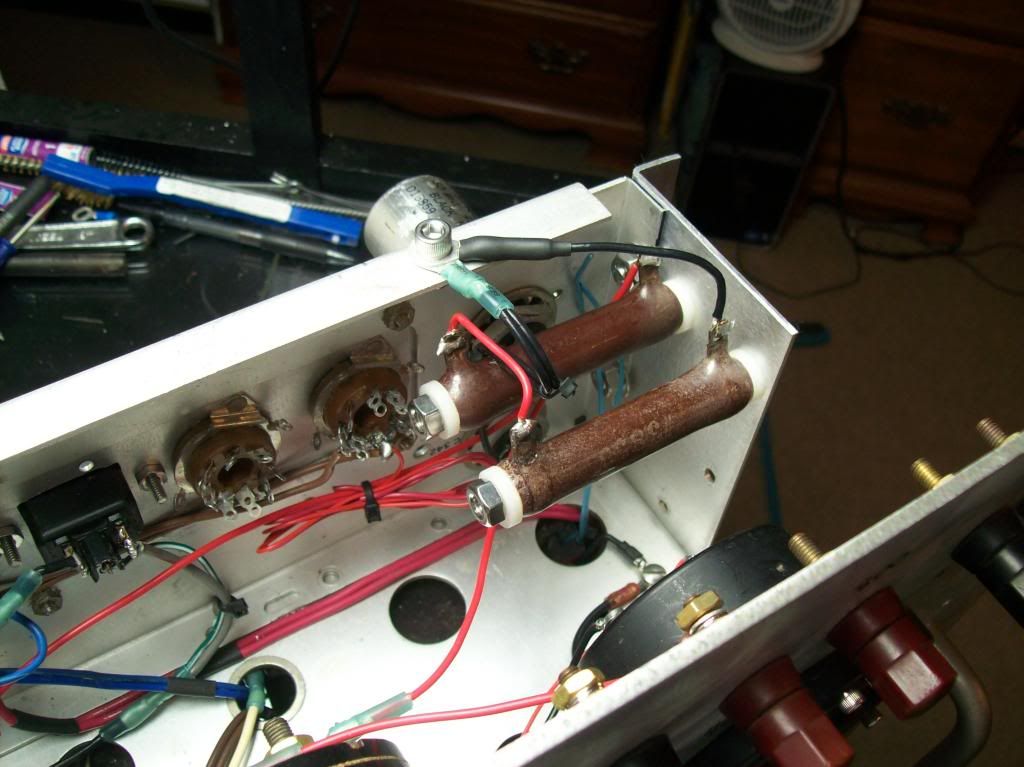
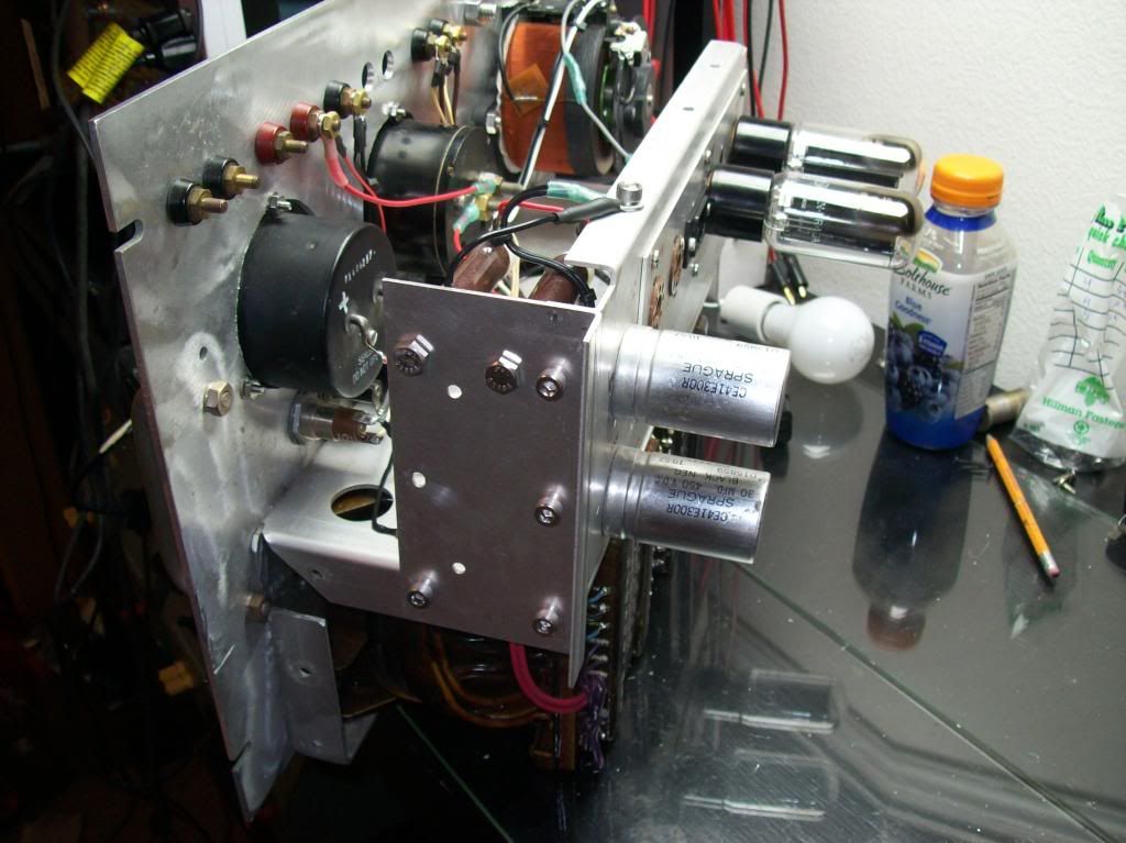
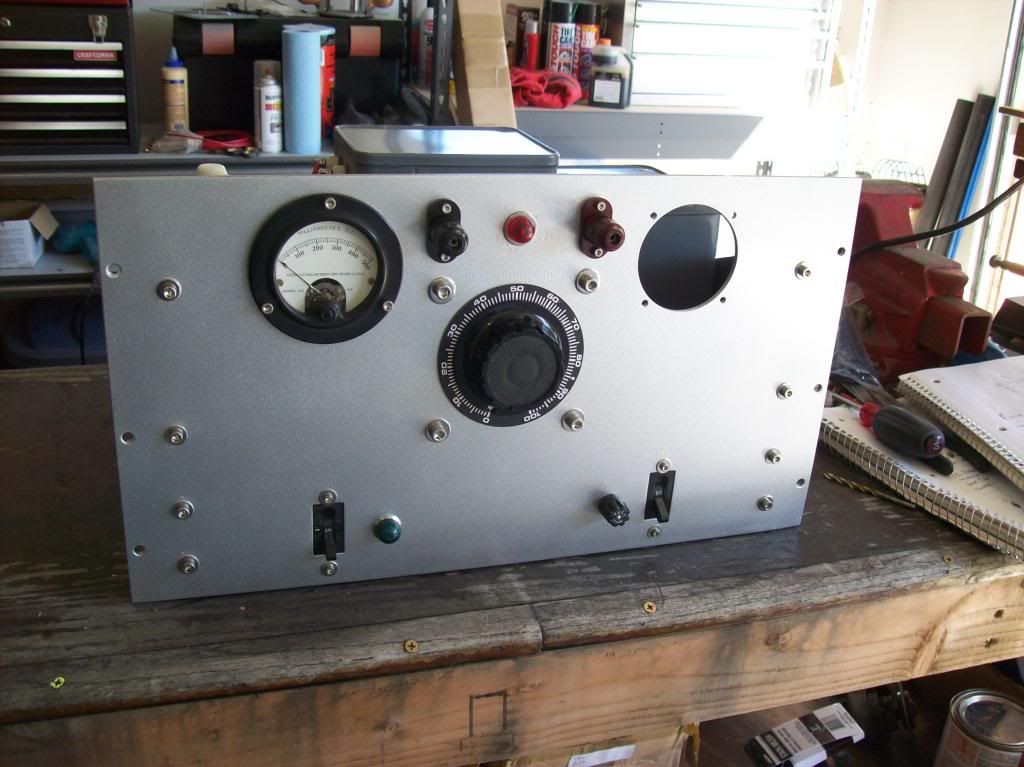
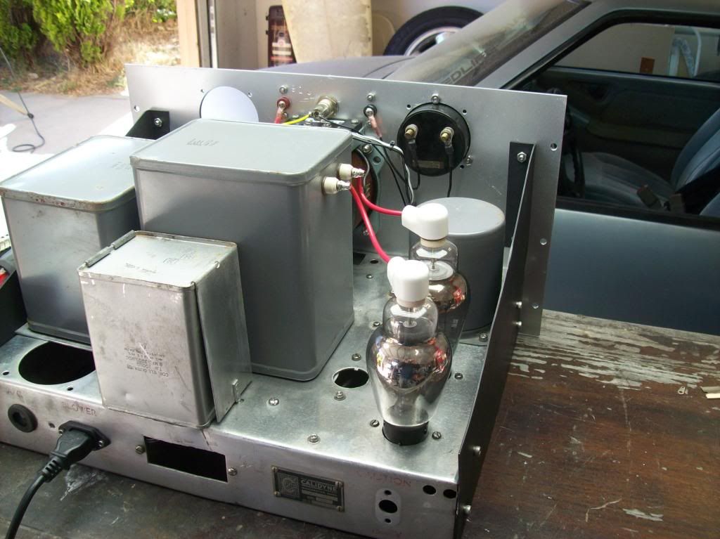
The transmitter itself for the CIG is being built on the chassis of an old 600 volt military power supply:
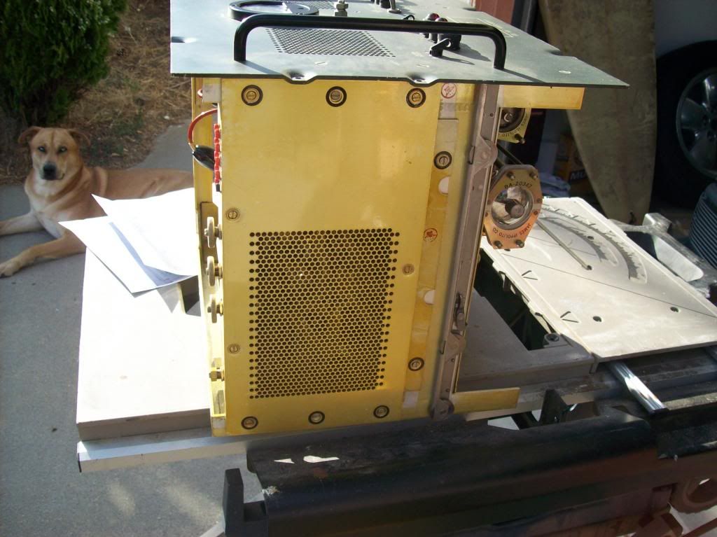
You can see my supervisor in the background here:
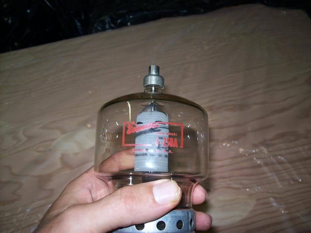
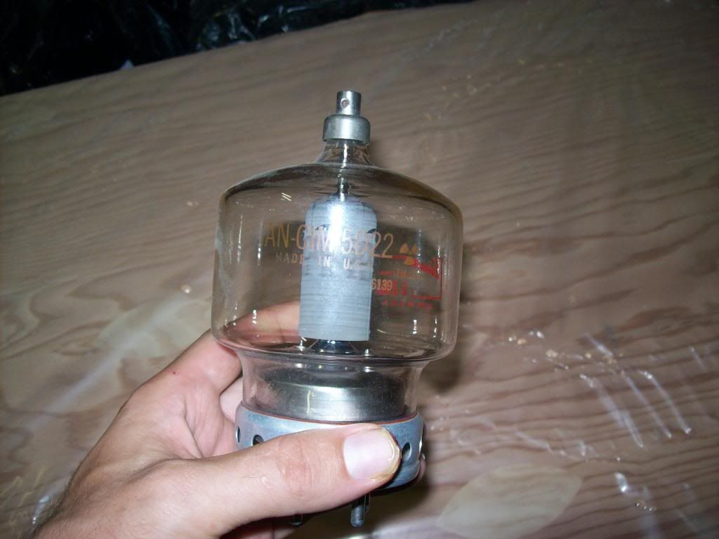
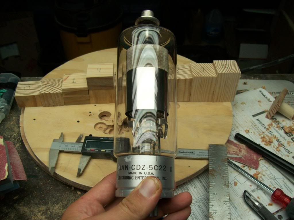
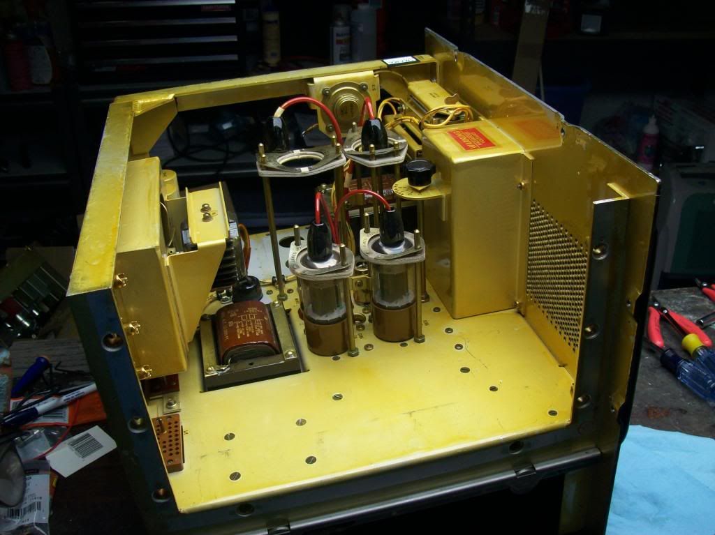
The power supply was in amazing shape, looking like it had never been used. All the tubes were brand new. I probably would have actually used the power supply because it was in such beautiful condition, but its current output wasn't enough for my purposes. I started dissasembling the PS to repurpose it as a chassis for the transmitter:
When the transmitter is complete you should be able to see the 4-250's glowing through the metal screens here:
Leave a comment:
-
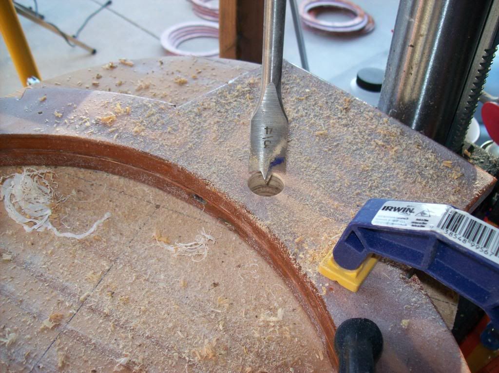
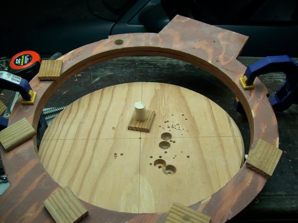
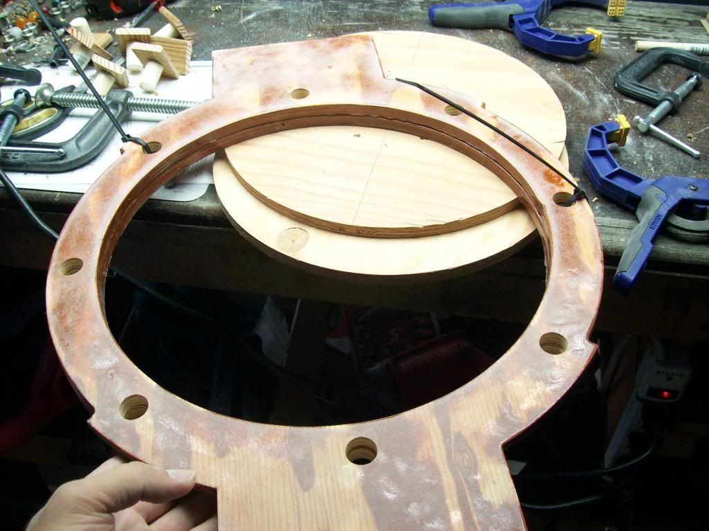
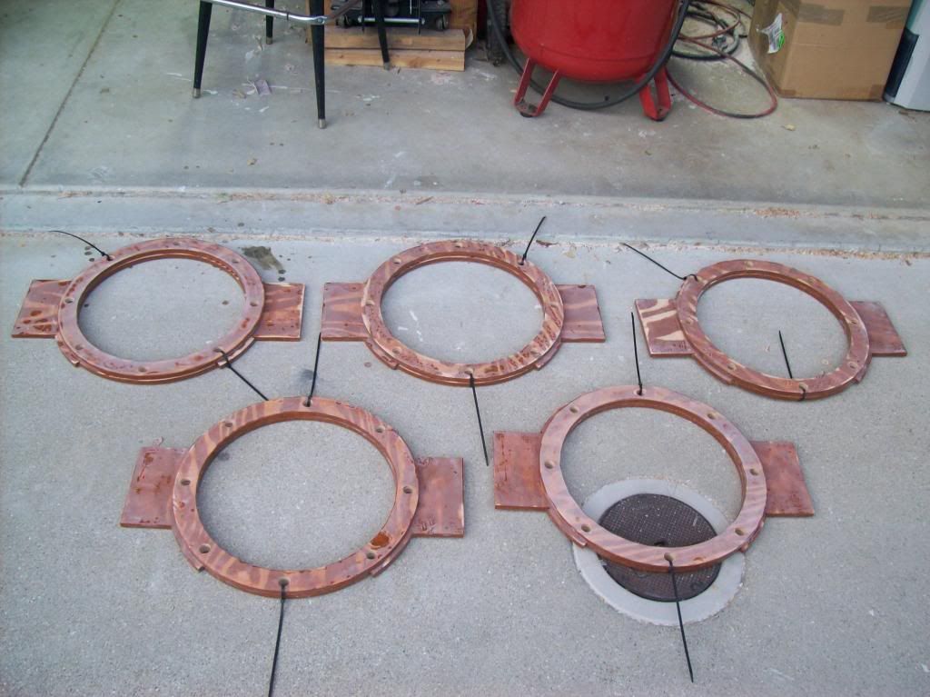
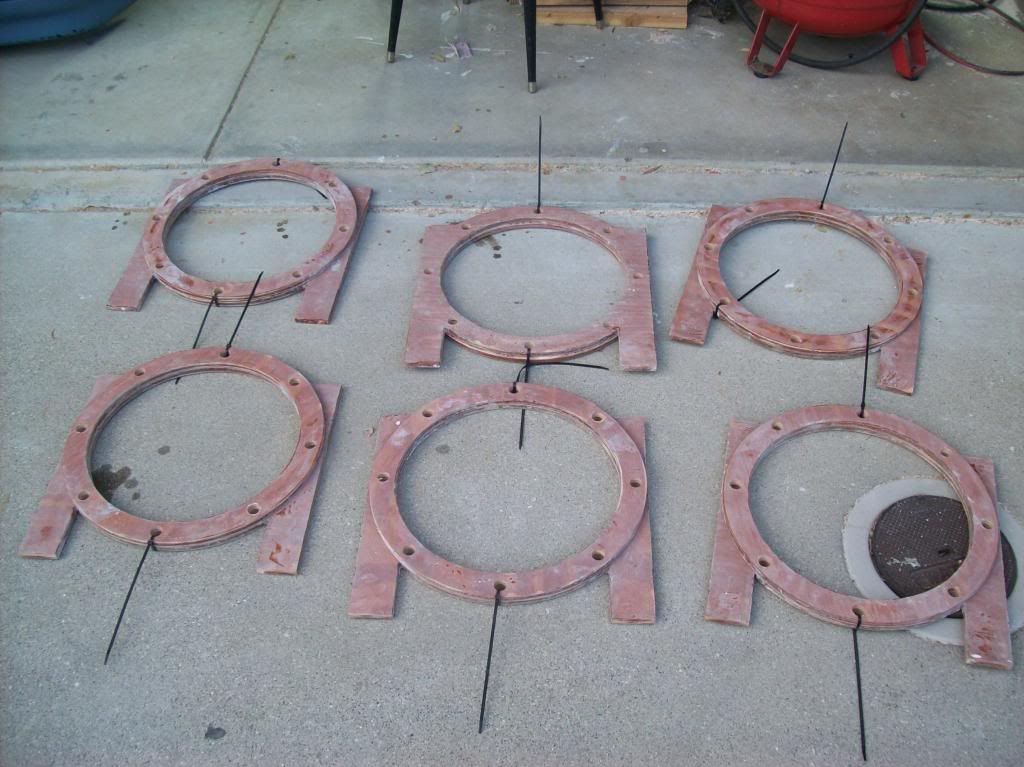
Coil Forms
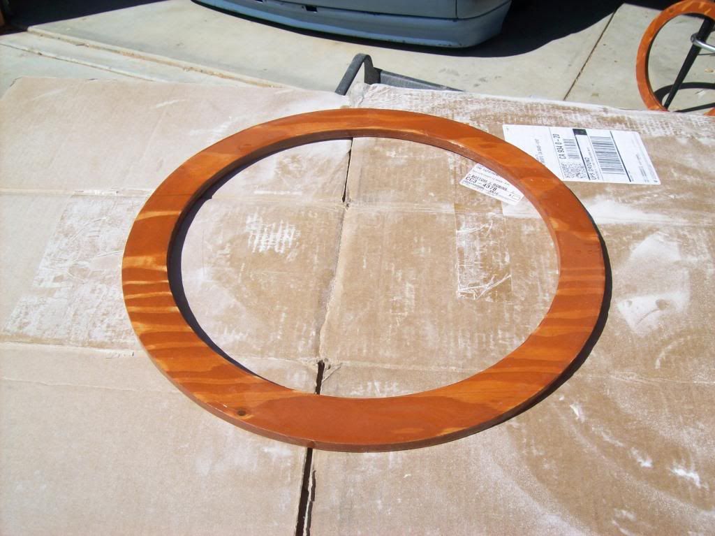
The Coil Forms were designed, and the wood bases built first. They were cut out of sheets of plywood with a router. Then baked to remove all moisture, and finally sealed with multiple coats of epoxy to increase the dielectric strength and also to equalize the dielectric gradient within the wood. Fiberglass tubes were notched where the conductors would lay.
Everything took a lot longer than it looks in the pictures. It took probably a couple months to design and build the coils.
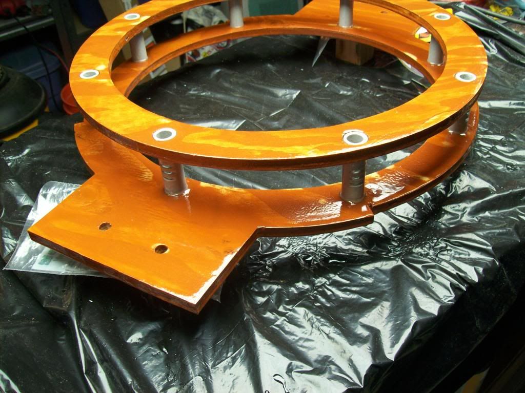
Primary bases finished:
Secondary bases finished:
A finished primary coil form:
Leave a comment:
-
Cosmic Induction Generator
Hey all,
Here's an update as to what I've been up to with the Cosmic Induction Generator (CIG)recreation. Its time for an update as to what I've been building.
As Aaron noted in his latest newsletter, I was at the lab recently with him and Eric. I had finished the coil forms, and brought the coil forms to the lab. I finished winding the coils and building the stands for the coils, and then we were going to do a test run of the coils and potentially make some sparks. Unfortunately fate didn't turn out that way, but progress was still made.
First, an overview of the CIG:
The CIG basically consists of an AM amplifier/transmitter which powers some Tesla coils. The transmitter consists of vacuum tubes providing the power amplification. Solid state components are used very minimally. The Tesla coils are in a unique configuration, two Tesla Transformers aimed at each other creating an extremely intense dielectric field in the middle of the two units. Also where a normal Tesla coil would be grounded to the earth in order to transmit, these coils will be referenced only to each other.
Between the two coils is where the magic happens. For the CIG, the objective is to put a bulb containing a gas conducive to plasma creation - in the middle of the intense dielectric field and see the "galaxy in a bulb". It is reported by Eric that inside the bulb the plasma takes on a life of its own, and the electricity has a memory, and displays intelligence. The primary objective of this project is to recreate that display.
The nice thing about the CIG though is that it is multipurpose. It can also be used to create "singing" arc discharges when modulated with an audio source. Also, all the coils(primaries, secondaries, extras) are being built on independent frames and stands, so they can be used in a different configuration than just pointing at each other. If spread apart and grounded they can be used to transmit and receive to each other.
CIG Components
The Induction Generator can be simplified to 3 distinct components: power supplies, the transmitter section, and the tesla coils.
Power Supplies
The power supplies are pretty basic DC linear supplies.
AM transmitter
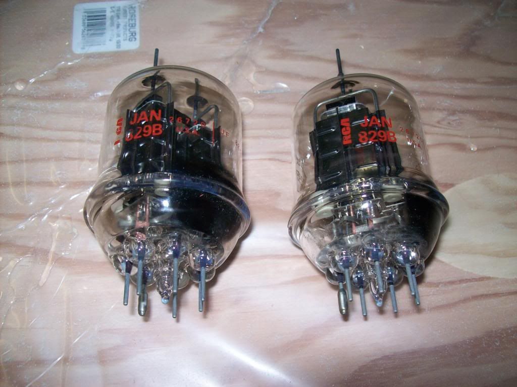
The transmitter will be Class C operation. This particular design consists of 829B driver tubes and 4-250 power tubes. The tubes will be in push-pull operation, driven at their maximum permissible values. The operating frequency is chosen to be 1.8 Mc, or 160 meters. The 829B tubes will be driven by a WW2 era VFO/Exciter/Transmitter called a TCS. The TCS puts out approximately 25 watts at an output impedance of around 10,000 Ohms. It will be coupled to the 829B's through a link coupling.
Tesla Coils
The Tesla Coils were designed for an operating frequency of about 1.8 Mc. Coil forms were made cut out of wood, the wood was dried, varnished with high temp epoxy, and then fiberglass tubes were used to connect the base plates.
Pictures and more info will be in following posts.
Leave a comment:
-
Eric Dollard - Cosmic Induction Generator
Thanks for sharing that dR-Green!
I was at Eric's lab a couple weeks ago visiting with him and John Polakowski.
Here is a pic I took of Eric looking of John's shoulder as John works on a transmitter for the Cosmic Induction Generator.
https://plus.google.com/118409944702...ts/ZAzpQMB3VgF
@All, that is Eric's new Official Google + website. If you could all support Eric by joining his network and liking his posts - that would help spread the word.
Also, on Eric's Official homepage, there is a Google + Like button at the top, please support Eric by visiting his homepage and clicking that button - Eric Dollard
You can see that the lab is intact and Eric is busy working on these kind of projects as he had intended.
Anyway, I'll be posting more pictures and videos of my visit in the near future.
Leave a comment:
-
Where Light Meets Darkness
Greetings all. I am back home in Wales now and have been quite busy since being back hence I haven't checked in for a while, which I'll get to shortly. But first, a bit of nature from my travels.
The Colorado Springs coil has been analysed and scaled as thoroughly as I can possibly do it, and there is nothing left to do but to build and test it. This is designed from the 17 turn secondary configuration. It will be an experimental unit because I expect the frequency will not scale 100% accurately due to differences in grounding and what not, so this coil will be used to determine such things if applicable. In fact two coils are being built because most of the work is in the design and devising the layout and ways to secure the wire ends within the given space etc, so making two isn't really double the work of making one. These will be used for various (transmission/reception) experiments in the meantime regardless of the potential stray frequency issue mentioned, and eventually in a CIG type setup if new coils aren't built before then. The (secondary) coil(s) are designed to have 62% conductor spacing, or as close as is possible with the wire gauges in existence, with matched primary and secondary copper mass. The extra coil wire is not matched by weight due to size restrictions and needing relatively thin wire in order to achieve approx 64% conductor spacing. Each coil (complete TMT) will have 4 different wire gauges in order to meet all the specifications. Further specific details will not be openly given at this point in time but all can be calculated from the info available so far.
Pics at various stages of design/construction
The final image is the current state of progress, the frame parts all cut and drilled. There's still a fair amount of work to do, namely the vertical rods and sand down all the edges which "should" take about a day, but will probably take a week. Then of course comes winding the coils with constant spacing.Last edited by dR-Green; 10-10-2013, 01:57 AM.
Leave a comment:
-
Videos of Eric's runaway HV Discharge examples
Whooa!!! ....just stumbled upon these
Have you guy's seen the videos the stills where from in Eric's Origin of Energy Synthesis?
Jacob's Ladder: 500kV Switch Opening:
Jacob's Ladder: 500kV Switch Opening - YouTube
230KV 3Phase Trasmission Line Switch:
230KV 3Phase Trasmission Line Switch - YouTube
Power Plant Substation Explodes:
Power Plant Substation Explodes - YouTube
Holy Smokes
Dan
Leave a comment:
-
Originally posted by Geometric_Algebra View Post
I'll update once clarified, but just wanted to give a heads up so as not to stress your tubes.
Leave a comment:
-
Leave a comment:
-
Albert Hoyt Taylor - InfoAge.org
Dr. A. Hoyt Taylor: "Alexanderson Alternator"
By the time I arrived, the first practical Alexanderson alternator was in operation at New Brunswick. The invention of the Alexanderson alternator, to my mind, was another milestone in radio progress. This has been well recognized by the fact that Dr. Alexanderson has received many honors for this and other notable contributions to the field of radio engineering. It was here that I first met "Alec” and started a warm friendship, based not only on our common interest in radio matters, but on the fact that we would both rather sail in any kind of craft than do anything else.
Alexanderson had his famous multiple tuned antenna connected to this 50 K.W. alternator. This antenna, instead of having one vertical down lead, or connection to the transmitter, had six of them, and each lead was separately tuned, not only to a ground connection directly beneath it, but to its counterpoise. Thus all of the six down lead currents, after proper adjustments of counterpoise leads had been made, operated in phase, and the equivalent antenna output was actually six times as great as the feed current from the alternator. This current was of the order of 300 amperes. It was the war-time experiments with this alternator on daily traffic that encouraged the development of the much larger 500 K.W. alternator which has been the backbone of RCA long distance telegraphic communication for many years. The alternator itself is a marvelous piece of mechanical and electrical engineering. It was this alternator that handled the first communi-cation with Rome. So evidently, before I helped to tune up the Sayville Station, I knew how to tune a counterpoise.
An interesting thing about the New Brunswick Station was the fact that due to its fairly high power and the relatively low antennae, there existed a very-powerful electrical field under the antenna. Since this antenna installation was nearly a mile and a half long and the reservation not very well fenced, the Commanding Officer of New Brunswick had continuous patrols, especially during the night hours, under this antenna; to protect against possible sabotage. At first the sentries were armed with rifles with bayonets, but on a dark night you could see blue sparks coming out of the tip of the bayonet a good deal farther away than you could see the sentry. In the winter, when the sentries wore gloves, they suffered no great inconvenience, but in the summer when they were bare-handed, the induced currents burned their fingers in a very annoying fashion, and we were forced to substitute side arms for rifle and bayonet.
The gasoline filling station was almost under the antenna, so all automobiles had to be grounded when parked at the filling station. The nozzle of the gasoline hose had to be grounded as well. There would have been serious accidents, had these precautions not been taken.
The Navy planned to erect another station to supplement this high power coastal system. This was to be an arc station. It eventually became the Annapolis high power station, but was not in operation prior to the Armistice. On the other side of the Atlantic, the Navy undertook the construction of a gigantic station at Crois D’Hins, near Bordeaux, France. This was equipped with a pair of 1200 K.W. arcs and, as I recollect, eight 800-foot towers. When we laid these plans before the French, they threw up their hands and said "my heavens, you expect to erect the equivalent of eight Eiffel Towers". The work was done largely with the aid of German prisoners of war, but was not completed until several years after the Armistice. Commander Sweet, who was an officer of long experience in radio and an expert on Poulsen Arcs, planned this work.
Alexanderson gets zapped while working in hotel basement
Dr. A. Hoyt Taylor:
Another interesting device was brought to the station by Dr. Alexanderson. This was a resistance coupled amplifier, with especially made G.E. tubes which had extremely high impedance. The amplifier didn't help much, although it gave good signals, because it was too microphonic and would amplify static just as much as it would the signals. I am not likely to forget the time Alexanderson and I were testing it in the basement of the main building. We had brought out a lead to the 2000 ft. ground wire buried 7 ft. deep. I chose that wire because it would have plenty of static, as well as plenty of signal on it. In the middle of our experiments, a violent thunder storm came up. One of the 450 ft. towers, a few hundred feet from the building, was struck by lightning. If anyone thinks that a wire 7 ft. under ground cannot pick up a violent surge of current, they are very much mistaken; sparks four inches long jumped out of the lead wire coming into the basement, although it was shielded almost to the receiver. I had just put the receivers down, but Alexanderson still had the receivers on his head. He got a pretty lively shock. Even this didn't cause him to quit the experiment.
Leave a comment:
-
Ray Savant - Misinformation Agent Alert
WARNING
MISINFORMATION ALERT!!!The #1 Anti Eric Dollard Disinformation Agent (Ray Savant - Techzombie - Muhamed - Aether Force), who tried to hijack Eric's non-profit organization but was stopped cold in his tracks, is hard at work spreading his fradulent claims that Eric's book has been freely available on the internet for the last 10 years. This is 100% FALSE!Eric's book happens to have been registered with the same name as Dewey Livingston's book, which was written as a companion to Eric's Book. The disinformation agent thinks everyone is going to fall for this just because Dewew Livingston's book has been given away for free online before. But don't fall for it - Eric's book is NOT the same as Dewey Livingston's book. This is completely obvious not only to everyone that already supported Eric Dollard by purchasing the Wireless Giant of the Pacific package. And, it is more than obvious to everyone that reads this entire website.
Thank you for your continued support of Eric Dollard and EPD Laboratories.
Leave a comment:
-
Been looking forward to this book for a long time. IF the previous paper was any indication it will be one of those books that you read and reread again and again because the whole story is so fascinating.
Leave a comment:
-
Wireless Giant of the Pacific
Originally posted by ainvision View PostIs this a completely new book by Mr Dollard or is it a reprint of the 'Borderlands of Science' booklet the 'Bolina's Incident' with 'new' information (and hopefully much clearer explanation of his mathematical derivations)?
If so, I look forward to getting a copy.
Leave a comment:
Leave a comment: