Announcement

Collapse
No announcement yet.

Eric Dollard

Collapse
This is a sticky topic.
X
X
 
  • Filter
  • Time
  • Show
Clear All
new posts

  • jimm
    replied
    Originally posted by dR-Green View Post
    It's not a test. I'm just curious, if I was to put up an antenna for a regular crystal radio to receive the overground EM wave, would I hear anything if I put a detector near the antenna? A wire point also works in the Tesla setup, it doesn't need to be a capacitive plate arrangement. Is one antenna supposed to enable me to use another?
    Well, it depends... First of all the tesla coil is the "tank circuit" for the setup you have. Without it, you only have a demodulator.
    However if there is a strong em modulated signal nearby, you will hear it, if you are in a metro area, you may hear several all at the same time. That's kind of how the front end of SDR works, by the way. The computer does the sorting/scanning /display. The tank selects the frequency of interest in your case, amplifying it with with the resonant condition.

    However, if you cut the antenna length to some resonant frequency, that would help, but still untuned. A "right sized" variable cap in between might
    help with the tuning.

    Leave a comment:


  • Geometric_Algebra
    replied
    Originally posted by jimm View Post
    Nice looking build. What did you use for the form supports? did you coat them?
    Hi Jimm,

    The form supports are carved from 1/4" MDF board (Medium Density Fiberboard). The entire pri/sec support structure consists of sixteen identical support plates that are fastened (hotglue) to top and bottom ring supports.

    Here's the material I'm using:
    1/4 in. x 2 ft. x 4 ft. Medium Density Fiberboard Project Panel (4-Pack)-1508104 at The Home Depot

    They are not coated.
    Last edited by Geometric_Algebra; 07-15-2013, 03:24 PM.

    Leave a comment:


  • dR-Green
    replied
    Originally posted by jimm View Post
    Is this a test?
    Fine. It's an interesting adaptation of a "crystal radio
    The amplitude generated at the TC top capacity is loosely coupled into the detector circuit via the pickup plate (which will also affect the TC tuning depending on how close it is).
    You may get some tuning affects with the primary viable cap, but it's performance is dependent upon the coupling setup.
    It's not a test. I'm just curious, if I was to put up an antenna for a regular crystal radio to receive the overground EM wave, would I hear anything if I put a detector near the antenna? A wire point also works in the Tesla setup, it doesn't need to be a capacitive plate arrangement. Is one antenna supposed to enable me to use another?

    Leave a comment:


  • jimm
    replied
    Originally posted by Geometric_Algebra View Post


    Notes:

    1. Secondary Design Summary:

    D=20in=0.508m
    N=30 turns
    L=pi*D*N= 47.877m
    lamda/4: 47.878m
    lambda: 4*(47.878)= 191.5m
    f=c/lambda=2.998E8/191.5= 1566kcps
    (2/pi)*f= 998 kcps

    2. Split ring is a 0.080" solid copper wire loop of 20" diameter mounted in fixture 0.375" above secondary.
    3. Primary loop(s) excited with 6sn7 triode driver circuit (based on Eric's design).
    4. Current measured via field intensity meter: Simpson 270, 50uA range, 1n34 diode, 2.425" diameter pcb disc terminal. Frequency measured with oscilloscope.
    5. Primary capacitor: 5nf experimental made of pcb plates.
    6. Ground is 10 ft (?) welding cable + 5 copper rods.
    Nice looking build. What did you use for the form supports? did you coat them?

    Leave a comment:


  • jimm
    replied
    Originally posted by dR-Green View Post
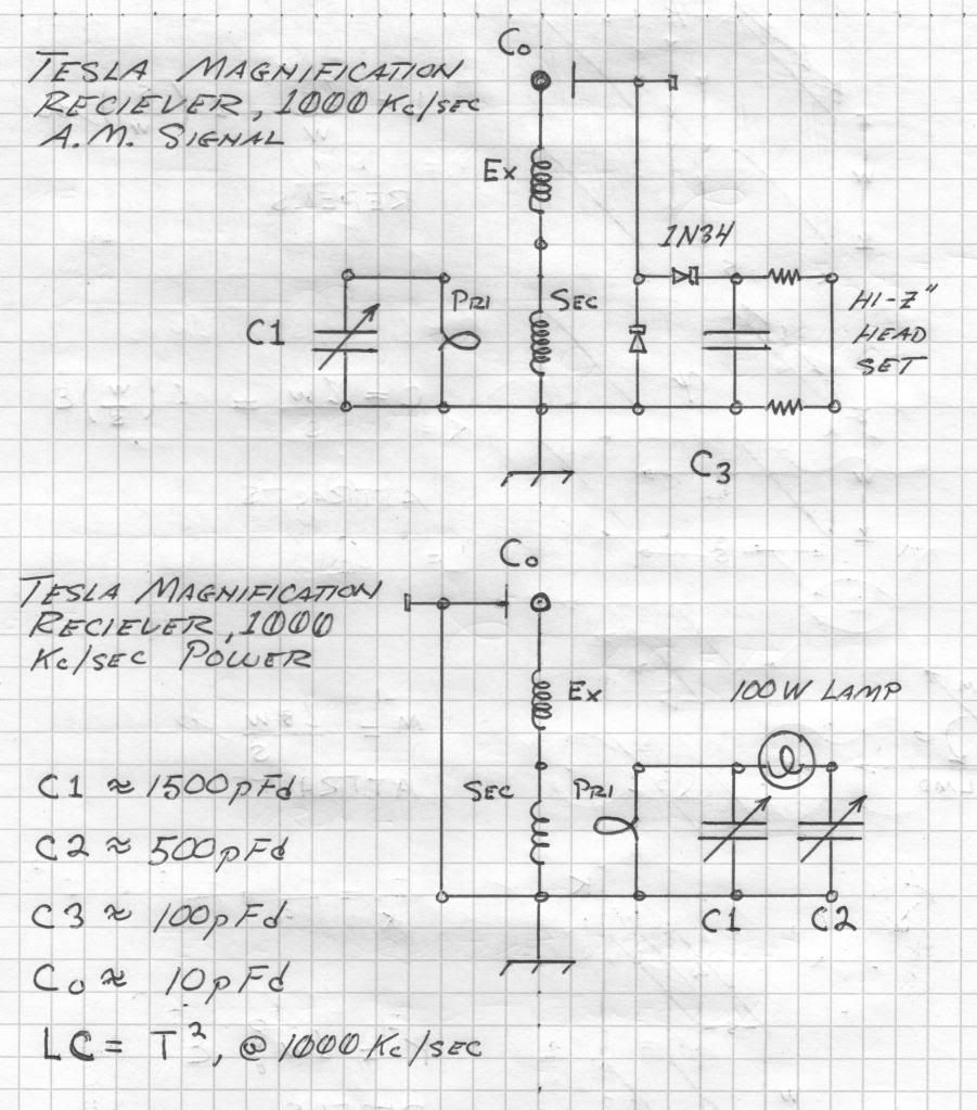
    Jimm, what do you make of this top diagram, in particular the C0 plate, diodes and headphone section?

    Is this a test?
    Fine. It's an interesting adaptation of a "crystal radio
    The amplitude generated at the TC top capacity is loosely coupled into the detector circuit via the pickup plate (which will also affect the TC tuning depending on how close it is).
    You may get some tuning affects with the primary viable cap, but it's performance is dependent upon the coupling setup.

    Leave a comment:


  • Geometric_Algebra
    replied
    Pri/Sec System Testing


    Notes:

    1. Secondary Design Summary:

    D=20in=0.508m
    N=30 turns
    L=pi*D*N= 47.877m
    lambda/4: 47.878m
    lambda: 4*(47.878)= 191.5m
    f=c/lambda=2.998E8/191.5= 1566kcps
    (2/pi)*f= 998 kcps

    2. Split ring is a 0.080" solid copper wire loop of 20" diameter mounted in fixture 0.375" above secondary.
    3. Primary loop(s) excited with 6sn7 triode driver circuit (based on Eric's design).
    4. Current measured via field intensity meter: Simpson 270, 50uA range, 1n34 diode, 2.425" diameter pcb disc terminal. Frequency measured with oscilloscope.
    5. Primary capacitor: 5nf experimental made of pcb plates.
    6. Ground is 10 ft (?) welding cable + 5 copper rods.
    Last edited by Geometric_Algebra; 07-15-2013, 05:48 AM. Reason: typo

    Leave a comment:


  • Aaron
    replied
    Eric Dollard

    This is an interview of Eric Dollard by me on July 6th, 2013 a few days after the Bedini-Lindemann 2013 Conference.

    Eric Dollard Interview July 6, 2013 - YouTube

    I wanted to post the HD video interview but it was 4gb and it wouldn't process so that is the audio with pictures of relevance.

    Yesterday, I interviewed Eric Dollard again and this is being prepared for release. You might want to be sitting or actually even lying down when you hear this one - a little Zofran might be helpful. I'm serious.

    Anyway, anyone interested in what Eric's personal take is on all of the recent happenings needs to hear this other interview that took place early yesterday morning.

    Leave a comment:


  • dR-Green
    replied
    Jimm, what do you make of this top diagram, in particular the C0 plate, diodes and headphone section?

    Leave a comment:


  • dR-Green
    replied
    Originally posted by brusers View Post
    I also noticed the sensitivity around the cable was not much. I almost had to touch it to effect the signal.
    What cable do you mean?

    Originally posted by brusers View Post
    What I think i need to do is just start over. And like you mentioned try for a local AM station. It will be easier to experiment with, rather than waiting for someone to CQ.
    I see. Yes you will have trouble with that for sure. In the meantime you could try tuning it down to the MW band, it should work even though it was designed for a higher frequency. I think to make use of the ham bands you will need 2 coils or work with someone else so there's some known or continuous signal to work with.

    Leave a comment:


  • dR-Green
    replied
    Originally posted by Farmhand View Post
    Yes, I found that a 12 volt Tesla coil emissions could be picked up on a car
    radio from kilometers away. And my small Tesla coil can pick up the radio
    ground connected or not. Tesla talks of signals and power transmission when
    he speaks of power he means many Watts, the beach video showed a signal
    and even I could do that.

    Tesla also said that the planet needed to be thrown into resonance to see
    the low loss power transmissions. It cannot be done on the small scale.
    Hey Farmhand. No range tested here but similarly the radio out in the garage was picking up the interference up in the 89 Mc FM range when I was testing what turned out to be an unstable RF amplifier. But equally I could connect an AV plug and speaker to the earth of all the mains sockets and light switches out there with no antenna at all, just the earth connection. It's quite possible in that case that the radio was picking up the signal from the earth cables.

    I think the fact whether "it cannot be done" remains to be seen. In my opinion it is possible in theory due to the principle of harmonics and resonance. Although keeping in mind discussions we've had in the past. This gives me an idea for an analogue (and digital) experiment I'd like to try with a drum.

    What was the setup when you were receiving radio without ground connection? How was it all connected etc.

    Leave a comment:


  • jimm
    replied
    Originally posted by brusers View Post
    Hello there,

    Yes I tested the bandwidth, and it was rather wide, I dont recall the figures. Which is why I am assuming I tuned/built something wrong. Like I mentioned before, there was not two peaks. The two peaks being the transverse and longitudinal as eric mentions in a few of his videos. So yeah, I agree, I think that is what I have going on here. I just need to keep rebuilding until I find what I need.

    About the beach video. I'm going to assume it's not Hertzian, and it is what Eric says it is. I'm not sure of the distance over the rocks, but he was picking up a pretty strong signal. I've personally built smaller coil arrangments that allowed me to send one wire power through my water pipes, from my basement to the second floor of my house, to a receiver coil arrangment, running a DC motor and a couple incandecent bulbs. They seemed just as bright/powerful as when I hooked them straight to the sending unit. (can't do that with Hertzian). So I know what Eric is talking about is real. I just never at that point thought about using it for radio reception/transmission. Also my arrangments at that point limited me to about that distance. They somewhat resembled the modern day tesla coils, and could not be designed good enough to get much further, so I kind of burned out on experimenting with them. Which is why I'm back at this now. There seems to be quite a bit of information out now on how to go about experimenting, thanks to Eric jumping in and having his work posted.

    Br,

    Marcel
    Don't know how you have a broadband TC, perhaps you can tell us how you did that?


    What frequency and power were you using input and what percentage were you able to recover when you transmitted power? Real Tesla mode is VLF and high voltage. if you don't have transmitter anywhere doing the above, then the receiver is Hertzian.
    Note that Eric DID NOT light any bulbs on the beach at 3000 feet, I think it was, but was able to in the garage. All he had was a radio signal, ...which required a radio to receive.

    The system is supposed to be able to recover 98% for at least hundreds of miles. I haven't seen it yet. In fact, I haven't seen for 300 feet!
    If I am wrong, please direct me to a documented case.

    Now, if I am annoying you by inadvertently going against "church doctrine", I apologize and will shut up. We don't need any more "holy wars".
    If you want to believe that the entire 160 meter signal came though the ground, you are entitled to do so despite your own evidence to the contrary.

    Leave a comment:


  • brusers
    replied
    Originally posted by jimm View Post
    Hello Marcell,

    Have you tested the BW? What is the center frequency?
    Hello there,

    Yes I tested the bandwidth, and it was rather wide, I dont recall the figures. Which is why I am assuming I tuned/built something wrong. Like I mentioned before, there was not two peaks. The two peaks being the transverse and longitudinal as eric mentions in a few of his videos. So yeah, I agree, I think that is what I have going on here. I just need to keep rebuilding until I find what I need.

    About the beach video. I'm going to assume it's not Hertzian, and it is what Eric says it is. I'm not sure of the distance over the rocks, but he was picking up a pretty strong signal. I've personally built smaller coil arrangments that allowed me to send one wire power through my water pipes, from my basement to the second floor of my house, to a receiver coil arrangment, running a DC motor and a couple incandecent bulbs. They seemed just as bright/powerful as when I hooked them straight to the sending unit. (can't do that with Hertzian). So I know what Eric is talking about is real. I just never at that point thought about using it for radio reception/transmission. Also my arrangments at that point limited me to about that distance. They somewhat resembled the modern day tesla coils, and could not be designed good enough to get much further, so I kind of burned out on experimenting with them. Which is why I'm back at this now. There seems to be quite a bit of information out now on how to go about experimenting, thanks to Eric jumping in and having his work posted.

    Br,

    Marcel

    Leave a comment:


  • jimm
    replied
    Radio Tesla

    Originally posted by brusers View Post
    @dR-Green, and others that have been actively building coils.

    I put together a primary/secondary setup for the 160 meter band. Last night when I finished it and got it ~tuned.. I hooked it up to my receiver (old Kenwood R-300) and was hearing a lot of stations and CW action. This was exciting, as before I put up a regular dipole in my apartment, for the 20 meter band, and got absolutely nothing. I even went to the top up a nearby hill with the dipole (same receiver) and got a few strong Russian broadcasts, but not much. I'm on the first floor of the apartments, they are completely made of concrete and metal. So I'm assuming the ground reception was working, as I doubt many standard radio waves could make it in here.

    This morning I got up and tried to see what I could hear with the tesla setup, and got nothing. I know this is normal with standard radio Hertzian waves, but I was assuming with the ground transmission/reception the night/day thing would not matter. I'm curious, has anybody with a semi-successful build noticed any difference in reception during the night and day?

    Thanks,

    Marcel
    Hello Marcell,

    You did a quasi-science experiment without knowing it.
    You proved that in your configuration the device works for EM reception, thus the F layer is still making a difference.

    This the exact point that I have been trying to make about the "Dollard Beach Demo". It was hertzian mode.
    You will get some em though you steel/concrete structre, attenuated, but it will work, just like a cell phone does. The effectiveness of a Faraday cage has to due with the closeness of the screen mesh called aperture.

    Chicken wire will work for HF and below, but not for microwaves, for instance.
    Take a look at the glass on your microwave. notice how small the mesh holes are.

    Also tesla coils are usually hi-Q, so unless the band is real active, the chances of hearing something in a narrow range of frequencies within the TC bandwidth also diminishes. The TC is working sort of like the "preselector" on a ham rig, but it's not that easily tuned in it's standard TC config.
    Once you tune away form the TC's specific BW, you will be down many db.

    Have you tested the BW? What is the center frequency?
    Last edited by jimm; 07-14-2013, 07:02 PM.

    Leave a comment:


  • brusers
    replied
    Originally posted by dR-Green View Post
    Hi Marcel. This might seem like a stupid question, but before anything else are you sure that nothing has moved and no cables have come loose etc? Did you try retuning it and still get nothing?
    Hey,

    Yes I had left it the same when I went to bed, just to make sure I didn't mess anything up. I was excited to get back up and listen to it. I think it's possible I just had it tuned up wrong. For example I never saw two peaks.. as Eric mentioned before. I also noticed the sensitivity around the cable was not much. I almost had to touch it to effect the signal.

    Before I had it made as so, 41cm diameter, 20 turns rg-174 secondary, 2 turn primary of some 8mm coax, and a capacitor made equal surface area of copper stripping glued on two sides of a thin sheet of plexiglass type material. I rewound everything to be more like your original build, 0.8 mm enameled wire for both primary and secondary, keeping the 20/2 turn ratio. Now I get nothing, and it's 21:45 here in Finland. Should be hearing something. I get up at 0430 tomorrow, so I will check it again then.

    What I think i need to do is just start over. And like you mentioned try for a local AM station. It will be easier to experiment with, rather than waiting for someone to CQ. I will use solid copper I think as well, on the next primary, and think up a new cap.

    btw, (and to anyone reading this) on this comparison of Tesla transformer reception VS crysal radio.. I imagine it's easy for someone to argue that the phase difference is created by compnents.. e.g. coil phase shifting, etc. I don't see where this could happen in either setup, does anyone (more technically inclined possibly) see any possibility of this?

    Thanks for the reply. As I get my setup to a point where I feel it's on the right track, I will start posting pics and data. And thank you for keeping your journey on the forum. I went all the way back, printing out your posts and replies as you built.. 150 something pages.. try to make it a quicker journey next time..

    Thanks again,

    Marcel

    Leave a comment:


  • dR-Green
    replied
    Originally posted by brusers View Post
    This morning I got up and tried to see what I could hear with the tesla setup, and got nothing. I know this is normal with standard radio Hertzian waves, but I was assuming with the ground transmission/reception the night/day thing would not matter. I'm curious, has anybody with a semi-successful build noticed any difference in reception during the night and day?
    Hi Marcel. This might seem like a stupid question, but before anything else are you sure that nothing has moved and no cables have come loose etc? Did you try retuning it and still get nothing?

    I haven't made any "scientific" observations on the matter in terms of radio reception, but I have noticed small variations in coil resonant frequencies between night and day, and from one day to the next. But I was always able to receive the same station regardless of all that, I didn't have to retune it every day, but some other stations like China Radio would come and go by the minute. But as I say there was no scientific measurements involved in any of this, I just got an audio output so I have no idea if there were differences that might be causing you problems, I would expect you to be able to get something by retuning it though. I'm not sure that it would be possible to receive absolutely nothing unless something is broken in the setup. Do you know the nearest AM transmitter to you? Try tuning in to that.

    Leave a comment:

Working...
X