Crystal Set Initiative
Geometric Algebra,
Excellent work and you have been very hard at it as we can all see.
Went through your Image Shack pictures and can see the progress you were making during the build.
Is the TEK scope shot of your pulse from the Impulse Generator?
The Copper discs above the assembly also of interest if you could explain please.
What do you think is going to be the result when the Transmitter is powered up fully?
Do you have a receiver built?
Can your system be modulated at all by any of the conventional means, AM, CW etc and assuming this is what the 12AU7 is for?
Did you find working with Vacuum Tubes an exciting experience?
Sorry for all the questions but most interested in your efforts.
Still reworking the Pulse Generator here but have simply got too much on my plate at the moment.
Thanks.
Smokey
Announcement
Collapse
No announcement yet.
Eric Dollard
Collapse
This is a sticky topic.
X
X
-
Wow! This is just great!Originally posted by Spokane1 View PostThis is a fuzzy photo of Eric doing tuning adjustments on a reproduction of the 1989 Borderlands Tesla One-Wire Transmission video demonstration this past week end.
His technical consul was invaluable and by the glow of the appliance lamp you can see that some progress is being made. I would estimate we were at about 60% of full illumination when he finished. More tuning is needed. This will be done using a signal generator and separating each section of the system so that they will be brought into alignment at 2.3 MHz, which is the operational frequency of the Diathermy Machine.
The 1B22 arc tubes seem to be melting and I am searching for replacements.
Eric claims that he could feel some pressure coming off the appliance lamp. I couldn't feel anything - but then again I'm not that sensitive. Hopefully we can reproduce the same kind of energy that was generated in 1989 and begin to charge some capacitors with it at a distance. Once that is accomplished we can dig into this phenomena much more deeply.
IF we can get it to work right we might be able to bring this setup to the Bedini-Lindemann Convention in Hayden, ID at the end of this month.
Spokane 1
Not only just seeing Eric doing the tuning, but also seeing people like you making progress together really shows the dawning of a new age is right at our doorstep.

Leave a comment:
-
-
Vacuum Tube 1B22
Nebraska Sales had large quantities of these at US$9 but now all gone.
Please call me off line as I now refuse to nominate sources for VTs publicly.
Have three here but in use.
Also have a 1B23 and we are now seeing the problem arise with respect to Vacuum Tubes.
Somebody comes out with the use of one of these and TD&H come along and buy them all.
I was one of the first to identify a source for the 1B22 but will in future only disclose to those that ask off line and I know and with a substantial reason attached.
Some of you here may have these 1B22 Tubes and if you don't think you will be using them, please forward gratefully on to Eric - Thankyou!
Diathermy is a good starter and like the setup.
Still like the Ford Buzz Coil with the 1B3, sparkplug and Tesla Coil, just so simple and a poor man's option.
Have one half built and should finish.
1B3 or 1G3 are ex TV and many available.
Thanks for the update.

Smokey
Leave a comment:
-
Eric Dollard providing technical assistance - May 2013
This is a fuzzy photo of Eric doing tuning adjustments on a reproduction of the 1989 Borderlands Tesla One-Wire Transmission video demonstration this past week end.
His technical consul was invaluable and by the glow of the appliance lamp you can see that some progress is being made. I would estimate we were at about 60% of full illumination when he finished. More tuning is needed. This will be done using a signal generator and separating each section of the system so that they will be brought into alignment at 2.3 MHz, which is the operational frequency of the Diathermy Machine.
The 1B22 arc tubes seem to be melting and I am searching for replacements.
Eric claims that he could feel some pressure coming off the appliance lamp. I couldn't feel anything - but then again I'm not that sensitive. Hopefully we can reproduce the same kind of energy that was generated in 1989 and begin to charge some capacitors with it at a distance. Once that is accomplished we can dig into this phenomena much more deeply.
IF we can get it to work right we might be able to bring this setup to the Bedini-Lindemann Convention in Hayden, ID at the end of this month.
Spokane 1Attached Files
Leave a comment:
-
Cosmic Ray Detector
John,
Thankyou for the CRD material and believe I understand what is required and will try and get it charted soon.
Actually did some of this when setting up the equipment to find the best capacitor but will chart this time.
The LMD material - was that developed from Eric's CIG?
Gives us an idea of what is required or what results we should be achieving.
Have eventually received a right size transformer for the 5R4GYB and rebuilding the Pulse Gen now.
Smokey
Leave a comment:
-
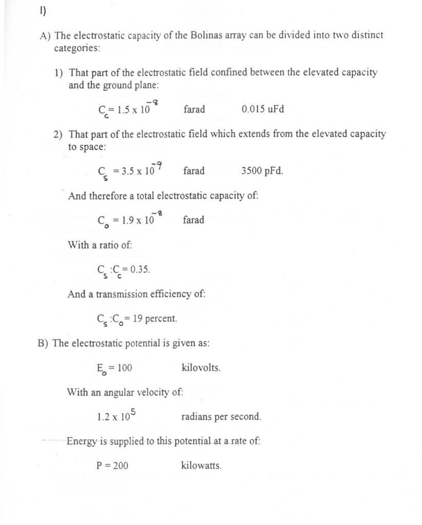
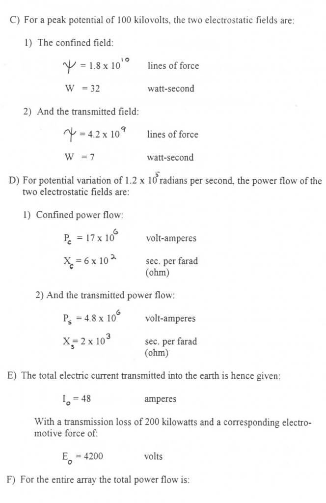
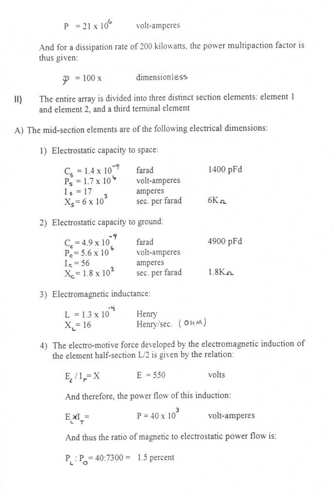
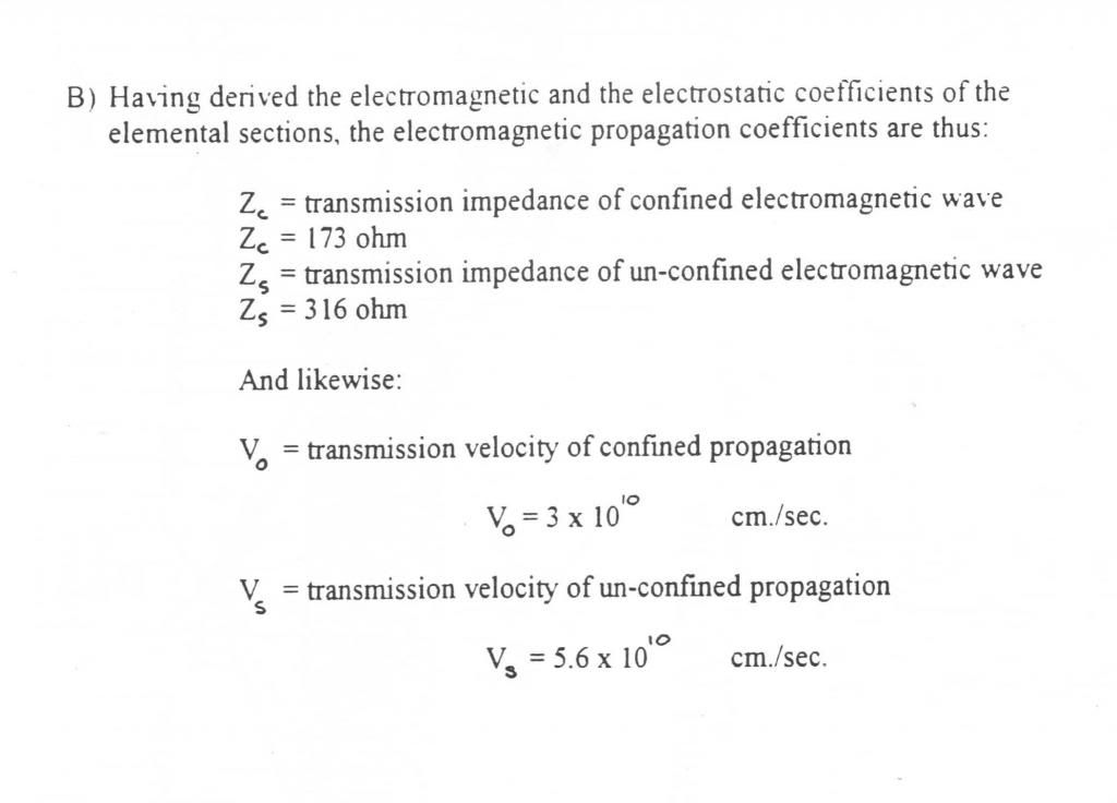
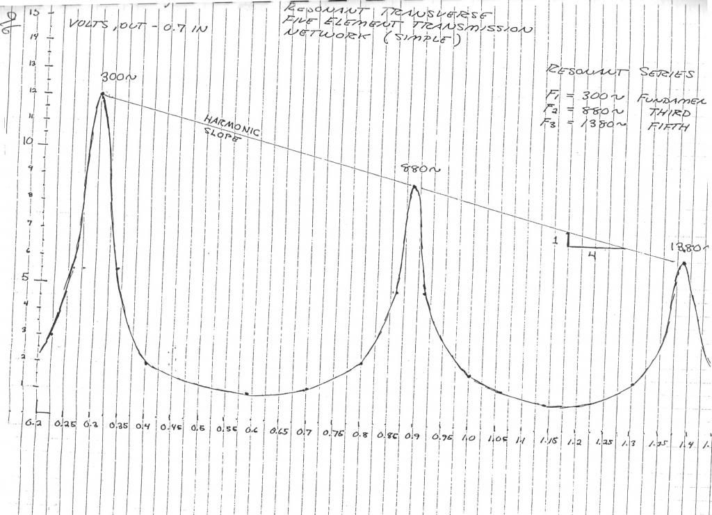
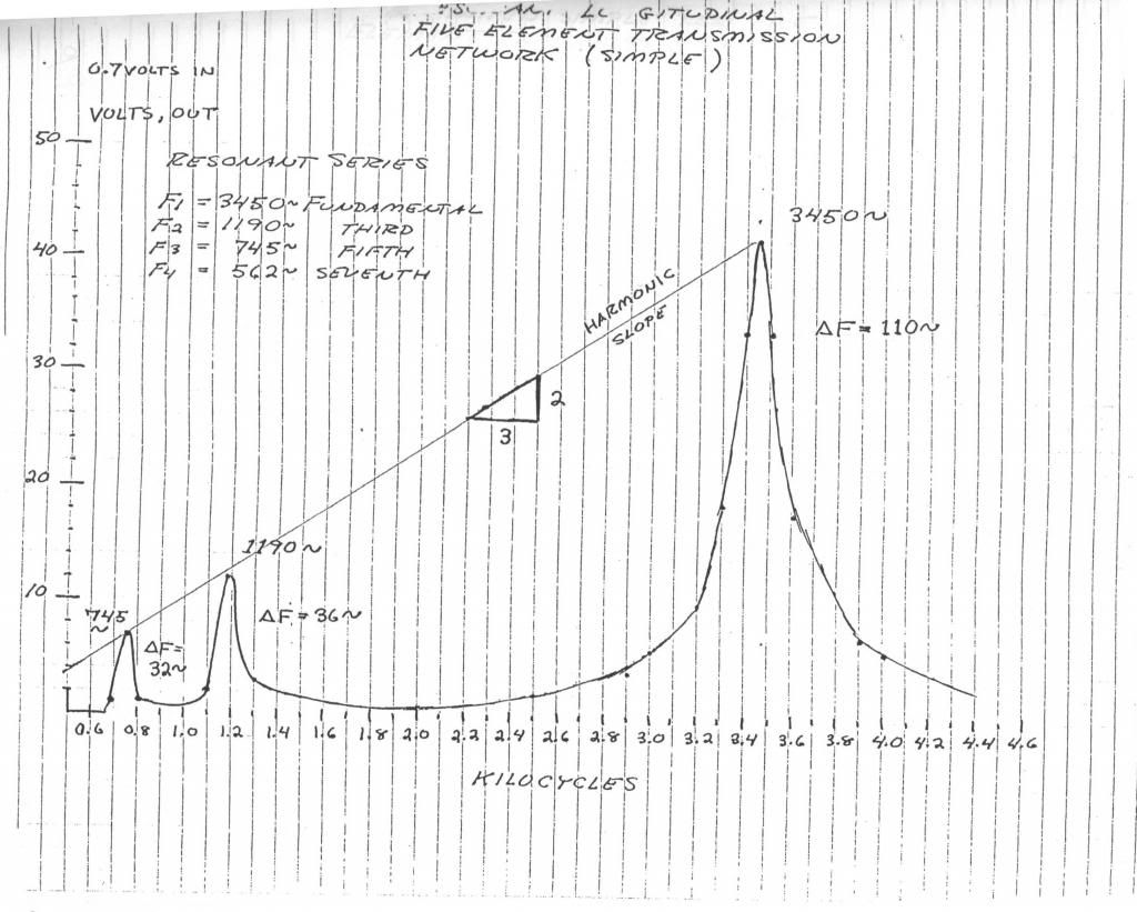
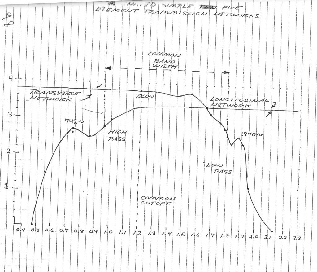
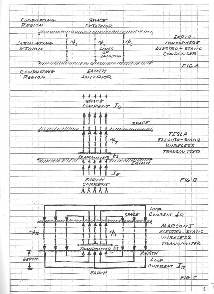
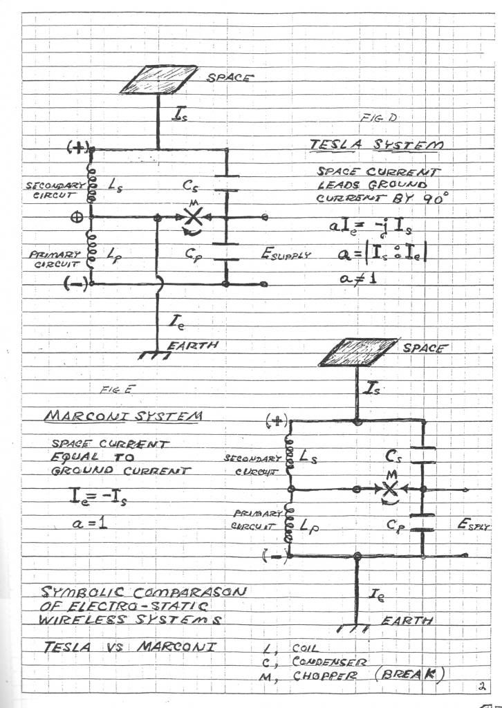
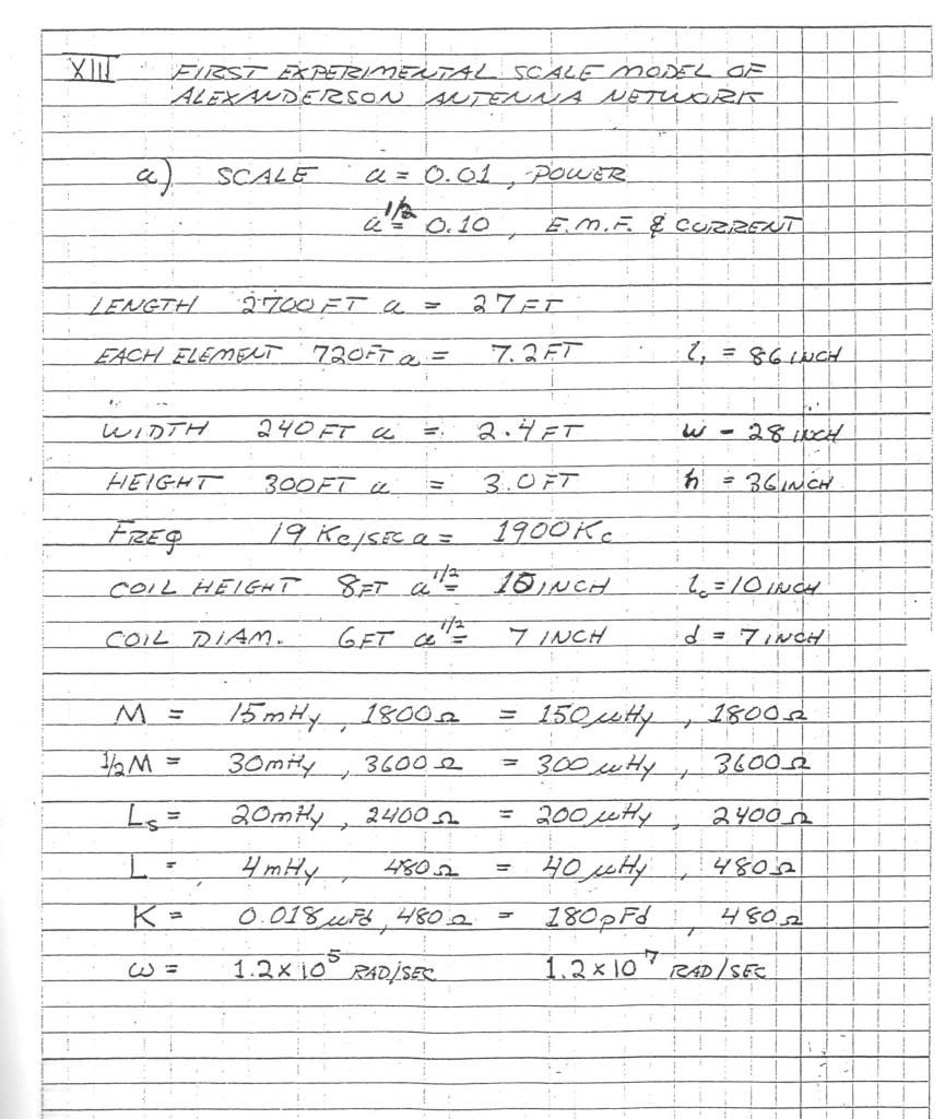
I apologize for the poor picture quality, they are scans of photocopies:
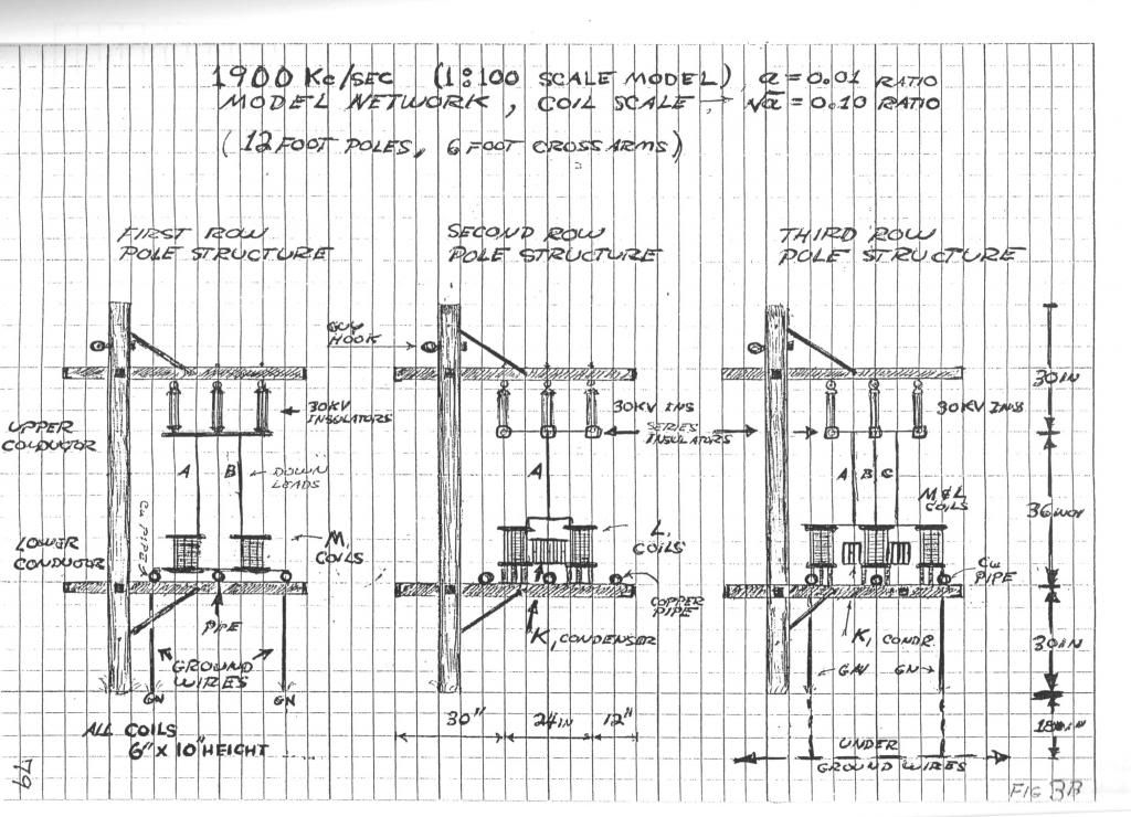
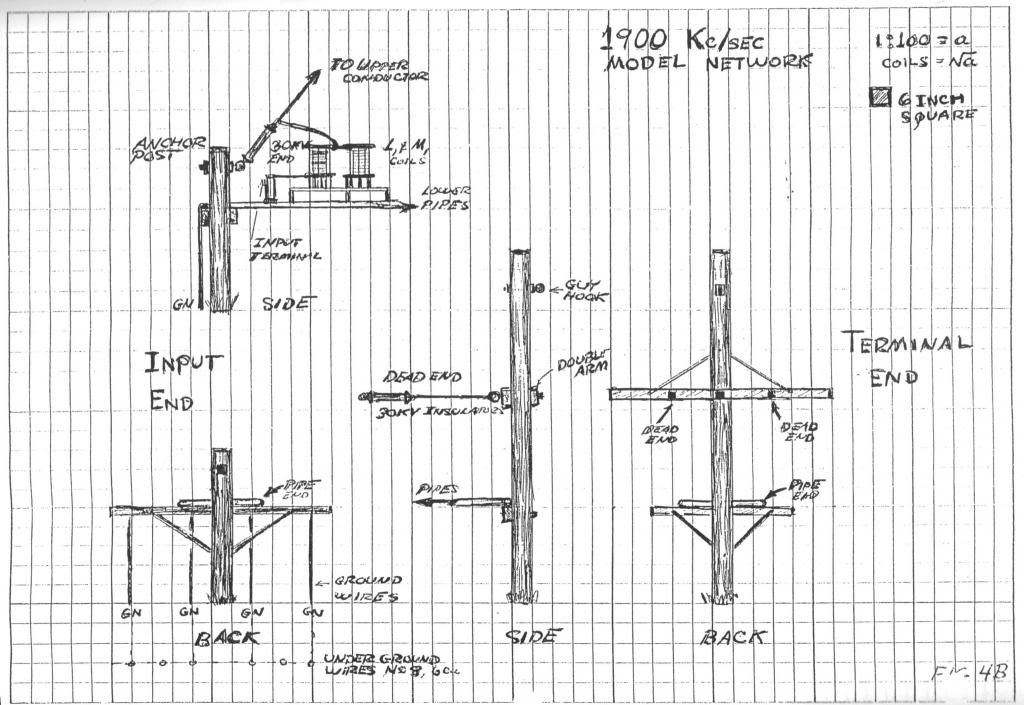
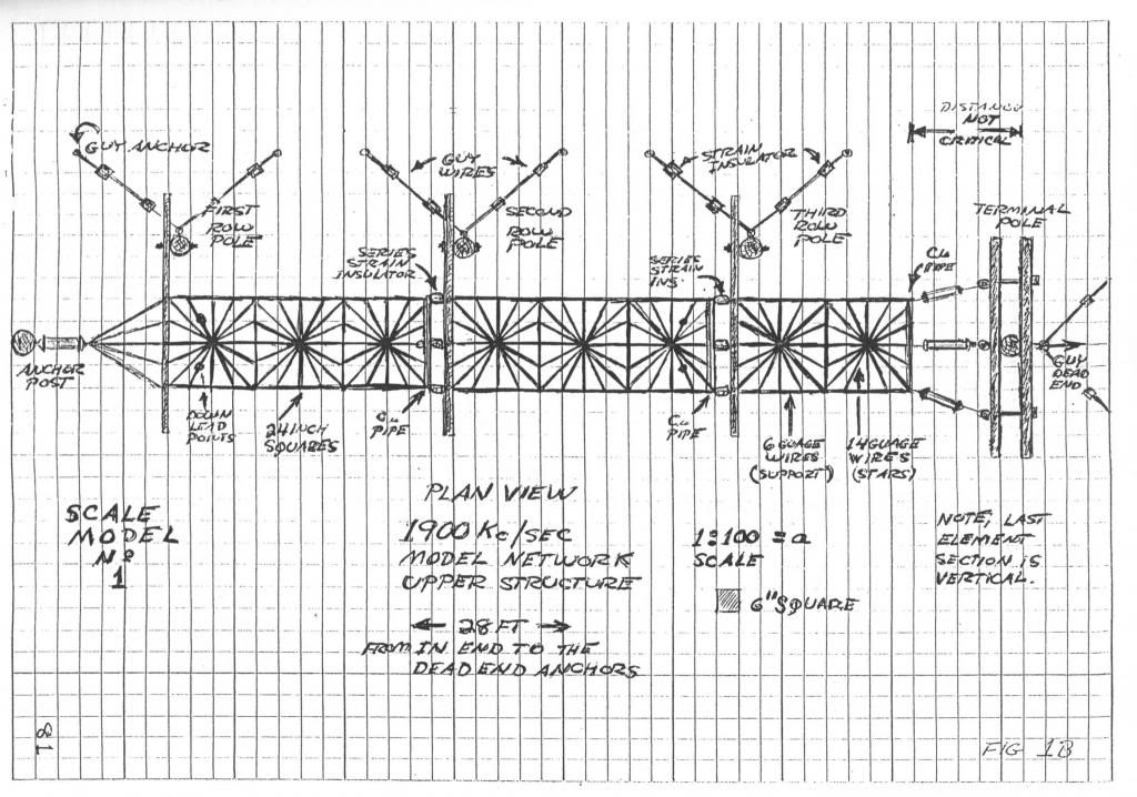
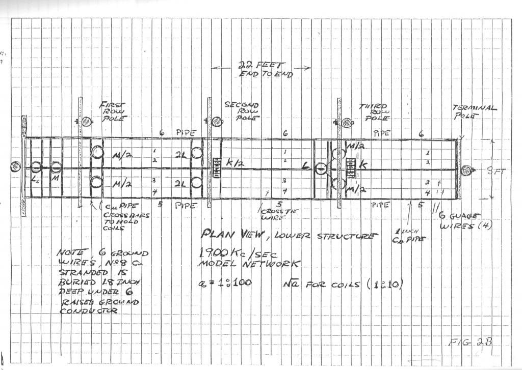
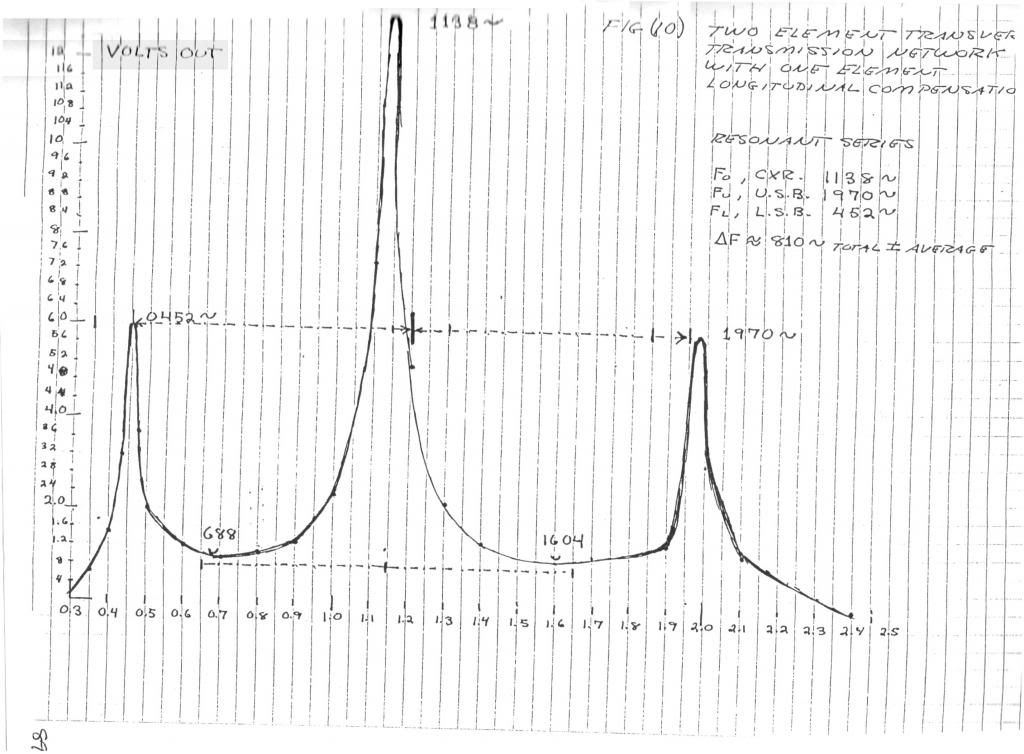
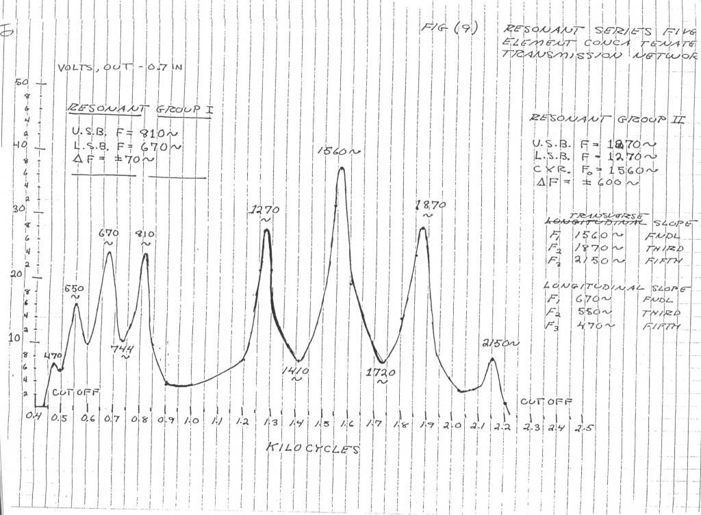
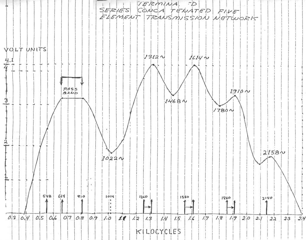
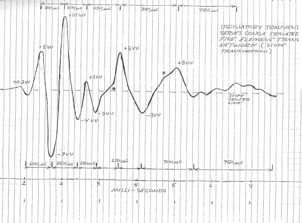
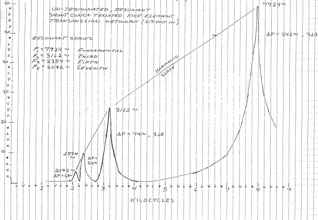
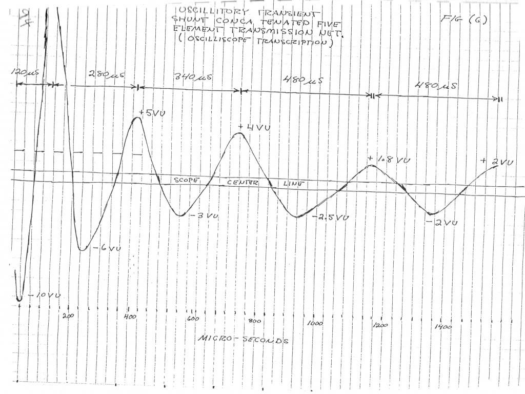
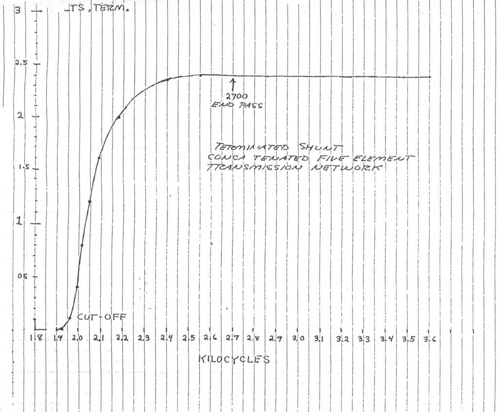
Leave a comment:
-
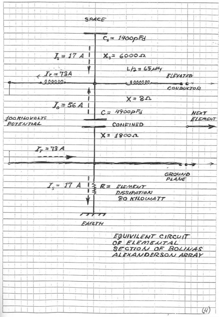
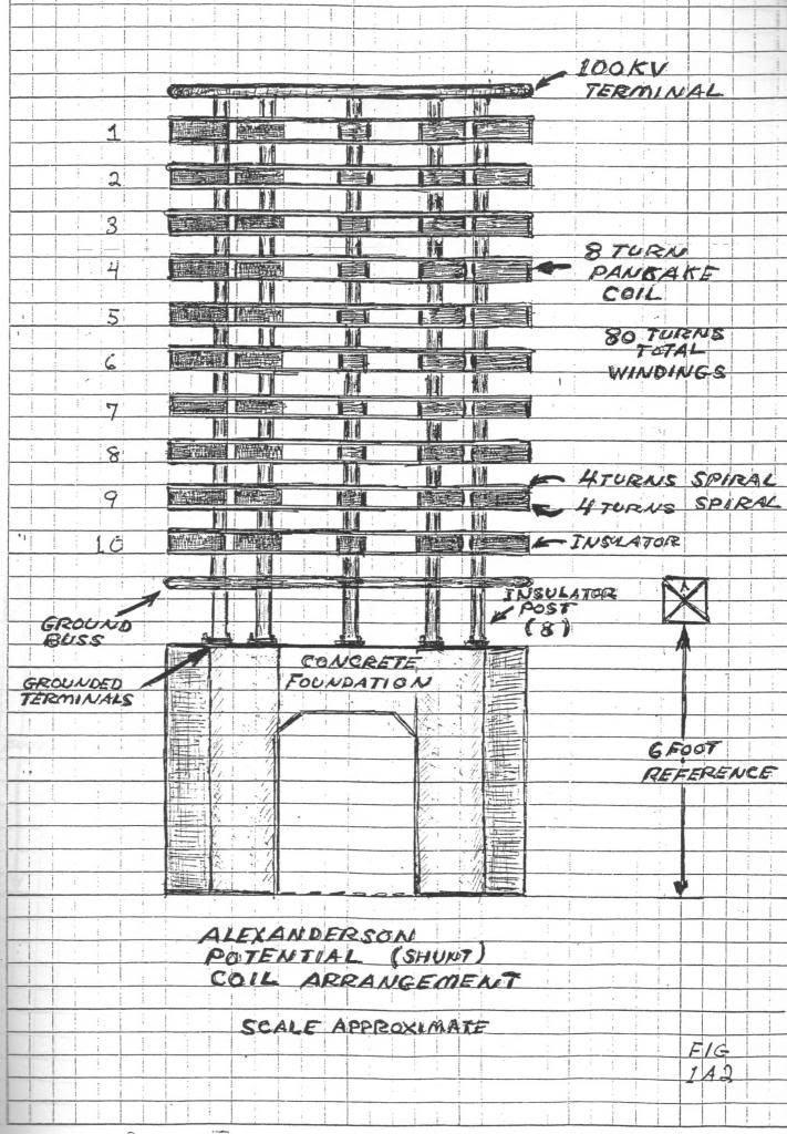
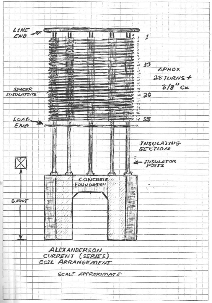
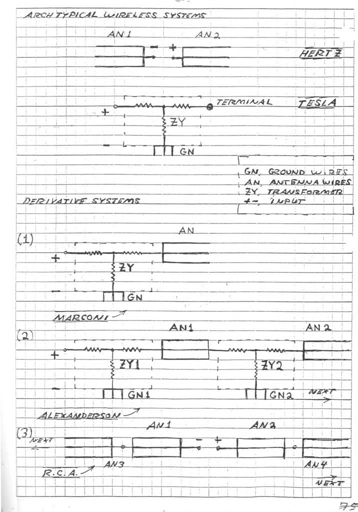
I missed putting in some other pages in the resurfaced material written by Eric, on the LMD vs TEM waves. Here is the rest of the content:
(this comes before the material released previously)
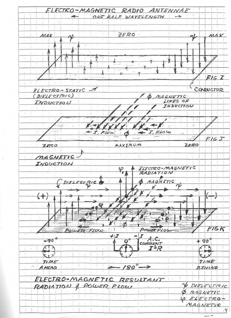
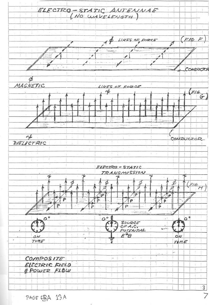
Leave a comment:
-
Update for Cosmic Ray Detector
Here is the latest schematic:
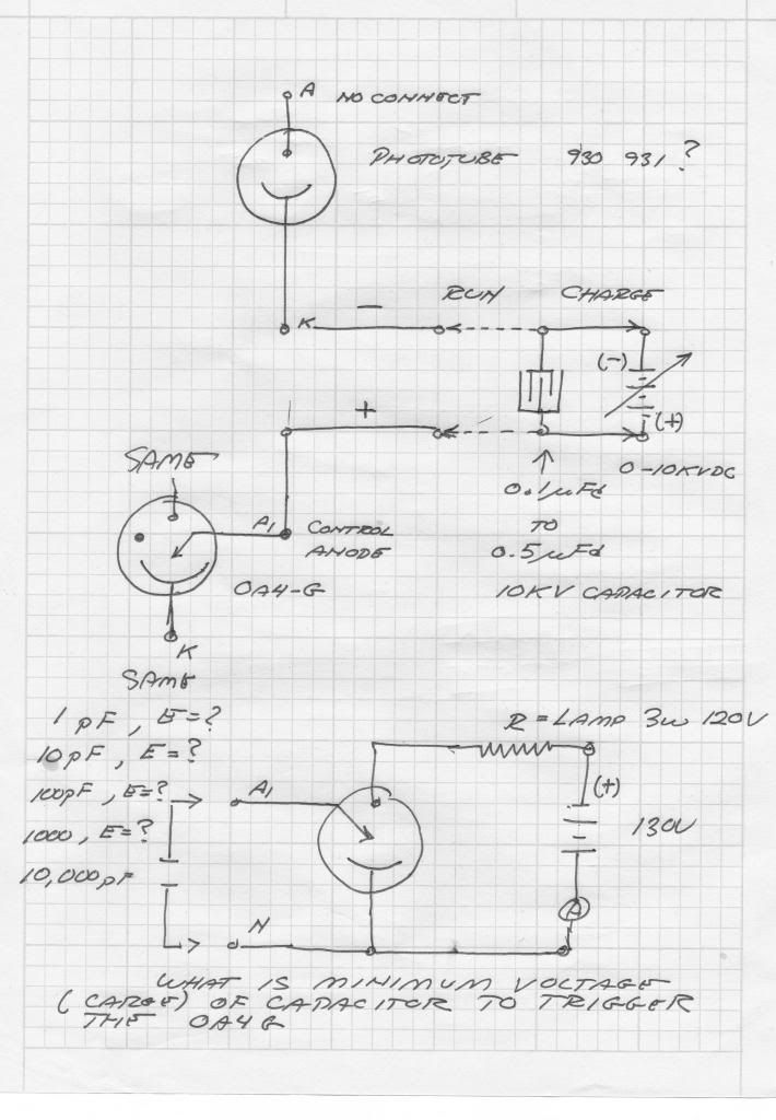
A capacitor has been added to charge the cathode to a negative high potential. This facilitates the tube being able to emit. The capacitor will be in one of two states, either charging (out of the circuit), or running (connected to the cathode):
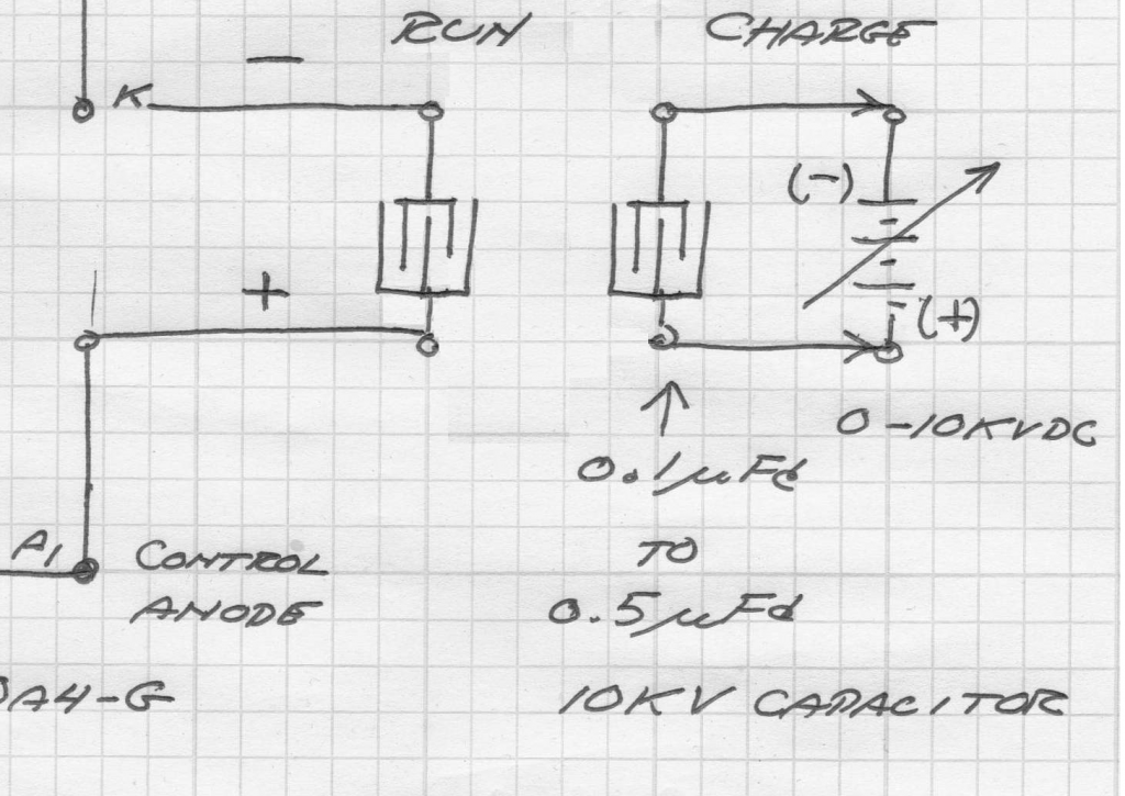
The HV DC charging source must not be in the tube circuit. The smallest possible capacitance that still allows the tube to fire is desirable. A small capacitance won't have enough stored energy at low voltages however, so high voltage DC is required: 0-10 KV.
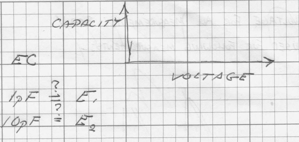
Different capacitor values at different voltages need to be tried, experimentation is required. Curves need to be drawn showing the minimum voltage at a given capacitance is required for the tube to trigger:
Leave a comment:
-
Overall, I get much lower output using this scheme. I moved the probes closer to the transistor to see what it was actually doing, and I guess it's floating ground on the coil; not sure what makes it switch the signal from one side to the other, but I do know I'm not getting a very good current drive through the transistor... I'm trying to figure out how to put an PNP there instead; but don't know how to invert the TL494 output...
I think that if I get a more proper current that the echos will go away.
Leave a comment:
-
Click to edit
LMD Mystery Pulses Test 4 - YouTube
I thought maybe that the oscillation of the emitter possibly biased it to the gate which caused it to conduct, but that turned out not to be the case, and the bias between emitter and gate is 0 during the time of oscillation.
They also appear differently on different scopes (different probes?)
I updated the schematic to include equivalent circuits for the probes that are attached in-circuit (or nearly in circuit). But I don't think they explain the oscillation. I was also moving probes, and wondered what would happen if I rebiased the ground to real ground, and ended up shorting ground to the emitter, thereby bypassing the bridge rectifiers and the coil, but still I get an oscillation in the coil.
... So I went looking for what sort of thing makes waves chirp... I remembered something from one of dollard's videos about the math that is per sec^2... which means the decay happens not just with time, but more and more as time goes. How do I compensate for that? What if I use a conical coil that's good for wide band signals?Last edited by d3x0r; 05-27-2013, 03:02 AM.
Leave a comment:
-
LMD Ground Driven - YouTube
The signal down the line isn't very powerful, but I did notice these strange waves... they really seem to come from nowhere....
LMD Waves 1.jpg
Leave a comment:
-
Originally posted by d3x0r View PostI also was thinking maybe it's how I have it connected to drive....
This is basically how I have it connected now....
This is how I think maybe I should connect it?
The first, in idle state, is in a positive potential, and is filled by current from ground when the transistor opens. Otherwise, a ground potential is the idle condition of the coil, and is drained of ground when the transitor opens; however, the second way makes for a shifting ground, which will mess up the conductivity from gate to emitter?
Had to isolate the ground connection, and the connection to the transistor, otherwise I got bad signal. Even then I got poor signal through the array; I added a connection to positive opposite the ground and it works better. It oscillates at 357Khz now, but not with a lot of power. The pulse generator set at shorted pulse width, or the signal is worse....
wondering if I can improve behavior with the same diodes limiting the positive flow in the normal configuration.... it seems to work well without unlike the ground biased scheme... diodes don't really matter on the positive driven mode...
Wish I understood why it looks like there's a rise just before the pulse generator pulses... for like 10us before, the output has a rising signal at the tail of it's ringdownLast edited by d3x0r; 05-26-2013, 12:15 PM.
Leave a comment:


Leave a comment: