Announcement

Collapse
No announcement yet.

Eric Dollard

Collapse
This is a sticky topic.
X
X
 
  • Filter
  • Time
  • Show
Clear All
new posts

  • Hi Nhopa,
    Some real good experimenting and discovery going on there.. I’ve really enjoyed viewing the pictures and reading about your findings. The desert surroundings and landscape (Coyote country) where you are looks fantastic.

    There hasn’t been much reporting of such grounding experiments on the EPD forum (except from Eric himself), so keep going with it! Albeit hard work with the ground type you’re working with.

    With further thought and results from your analysis, I’ll have some additional questions.

    Around November or so I’ll hopefully be setting up my own star-radial grounding system, but I’ll completely different soil type and a smaller area to work with.

    Great work sir.
    "Doesn't matter how many times you kick the coyote in the head, it's still gonna eat chickens". - EPD

    Comment


    • Cri

      Hi Sputins:

      I am looking for volunteers to help me dig. I live just north of Phoenix, AZ.
      But beside joking I am thinking on some additional testing before putting the wire underground. Since Erik and I were using insulated cable and wire respectively, what would happen if I use bare wire?
      Your questions will be welcome and I may be able test some of your concerns or suggestions.
      Before you do your star radial system, please read the reference I posted about a month ago. The title was "Designing for a Low Resistance Earth Interface - Rev. B-102407". It will save you money on the number of rods required, also it contains some neat calculations. I also have space limitation so my star radial consist of 5 rods, one in the center and 4 more on a 17' radius circle and the rods spaced 60 degrees apart. I have not yet wired the rods together because I still have to buy #6 or #8 copper wire. I am having problem with Eric wiring together all the grounding rods, because in my mind it defeats the purpose of a good ground. On the other hand if Eric wants to create a telluric antenna system, then may be that is the way to go but I do not think you can have it both ways. I may experiment with that set up after I properly wired the grounding rods.
      If Eric is willing to do more testing then he could for instance quantify effective cable/wire length by measuring with instrument the increase of reception strength vs. conductor length and verify best take off point for the telluric signal.

      Comment


      • Yes indeed, excellent work Nhopa!
        http://www.teslascientific.com/

        "Knowledge is cosmic. It does not evolve or unfold in man. Man unfolds to an awareness of it. He gradually discovers it." - Walter Russell

        "Once men died for Truth, but now Truth dies at the hands of men." - Manly P. Hall

        Comment


        • CRI and the distributed capacity

          Hi dR-Green and Sputins:
          Thank you for your comments.
          I need some help sorting out the issue of distributed capacity.
          In Tesla's CSN on page 72 (on the top) it says that the distance between coil turns would have to be reduced to 1/83 of the previous value in order to reduce distributed capacity. This number came about because Tesla reduced the wire size from #10 to #31 in order to have a much smaller distributed capacity.
          I found two US patents, 1342209 and1409352, both of which claims that their invention will reduce coil distributed capacity. One states that the distributed capacity effect is inversely proportional to the spacing between the turns. This seems to be contradicting Tesla's finding.
          Let say we agree with these patent claims, can we benefit by winding our secondary coil in accordance with one of the methods?
          For one of my secondary coil I calculated 19.47 pF (this value will be re verified) for the distributed capacity. According to Tesla one can place capacitors in series with the coil turns to reduce the distributed capacity. In my case how do I determine how many and what value capacitors should I use.
          Eric gives the spacing between coil turn centers as Tau=l/N*2xPi, this equation does not take into consideration the magnitude of distributed capacity as a function of the coil turns spacing. Take care.

          Comment


          • coil self capacitance

            Tesla was totally in the dark as far as the nature of self capacitance of coils. Do not get lost in his confusion. The self capacitance of a coil turns out to be primarily a function of the height to width ratio only. The number of turns or wire diameter has little to do with it.

            Originally posted by Nhopa View Post
            Hi dR-Green and Sputins:
            Thank you for your comments.
            I need some help sorting out the issue of distributed capacity.
            In Tesla's CSN on page 72 (on the top) it says that the distance between coil turns would have to be reduced to 1/83 of the previous value in order to reduce distributed capacity. This number came about because Tesla reduced the wire size from #10 to #31 in order to have a much smaller distributed capacity.
            I found two US patents, 1342209 and1409352, both of which claims that their invention will reduce coil distributed capacity. One states that the distributed capacity effect is inversely proportional to the spacing between the turns. This seems to be contradicting Tesla's finding.
            Let say we agree with these patent claims, can we benefit by winding our secondary coil in accordance with one of the methods?
            For one of my secondary coil I calculated 19.47 pF (this value will be re verified) for the distributed capacity. According to Tesla one can place capacitors in series with the coil turns to reduce the distributed capacity. In my case how do I determine how many and what value capacitors should I use.
            Eric gives the spacing between coil turn centers as Tau=l/N*2xPi, this equation does not take into consideration the magnitude of distributed capacity as a function of the coil turns spacing. Take care.
            SUPPORT ERIC DOLLARD'S WORK AT EPD LABORATORIES, INC.

            Purchase Eric Dollard's Books & Videos: Eric Dollard Books & Videos
            Donate by Paypal: Donate to EPD Laboratories

            Comment


            • Cri

              Hi t-rex:

              It is a honor to get feed back from you, thank you. My take on Tesla that he was overly concerned about the distributed capacity of his coils. Later around the 1920s other people got involved with the subject as shown by the two patent applications.
              Yesterday I found some more info on the subject from 2001. All the equation used in the HAMCALC program. At one time this program was available free from the internet but it seems now disappeared.
              One of the equations calculates out the distributed capacity of coils. The info needed for the calc. are:
              L - coil length (in)
              n - number of turn
              W - wire diameter (in)
              d - coil diameter (in)
              Co - distributed capacity (pF)
              Sw=L/n
              Sd=Sw/W

              Co=(Pixd/3.6)arccoshSd

              I calculated my secondary coils Co and I got 22.29 pF versus my previous measurement and graphing that gave me 19.47 pF.
              So regardless what Tesla was thinking at his time, it would be nice to eliminate this quantity from my experiment so that I would have one less thing to "worry " about.
              I don't mind experimenting with my coil and to try to insert small capacitors in series with the turns. Perhaps four 5 pF capacitors that would give me an equivalent of 1.17 pF for the coil.
              I ordered my copper grounding wire so once I get it I can finish my star diagonal ground system. For the telluric antenna I will have to buy insulated wire that is rated for outdoor underground service. The wire I used in the experiments is insulated but not for outdoor use. Do you have a suggestion as to what is a minimum gage wire I can use?

              Comment


              • Crystal Radio Initiative update

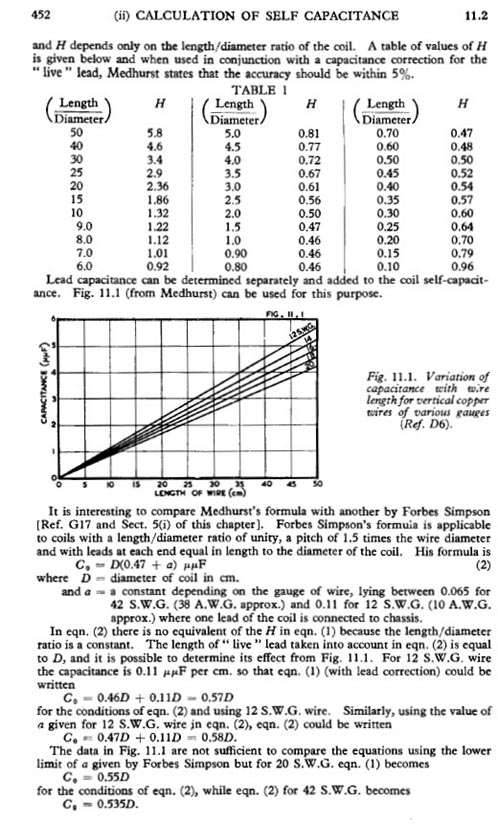
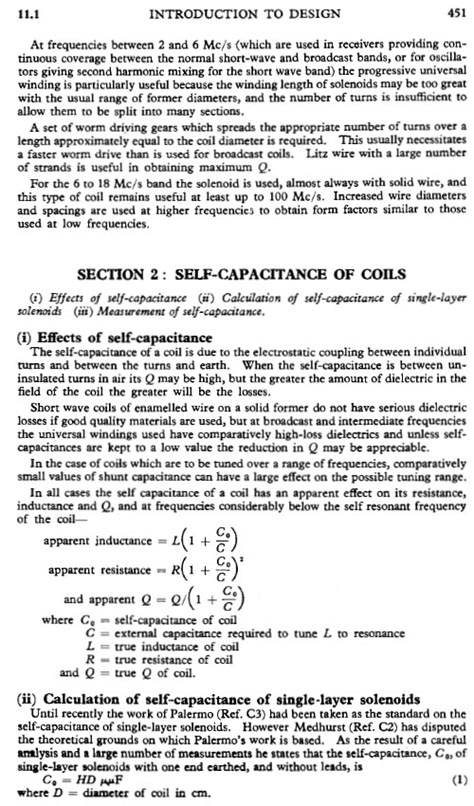
                There was another error found in the Crystal Radio Initiative book. Pages 55-57 or so, there were scanned copies regarding coil self capacitance calculations. The scanned pages showed 451 and 453 but not 452. 452 now shows up in the pdf. Those pages were from the Radiotron Designers Handbook. Just go to the same download link as before.

                Eric says those calculations are very accurate based on his experiments. Do not worry about wire diameter. The conductor should be as large as possible. He already gave formula for wire size.
                Sincerely,
                Aaron Murakami

                Books & Videos https://emediapress.com
                Conference http://energyscienceconference.com
                RPX & MWO http://vril.io

                Comment


                • Calculating Coil Self Capacitance


                  SUPPORT ERIC DOLLARD'S WORK AT EPD LABORATORIES, INC.

                  Purchase Eric Dollard's Books & Videos: Eric Dollard Books & Videos
                  Donate by Paypal: Donate to EPD Laboratories

                  Comment


                  • Cri

                    I have this information but my L/D is .04 so I am out of range, unless I assume H as 1.00?
                    Last edited by Nhopa; 09-22-2015, 02:47 AM. Reason: L/D should read as H

                    Comment


                    • T-rex in the house!

                      Recently in an interview with Aaron, it was Interesting that you say you’ve designed a new type of audio amplifier that’s radically different from regular RCA designs. This new audio amplifier based on Bell Telephone wide band carrier technology and used in the front end of radar receivers. That idea seems pretty interesting and would be very popular. It could generate some additional revenue towards the bigger projects. - Is the idea behind the new tube amp design to amplify certain harmonics that would normally be distorted?

                      There was an overwhelming amount of information jammed into your most recent presentation at the Technology & Science Conference. I’ve watched it over and over. A fantastic presentation!

                      I’ve been researching single ended vacuum tube audio amps, as it would be great to build my own vacuum tube audio amp sometime. As you said everyone likes to use the 300B tube, what other alternative tubes would you suggest for audio work?

                      It would certainly be awesome to hear you go a little deeper into the JJ Thompson topic in the future sometime.

                      I’m looking forward to early November when I will have my workshop and experiments back in action.

                      Sputins.
                      "Doesn't matter how many times you kick the coyote in the head, it's still gonna eat chickens". - EPD

                      Comment


                      • Sputins 2395

                        Because of the requirement of special transformers and the high cost of audio transformers in general it is not feasible to move forward with the audio amplifiers.

                        Moreover, I still have no tools for constructing equipment, nor any real workshop as of yet.

                        It all takes too much money and I have no one to help me. (Polakowski turned out to be an incorrigible turd).

                        Do not get caught up in that 300-B single ended Phantasia.

                        The Push-Pull 6L6-G setup is still the "best for the buck," do not feed your money to the rats.

                        73 DE N6KPH
                        SUPPORT ERIC DOLLARD'S WORK AT EPD LABORATORIES, INC.

                        Purchase Eric Dollard's Books & Videos: Eric Dollard Books & Videos
                        Donate by Paypal: Donate to EPD Laboratories

                        Comment


                        • Originally posted by t-rex View Post
                          Because of the requirement of special transformers and the high cost of audio transformers in general it is not feasible to move forward with the audio amplifiers.

                          Moreover, I still have no tools for constructing equipment, nor any real workshop as of yet.

                          It all takes too much money and I have no one to help me. (Polakowski turned out to be an incorrigible turd).

                          Do not get caught up in that 300-B single ended Phantasia.

                          The Push-Pull 6L6-G setup is still the "best for the buck," do not feed your money to the rats.

                          73 DE N6KPH
                          I am loathed to ask, but what went wrong working with John Polakowski?
                          "Doesn't matter how many times you kick the coyote in the head, it's still gonna eat chickens". - EPD

                          Comment


                          • Sputins 2397

                            Originally posted by Sputins View Post
                            I am loathed to ask, but what went wrong working with John Polakowski?
                            I cannot get into the details on the air about Polakowski's disabilities or transgressions, other than he has received a dishonorable discharge from E.P.D. Laboratories for misuse of funds and failure to carry out commitments.
                            SUPPORT ERIC DOLLARD'S WORK AT EPD LABORATORIES, INC.

                            Purchase Eric Dollard's Books & Videos: Eric Dollard Books & Videos
                            Donate by Paypal: Donate to EPD Laboratories

                            Comment


                            • On the subject of earthing, I've been out taking some pictures of where I'll be setting up. This was the old coal shed, my stuff is the top part and the earthing arrangement will go in the garden in front, about 6-7 metre diameter star/ring, and I'll dig a channel under/through the wall to connect to it. A small structure just to house the coil in the centre might come later.


                              This is the field next door, which as can be seen is mostly like a giant bog and is soaked, the farmer even got his tractor stuck in it a few years ago, so it should be ideal for reception experiments. The whole area is quite marshy. The lab/shed is behind the bushes next to the house with solar panels. The bottom of the field where I'm standing is about 75-ish metres away.


                              The view from the top of the field. I also know the farmers who own practically every field that's in view so assuming that a decent mobile earthing arrangement is possible then experiments can be done over quite a good distance within view.


                              This is an old iron pipe in the ditch between the garden and the top of the field. It was installed 100 years ago to transport water 300 metres or so from a spring to a well on the side of the road for horses. Builders broke the pipe where I'm standing years ago but the idea I have here is obvious. It should extend about 250 metres in one direction and 50 in the other, unless someone else has also been digging and broken it.


                              And about a metre to the left of the iron pipe is what appears to be another spring which as far as I can tell flows independently of any recent rain. All in all the conditions look good!

                              http://www.teslascientific.com/

                              "Knowledge is cosmic. It does not evolve or unfold in man. Man unfolds to an awareness of it. He gradually discovers it." - Walter Russell

                              "Once men died for Truth, but now Truth dies at the hands of men." - Manly P. Hall

                              Comment


                              • In the middle of London?

                                Hi dR-Green:

                                This is a very nice setup. With so much water around you, you should have no problem creating a near zero Ohm ground.
                                I received my #10 gage copper wire today, but my oscilloscope broke down so now I am working on that problem.

                                Comment

                                Working...
                                X