Gold Terminal Capacity
Eric has mentioned that the element gold (Au) has the unique property of having direct contact with the Aether, (Counterspace)? This due to the fact that gold is an inert substance, forms no oxide layer, film or barrier and is also an excellent conductor.
Acquired glom from work are quartz tubes with gold plating on the internal surface. These used gold tubes are no longer fit for purpose due to the gold wearing off, or thinning out from the very ends which ruins them optically.
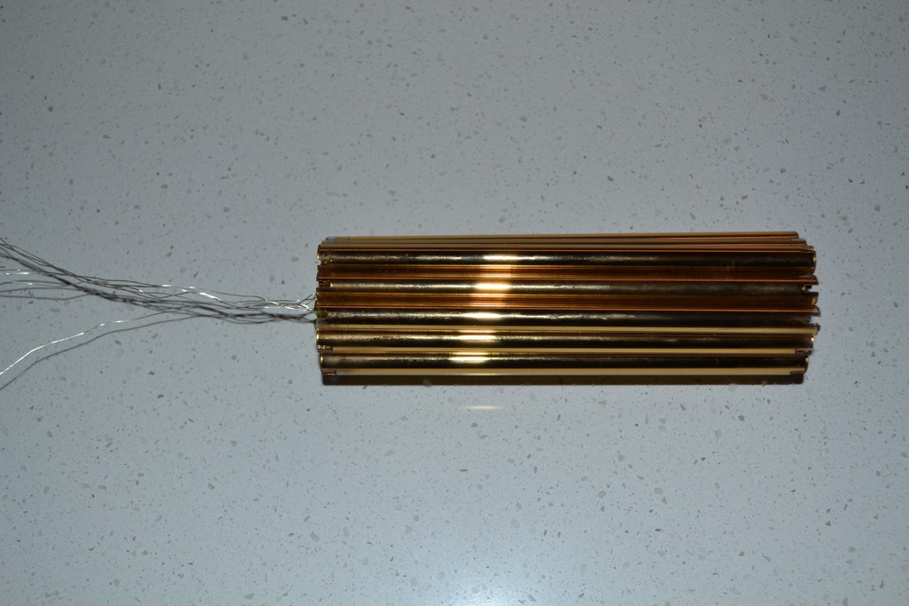
As the tubes are quartz and the gold is on the inside, they can be brought together to form a capacitive structure. One end of each gold tube has a silvered wire connected to the gold via compression to form a good contact.
The combined gold tubes have a total surface area of about 627cm2, or if rolled out flat could form 25cm x 25cm sheet approximately. The isotropic capacity of this configuration is still being determined and measured.
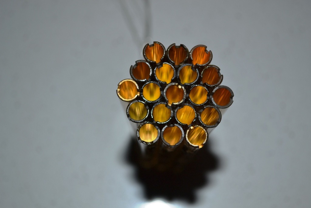
The array of gold tubes consists of 19 tubes, configured in a “flower of life” formation.
This structure is to be used as a terminal capacity for my Tesla Transformer.
Announcement
Collapse
No announcement yet.
Eric Dollard
Collapse
This is a sticky topic.
X
X
-
Live call with Eric Dollard
Starts in 24 minutes - today May 1st.
1. Dial: 1-857-232-0155 at the time you set
2. Enter the Conference Code: 582590
Leave a comment:
-
Originally posted by Alexg800 View PostHi,
I only would like to ask the following:
Your formula lo = 1/4*0.78*c/f
The formula in the calculation lo = 1/2Pi * c/f
There is a difference in the results so as
1/4 * 0.78 = 0.195;
1/2Pi = 0.159
What to use?
Leave a comment:
-
Leave a comment:
-
Originally posted by Alexg800 View PostThanks! Now everything is clear! Very good explanation.
I only would like to ask the following:
Your formula lo = 1/4*0.78*c/f
The formula in the calculation lo = 1/2Pi * c/f
There is a difference in the results so as
1/4 * 0.78 = 0.195;
1/2Pi = 0.159
What to use?
Leave a comment:
-
Originally posted by dr-green View Postthere have been a few updates recently as well as different variations originally.
The latest calculations are in the cri video. There, lo = 1/4*0.78*c/f
the 20% h/d ratio sets the propagation velocity of the coil through the geometry, which will cause the frequency of a 1/4 wavelength wire length to be too low. So in order to compensate for it, the wire length is made shorter to bring the frequency back up to the original value.
If the same length of wire was wound with a different geometry then the propagation velocity would be different, and so the resultant frequency. Because both l and c depend on the geometry.
Leave a comment:
-
dR-Green,
Good to see you back..
What have you been constructing or experimenting with recently? What have you been up to or planning?
Leave a comment:
-
Originally posted by Alexg800 View PostHi dR-Green,
It is splendid that "the L and C both based on the geometry of the coil".
I did not know it and thought how to do it, but here it is already done. Nice!
Concerning the wire length, look on the formula (1)
" Total length of Coiled Wire: Lo = C / W, C -speed of light, W = 2Pi X F."
Where is 1/4 wavelength. May be I do not understand anything?
Look:
Frequency - Wavelength Chart
The latest calculations are in the CRI video. There, Lo = 1/4*0.78*C/F
The 20% H/D ratio sets the propagation velocity of the coil through the geometry, which will cause the frequency of a 1/4 wavelength wire length to be too low. So in order to compensate for it, the wire length is made shorter to bring the frequency back up to the original value.
If the same length of wire was wound with a different geometry then the propagation velocity would be different, and so the resultant frequency. Because both L and C depend on the geometry.
Leave a comment:
-
Since the primary is only a single turn, it seems like an adjustable capacitance on the primary to tune in to the secondary's resonance point is crucial. However, it does not seem crucial for the secondary coil to be resonating at it's natural LC frequency unless you are looking for the highest Q possible. Using just the 1/4 wavelength wire on the secondary, nodes should still occur, regardless of the relationship between the coils inductance and capacitance. Am I off base here?
Leave a comment:
-
Originally posted by dR-Green View PostHi, the wire length is 1/4 wavelength. The L and C are both based on the geometry of the coil, so that is already factored into the calculations. That's why the wire length is in fact about 0.68*1/4 wavelength.
It is splendid that "the L and C both based on the geometry of the coil".
I did not know it and thought how to do it, but here it is already done. Nice!
Concerning the wire length, look on the formula (1)
" Total length of Coiled Wire: Lo = C / W, C -speed of light, W = 2Pi X F."
Where is 1/4 wavelength. May be I do not understand anything?
Look:
Frequency - Wavelength ChartLast edited by Alexg800; 04-18-2016, 01:15 PM.
Leave a comment:
-
Originally posted by Alexg800 View PostHello,
Thanks for your reply. So I am going to build the coil with the ratio H/D = 20% !!!
I only do not understand in the calculation why the wire length must be equal to lambda. In the literature and TESLA patents a quarter of lambda is mentioned. In this case the upper end of the coil will be a high voltage node.
In case of wire length is equal to lambda the upper end is not a high voltage node.
Also in the current calculation nothing mentioned of the LC resonance of the coil. Should LC resonance frequency of the coil corresponds to the working frequency of the coil or not? Can matching LC resonant frequency and working frequency give any advantages?
Leave a comment:
-
Originally posted by dR-Green View PostPictures of who's Tesla coils?
The optimal proportions will be optimal at all sizes because it's based on the geometry and, height to diameter ratio. 0.2 = 1/5 = 20/100
No part of this is meant to make big sparks and waste energy as the rest of the internet would have you believe, so if you want to make things that actually work you can start with the 20% ratio.
But it's not as if nothing will work if you don't do that, you can literally make a pile of old junk work. What's more important is what you learn in the process of building it and getting it to work. After you build this one you will have gained valuable knowledge for the next one.
Thanks for your reply. So I am going to build the coil with the ratio H/D = 20% !!!
I only do not understand in the calculation why the wire length must be equal to lambda. In the literature and TESLA patents a quarter of lambda is mentioned. In this case the upper end of the coil will be a high voltage node.
In case of wire length is equal to lambda the upper end is not a high voltage node.
Also in the current calculation nothing mentioned of the LC resonance of the coil. Should LC resonance frequency of the coil corresponds to the working frequency of the coil or not? Can matching LC resonant frequency and working frequency give any advantages?
Leave a comment:
-
Originally posted by Alexg800 View PostHello Sputins,
Thanks for your fast response.
I see on the pictures that Tesla coils are usually built in according to H>>D, where H - height, D - diameter. What could you advice?
I am going to build a coil where the wire length is 3.75m, it means that
1/4 lambda is 3.75m (lambda = 15m, Freq = 20MHz) What diameter and the height of the coil should be chosen in a proper way? What could you advice?
Alex
The optimal proportions will be optimal at all sizes because it's based on the geometry and, height to diameter ratio. 0.2 = 1/5 = 20/100
No part of this is meant to make big sparks and waste energy as the rest of the internet would have you believe, so if you want to make things that actually work you can start with the 20% ratio.
But it's not as if nothing will work if you don't do that, you can literally make a pile of old junk work. What's more important is what you learn in the process of building it and getting it to work. After you build this one you will have gained valuable knowledge for the next one.
Leave a comment:
-
Originally posted by Sputins View PostThe reason for 20% H/W ratio, given by Eric is based upon Tesla’s fifty foot secondary coil in Colorado. So that is where it derives from: Tesla.
Diameter = 15 Metres
Height = 1.0668 Metres
Number Of Turns = 16 (Final Turn Excluded)
Leave a comment:
Leave a comment: