Announcement

Collapse
No announcement yet.

Eric Dollard

Collapse
This is a sticky topic.
X
X
 
  • Filter
  • Time
  • Show
Clear All
new posts

  • Originally posted by Farmhand View Post
    Oh ok I get it. It's not easy to show a whole setup like that and do everything
    alone, good job. I notice with my setups there is an out of phase resonance
    at a higher frequency than the tandem 1/4 wave frequency, for me the
    tandem frequency is at about 780 kc and the next resonant (out of phase)
    condition is at about 1450 kc depending on the tuning it varies of course.
    Anyway I notice that if things are tuned a certain way the higher frequency
    resonance can be comparable to the lower frequency in maximum voltage but
    the primary and secondary are 180 degrees out of phase. I suppose I ought
    to check the coil as you did to see whats going on. It is interesting. Did you
    try varying the primary capacitance a very small amount or otherwise change
    the primary resonant frequency a small amount and tune both ways ? I found
    that the length of wire other than the primary itself in the primary circuit is
    crucial to tuning as is the ground lead length. I found when I tuned the
    primary resonant frequency to a little bit more or less than what is optimal for
    the tandem tune when I tune to the higher resonance the effect can be
    better. What I see is totally repeatable because it happens with all the three
    coil setups I have to a differing degree. And the primary and secondary become
    180 degrees out of phase exactly.

    I'll do a spreadsheet soon.

    Cheers
    Good work, thanks for the info. I connected a primary condenser last week but then all hell broke loose so I didn't use it for the video. One step at a time I think, it didn't behave as expected at all and until the tuning of the coils is figured out I can see that only making things even more confusing. I've been looking over some of the data from the different extra coils and apparently the "non-existent secondary effect" and peak concatenated potential appears when both coils are tuned to approximately the same frequency, where the secondary and extra coil tuning cross over in the graphs or thereabouts, close enough to call for further inspection, regardless of the length of wire in the different extra coils. I've also managed to increase the extra coil potential and decrease the secondary potential as far as the field intensity is concerned, so I'd say this is controllable through very fine tuning. There are still even more weird things that need to be investigated though. Apparently two separate earthed components (plates/rings) making up the secondary tuning condenser is better than one. Adding more capacitance through a separate earthed plate takes the potential higher than adding capacitance through the earthed ring. By that I don't mean dividing the capacitance equally between the components, I mean adding capacitance in addition to the maximum potential already obtained through the rings.

    And on a side note, shorting the earthed ring into a continuous loop greatly reduces the effective capacitance.
    Last edited by dR-Green; 11-19-2012, 09:53 AM.
    http://www.teslascientific.com/

    "Knowledge is cosmic. It does not evolve or unfold in man. Man unfolds to an awareness of it. He gradually discovers it." - Walter Russell

    "Once men died for Truth, but now Truth dies at the hands of men." - Manly P. Hall

    Comment


    • Jerry Bayles

      Jerry E Bayles at electrogravity.com has come up with some most interesting theories which he appears to prove with Maths with reference to the A vector and also with regard to the Pyramids of Giza.
      An accident when dismantling a 3 piece thin tube antenna which gave a high pitched hiss (high voltage - snake - Caduceus) when it came near the metal roof suggests an Aetheric phenomena which may be linked to Hydrogen.
      Eric might also be interested in this data (John, Dave):

      http://www.electrogravity.com/MASSCO...ntrol_Add1.pdf

      http://www.electrogravity.com/Energy...yPipe_Add1.pdf

      I am into Tubes so will put this one on the project list as it does not appear to be that difficult to replicate but may give us a deeper understanding of the CSI and related phenomena.

      Not even going to pretend I understand his Maths but like this reference to
      'e' which is the natural number of 2.7182818285 (first pdf page12).
      This was labelled as Jerry's 'Eureka Moment'.

      Was going to paste the extract into here but it won't happen.

      On the same page Jerry goes on to talk about 'negative energy' with respect to UFOs.
      This is similar to what I am currently doing with the Joe Cell by block charging into the negative and looks like Hydrogen is the associated gas we are dealing with here.
      Have already proven that this increases the holding charge in the Cell from 2 to 2.5 volts.
      The deeper into the negative the higher the holding charge is what we are attempting to prove here.

      Have also just finished the 600volt +/- minus power supply and this will be used in a like manner in other areas - going negative as against positive.
      What this means is that your positive becomes ground and the negative becomes a minus value like -20 volts with what I am using with the Joe Cell.
      Or you can go deeper into the negative with positive at -20 and the negative at -40 volts - a block negative polarity shift.

      CSI:
      Have been using a small single gang Condenser between secondary and extra and am able to tune for a signal peak in the headphones and this in a testing option to the Copper rings.
      Signal also appears to be louder than with the direct connection.
      Have some large bodied (5.5mm) CV2290 (GEX66) Germanium Diodes coming and will compare with the 1N34A, 1N67A and 1N270 I am currently using in pickup heads.
      Have a letter going off to Eric and hoping he has the time to respond.

      Smokey

      Comment


      • More Info On Mojave Research Installation Graphs

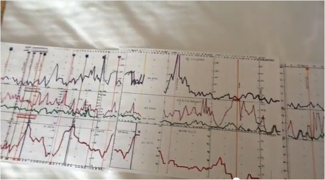
        The following is a written description of the Mojave Research Installation graphs sent to me by Eric. It is a more detailed description of the graphs described in this video: Eric Dollard Describes Earthquake Detection Charts - YouTube


        Picture of graphs

        Description of graphical presentation, Mojave Research Installation, Landers, CA. (Destroyed May 22, 2010 by Olen Bales)

        Four parameters are given in this graphical presentation, all centered in time about the major “Haiti Earthquake.” Each was derived from daily readings at 1600 hrs U.T.C. Which were entered into the N6KPH station log. Said log and graphical records were lost when the installation was ransacked by Olen Bales.

        The first parameter (top) is the daily integrated impulse counter. The integration period was 24 hours and the value on the graph is the square root of the daily impulse count. The impulses are derived from a high pass network connecting to the system geo-phone (seismic pickup) that also drives the seismo-scope and seismic recorder. Seismic waves of less than 500 millisecond duration are passed to the counter, this giving a count of local (50 kilometer) seismic vibrations. Hence this particular graphic presentation is a logarithmic measure of local daily seismic activity.

        The second and third graphical presentation are super-imposed and represent electrical activity. See “System for the Transmission and Reception of Telluric Electric Waves”, by E.P. Dollard. This electric activity was derived from an Earth Signal Antennae Structure. A 1600 foot Beverage (R.C.A.) antenna derived the electrical activity from the displacements in the Earth-ionosphere electrostatic condenser, this denoted the “overground”. In conjugate form an 800 foot Alexanderson (G.E.) of a unique design (confidential) derived the mono-polar electrical activity from the Telluric Displacements within the Earth's Interior, this denoted the “underground”. Signals derived from each antenna structure were fed to an input networks driving an open wire transmission line to the Carrier Equipment Room. Each line terminated at a “Home Brew” western electric “L-1” carrier telephone terminal. Band separation filters divided the L-1 spectrum into low, medium, & high frequency bands which were applied to their respective repeaters. The signals represented in the graphical representation were derived from the low frequency portion of the L-1 bandwidth. Hereby a V.L.F. spectrum was derived, 0.3 to 20 Kc/sec. Signals were amplified to +10dBm on both overground and underground channels and applied to dividing networks, one output to a Stereo Sound System for audition, the other to special networks. The overground network was in part a high pass filter driving an amplitude modulation detector. This detector then fed to a special differentiating network, then to be displayed on the “Overground Chart” recorder. In a complimentary manner the underground signals passed thru a low pass filter driving a second Amplitude Modulation Detector. This detector then fed to a special integrating network, then to be displayed on the “Underground Chart” recorder. In basic terms the overground chart displayed the level of in-coherent electrical activity outside the Earth, and the underground chart displayed the level of coherent electrical activity inside the Earth. The range of overground indication was world wide on the chart (this chart went high two days before the Great Japan Quake), however the range of the underground indication on the chart was restricted to approximately 250 kilometers so as to single out only local Telluric Signals.

        Each daily log entry on the Graphical Presentation was the peak value displayed on the Esterline Angus Chart Recorders for the 24 hour log interval. The Red Graph is the overground peak, and the Green Graph is the underground peak. The underground chart has been known to go “off scale” one to two days before a Southern California earthquake of 6.5 or greater Richter magnitude. During this precursor period the Coherency of the Telluric signals coheres into a pure simple harmonic function between 300 to 1500 cycles per second. This sounds the alarm.

        The bottom graph shown on the Graphical Presentation is the magnitude of Solar Radiation, or “Solar Flux”. This is measured daily at noon at a frequency of 2800 megacycles per second. One unit of Solar Flux is watts per square centimeter. It is clearly seen that peaks in solar activity directly relate to significant seismic events.
        Many other systems for Earth Related Electro-Physical study existed at the Mohave Research installation, Spectral Displays, Oscilloscope Displays, and Specialized C.R.T. Displays of exotic configuration, along with high fidelity audition systems. Some of this can be seen on the now defunct “American Marconi Foundation” website. Under threat of a lawsuit by GreenPeace (aka Maritime Radio Historic Society) much material has been removed or prevented from display on this website.

        In conclusion, the installation at 57474 Linn Road at Landers, California, known as the Mojave Research station N6KPH was compiling data in order to develop an engineerable advance seismic warning system, and in fact was an engineered system for such a purpose. However the non-feasance of San Bernardino authorities, along with the corruption of their “Law Enforcement” and “Legal” system led to the pillaging and destruction of this remarkable station by local criminal elements. Hence no such advance warning system will be developed before the next major California earthquake. This effort is now lost. Only in America can such happen.
        Last edited by Web000x; 12-03-2012, 04:24 AM.

        Comment


        • Originally posted by David G Dawson View Post
          An accident when dismantling a 3 piece thin tube antenna which gave a high pitched hiss (high voltage - snake - Caduceus) when it came near the metal roof suggests an Aetheric phenomena which may be linked to Hydrogen.
          Eric might also be interested in this data (John, Dave):

          http://www.electrogravity.com/MASSCO...ntrol_Add1.pdf

          http://www.electrogravity.com/Energy...yPipe_Add1.pdf
          Smokey,

          I have printed these documents and will send them to Eric soon.

          Dave

          Comment


          • Eric

            Dave,
            Thanks.
            My letter to Eric went Tuesday with many questions and have asked his permission to present those here with his answers.
            Main question was to what to expect with powering the CSI with his Vacuum Tube Pulser as he kind of departed without finishing the lesson.

            Slowly getting Moray together and have found a vintage Germanium Diode in CV2290/GEX66 where the forward voltage is only about 170mV and is physically large at 5.5mm.
            A 1N34 in comparison Vf = 240mV - a Silicon is double that and more.
            Other thing that dropped into my lap was a part blown OC16G transistor, much bigger again where the forward voltage was 102mV - the 'G' = Germanium.
            You can see why they don't want us to use Germanium any more.

            Have asked Eric about Moray and anything he may have to offer in this area as he was working closely with Farnsworth.

            More on Moray coming shortly.

            Smokey

            Comment


            • Originally posted by David G Dawson View Post
              Other thing that dropped into my lap was a part blown OC16G transistor, much bigger again where the forward voltage was 102mV - the 'G' = Germanium.
              Smokey
              Don't forget that Moray used radioactive doping; until he ran out.

              Re the OC16G - connect the collector to the base and recheck.
              You should get less than 100mV, and oscillation becomes possible at very low supply voltage with a centre tapped inductor (trafo) with ends connected between B and C, '-' to the centre tap and '+' to E. Frequency is limited by junction capacitance and low frequency gain cut off at low voltage.

              Germanium devices could not go HF with any current (slew rate limited), and also susceptible to thermal runaway. Silicon solved both problems.

              Cheers ....... Graham.

              Comment


              • Cq De N6kph

                I will be stuck in front of the internem for a few days so I can answer questions...
                SUPPORT ERIC DOLLARD'S WORK AT EPD LABORATORIES, INC.

                Purchase Eric Dollard's Books & Videos: Eric Dollard Books & Videos
                Donate by Paypal: Donate to EPD Laboratories

                Comment


                • Hi Eric,

                  I had a question about the sun. If I remember correctly, did you say you were concerned about the sun possibly going out? Or that there were some signs you see in the sun that make you concerned about it?

                  I'm sorry if I remember incorrectly what I thought you mentioned about this issue but I was interested in if you had any comments/warnings you'd like to share with us in regards to the state of our sun.

                  Thanks

                  Comment


                  • Originally posted by T-rex View Post
                    I will be stuck in front of the internem for a few days so I can answer questions...
                    Mr Dollard,

                    Sent u a pm.
                    You now have your own website The Work of Eric P. Dollard - Beyond Tesla, radio and electrical engineering , getting decent traffic too. Your name gets over 1200 google searches a month. You can now admin the site and make posts etc..

                    I shall formulate my list of questions. There is much I would like to learn,
                    Good to se u go digital.

                    Also, all supporters please share n spread the word Tesla Round 2, The Mission of Eric Dollard | Indiegogo
                    Last edited by techzombie; 11-23-2012, 08:37 PM.
                    Banned For Illegal Activities / Fraud

                    Comment


                    • Originally posted by SilverToGold View Post
                      Hi Eric,

                      I had a question about the sun. If I remember correctly, did you say you were concerned about the sun possibly going out? Or that there were some signs you see in the sun that make you concerned about it?

                      I'm sorry if I remember incorrectly what I thought you mentioned about this issue but I was interested in if you had any comments/warnings you'd like to share with us in regards to the state of our sun.

                      Thanks
                      This particular solar cycle (24) is unusually low. Todays solar flux is 128, it should be around 200 or more, since we are at the cycle peak. In the "Dark Ages" the sun went dead on sunspots and this may happen again . Note the Mayans were sun worships (2012).
                      SUPPORT ERIC DOLLARD'S WORK AT EPD LABORATORIES, INC.

                      Purchase Eric Dollard's Books & Videos: Eric Dollard Books & Videos
                      Donate by Paypal: Donate to EPD Laboratories

                      Comment


                      • Originally posted by T-rex View Post
                        I will be stuck in front of the internem for a few days so I can answer questions...
                        Hi Eric, I hope you are well and it's nice to see you back. I've been doing tests on three different extra coils gathering information on the secondary vs extra coil tuning and so far, in the test setup (single turn test coil) I've been unable to get a higher Concatenated mode potential than Tandem. It does seem that the SHORTER wire length based on the 124% velocity factor that you suggested gives the highest potential, the other two tested had longer wire based on 124% and 119% measured with direct connection. (I also have a new empirical factor of 129% luminal velocity measured on two extra coils).

                        You said before

                        Originally posted by T-rex
                        the Colorado Springs Tesla Magnification Transformer is a very simple system, no more than a giant series resonant circuit with an approximately sinusoidal waveform rendered asymmetrical by a moderate dampening constant. The extra coil is not operating as a transmission network of distributed constants, but only as a basic inductance coil. Hence the length of wire on the coil is somewhat immaterial. The mast capacitance swamps out the extra coil self capacitance, this suppressing transmission modes of higher harmonics.
                        What would be "a transmission network of distributed constants"? Or in other words, I'm not an electrical engineer, so is there anything in particular I should be doing or looking for (in the coil calculations from Theory Of Wireless Power for example)?

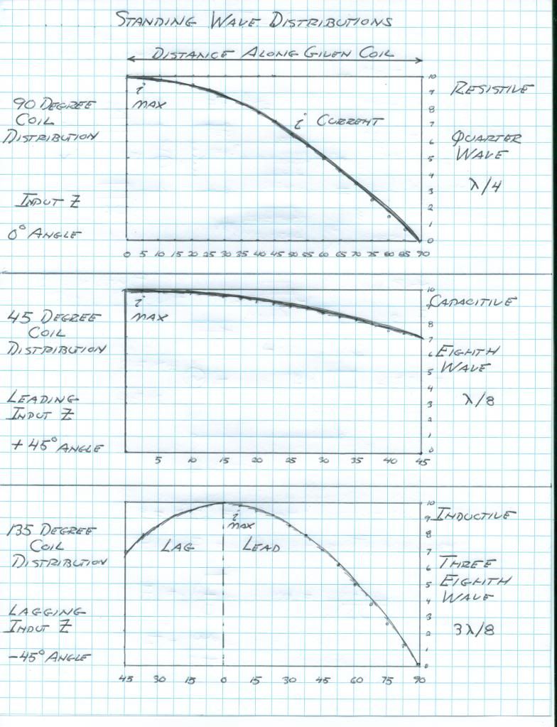
                        What does "lagging or leading input Z" mean in this diagram, and is this the only way of determining the coupling mode between the coils? Is there any way of controlling the coupling, or is it based on the tuning?


                        As I recently posted, when both the secondary and extra coil are tuned to approximately the same frequency tested alone (extra coil with direct connection), in Concatenated mode the secondary field intensity probe is unable to pick anything up. This happens with all three extra coils tested. This also approximately coincides with the highest potential and highest magnification factor. Does this sound right to you?


                        (Side note, these graphs are for the longer extra coil wire compensated for 119% direct connection velocity, Concatenated to Tandem ratio = 1.57)

                        I've also been wondering how relevant the field intensity actually is in Concatenated mode. If the transformer is working "properly", then shouldn't the field intensity be minimal, since the transmission/output (or input) terminal is the ground end, and this field would represent wasted energy? What about putting a meter between the secondary neutral and ground?

                        Anyway I've put all the data gathered on these coils so far here, but it has become a bit of a notebook and may contain some useless things

                        http://www.energeticforum.com/renewa...ompendium.html

                        Thank you, and I apologise for the blast of questions
                        Last edited by dR-Green; 11-23-2012, 11:32 PM.
                        http://www.teslascientific.com/

                        "Knowledge is cosmic. It does not evolve or unfold in man. Man unfolds to an awareness of it. He gradually discovers it." - Walter Russell

                        "Once men died for Truth, but now Truth dies at the hands of men." - Manly P. Hall

                        Comment


                        • Area52

                          Originally posted by T-rex View Post
                          I will be stuck in front of the internem for a few days so I can answer questions...
                          Hello Eric,

                          It is given by you that your 'AREA52' activities are classified, restricted, or on a need to know basis.

                          The E.F (forum) I gather, dosen't have the nessasary security clearance for these details; however can you give us any 'clues' about the said AREA52 activities?
                          "Doesn't matter how many times you kick the coyote in the head, it's still gonna eat chickens". - EPD

                          Comment


                          • Originally posted by Farmhand View Post
                            Hi dR, It looks to me like in you're concatenated mode you have a half wave
                            on the extra coil and maybe a bit more than a 1/4 wave on the secondary. I base
                            my opinion on the way there appears to be a 0 volt node in the center of the
                            extra coil and the voltage seems to drop off before the top of the secondary.
                            I don't know what's actually going on, but I finally assembled and tested an "RF Current Probe" from the ARRL Antenna Book, and the extra coil is not working properly I don't think. It shows the same pattern as the LEDs in the video but it's a lot more sensitive and easier to read. About half way up the extra coil the reading drops off completely, then reappears. The highest reading in the whole setup appears to be at the first turn (bottom) of the extra coil.

                            [edit] Although, there's a blank spot in the middle of the secondary too in Concatenated mode if I rotate the probing coil 180 degrees.

                            With the rotated probe, Tandem mode appears to have exactly the 1/4 wave current distribution in both coils like Eric's diagram above - highest reading at the bottom of the coils, and nothing at the top of each coil. Rotating the probe back to its original position, it seems to be measuring it in the same manner as the field intensity meter.
                            Last edited by dR-Green; 11-24-2012, 09:03 AM.
                            http://www.teslascientific.com/

                            "Knowledge is cosmic. It does not evolve or unfold in man. Man unfolds to an awareness of it. He gradually discovers it." - Walter Russell

                            "Once men died for Truth, but now Truth dies at the hands of men." - Manly P. Hall

                            Comment


                            • Ask Mr. Wizard the Lizard

                              Dr Green,

                              From your you tube video you have a HALF WAVE on your secondary and a three eigths wave on your extra coil. The exciting frequency is too high then as indicated by the space distribution with your probe, this a potential device. Neons are better than LED, or make a capacitance pickup for your oscilloscope. With oscillator on X axis and probe on Y axis you can measure phase shift. Read Vol II, Communication Networks, Introduction for distributed constants definition.

                              If your extra coil RAISES the secondary frequency, it is magnetic inductive and wire is too long. If it drops the secondary frequency it is dielectric capacitive and wire is too short on the extra coil. Note, you must have primary condenser on primary loop.

                              Also, place a RF milliammeter in neutral to ground connection for indication of Telluric output. The 6SN7 driver I gave in past can give you more power so as to light lamps.

                              73 DE N6KPH
                              Last edited by t-rex; 11-25-2012, 12:35 AM.
                              SUPPORT ERIC DOLLARD'S WORK AT EPD LABORATORIES, INC.

                              Purchase Eric Dollard's Books & Videos: Eric Dollard Books & Videos
                              Donate by Paypal: Donate to EPD Laboratories

                              Comment


                              • On a general note,
                                1) Do not ask about Area 52.
                                2) I write some on the Wardenclyffe "Science Center" thread that may be interesting.
                                3) The Wardenclyffe, Tesla True Intention thread is Bearden disinformation shill, or coyote puke.

                                73 DE N6KPH
                                SUPPORT ERIC DOLLARD'S WORK AT EPD LABORATORIES, INC.

                                Purchase Eric Dollard's Books & Videos: Eric Dollard Books & Videos
                                Donate by Paypal: Donate to EPD Laboratories

                                Comment

                                Working...
                                X