Announcement

Collapse
No announcement yet.

Eric Dollard

Collapse
This is a sticky topic.
X
X
 
  • Filter
  • Time
  • Show
Clear All
new posts

  • Sputins
    replied
    Originally posted by Ajay View Post
    I would imagine the easiest way to tune the extra coil is the way which Tesla used, which is adding an insulated and elevated capacity to it. To fine tune it, I believe Tesla raised his capacity in the air until the added elevation provided enough additional capacitance to resonate the coil. May I ask what kind of power supply/circuit interrupter you are using, Sputins?

    Here are some mediocre pictures of my set up. You can see the coils (which look like balls of tape) and the 50kv induction coil w/ door knob capacitors that I have been using.
    I am using my laptop camera to take the pictures, so I don't want to risk having my computer near the coil while it is in operation.
    The power source is currently two large 6v batteries hooked up and operating at a bout 8v and .5 amps, so there is significantly less power in the circuit than Tesla had with his high frequency alternators driving the coil.

    I would like to discuss the interrupter circuits that Eric has proposed over the years and there relation to Tesla's circuits. In the paper "Condensed Intro to Tesla Transformers", he discusses multipactor and vacuum tube drive as well as a negative resistance spark gap as a means for creating the proper oscillations in the primary. In the Borderlands video, they used two hydrogen spark gaps. Eric said that "the E.M.F is much greater by the spark method" in his Condensed Intro. Tesla used various types of spark gaps at regular atmospheric pressure, he said that vacuum tubes could be used but that he "encountered other difficulties" when using them. I have been using a powerful fan to blow out the spark in my hairpin circuit just as Tesla described in the London lecture and I have found it to be extremely difficult to tune. Are there any better alternatives using modern day tech?
    Ajay,
    Nice 50Kv induction coil you have there. You are probably just not achieving a resonant condition with the induction coil and its spark gap etc. What frequency do you expect it to work at or near?

    As for interrupter circuits, or driving circuits, etc. you have various options...

    I started my experiments as a young lad, mainly using audio amplifier’s together with an audio frequency generator. So this allows any frequency from 10Hz through to about 60Khz or whatever the actual cut off frequency of the audio amp is.

    A mono audio amp can be bought and made in a kit, design your own or buy off the shelf. I used mono car audio amps of around 100-300 watts or built my own. Couple the amp with an audio generator and you have a basic driver of variable frequency for driving coils and such. (But only up to about 40-60Khz).

    Spark gaps, like hydrogen 1B22 as Eric used years ago can work. Other rotary spark gaps etc. However the 1b22 is radioactive and is hard to find. I avoid spark gaps if possible because they can be noisy, hard to tune, with not much control over them. For brute force they are certainly fit for purpose…

    For the higher frequencies and precise control, you’ll want a Radio Frequency Amplifier. Build your own is best.
    Class A, Class AB, Class C or Class D amplifiers could be used. (Generally Class C for RF). You could use Transistors, Vacuum Tubes, Thyratrons or even Magnetic Amps.

    The Class type and design of an RF generator / amplifier is a complex subject...

    But you can build your own with some study. (Ham Radio is where to start). From a simple, low power device, through to some complex powerful monster. (Check the radio licence laws in your country etc.).

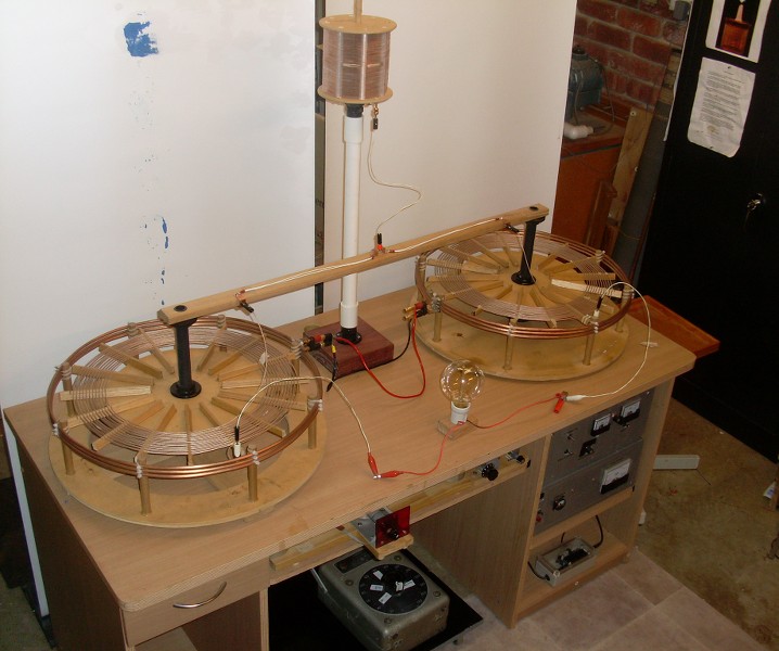
    My Rig uses a CW, AM Radio Transmitter using a 6AG7 two 807 Vacuum tubes in parallel. Frequency control is via a VFO (Variable Frequency Oscillator) within the 160m band. (Maximum power of 100 Watts). For basic tuning and resonance tests, I just use the VFO and a tiny transistorised amp of very low power.

    Hope some of that helps.
    Last edited by Sputins; 01-21-2016, 12:31 AM.

    Leave a comment:


  • Ajay
    replied
    Sputins Extra Coil and Tuning

    I would imagine the easiest way to tune the extra coil is the way which Tesla used, which is adding an insulated and elevated capacity to it. To fine tune it, I believe Tesla raised his capacity in the air until the added elevation provided enough additional capacitance to resonate the coil. May I ask what kind of power supply/circuit interrupter you are using, Sputins?

    Here are some mediocre pictures of my set up. You can see the coils (which look like balls of tape) and the 50kv induction coil w/ door knob capacitors that I have been using.
    I am using my laptop camera to take the pictures, so I don't want to risk having my computer near the coil while it is in operation.
    The power source is currently two large 6v batteries hooked up and operating at a bout 8v and .5 amps, so there is significantly less power in the circuit than Tesla had with his high frequency alternators driving the coil.

    I would like to discuss the interrupter circuits that Eric has proposed over the years and there relation to Tesla's circuits. In the paper "Condensed Intro to Tesla Transformers", he discusses multipactor and vacuum tube drive as well as a negative resistance spark gap as a means for creating the proper oscillations in the primary. In the Borderlands video, they used two hydrogen spark gaps. Eric said that "the E.M.F is much greater by the spark method" in his Condensed Intro. Tesla used various types of spark gaps at regular atmospheric pressure, he said that vacuum tubes could be used but that he "encountered other difficulties" when using them. I have been using a powerful fan to blow out the spark in my hairpin circuit just as Tesla described in the London lecture and I have found it to be extremely difficult to tune. Are there any better alternatives using modern day tech?
    Attached Files
    Last edited by Ajay; 01-20-2016, 05:41 PM.

    Leave a comment:


  • Sputins
    replied
    Originally posted by Ajay View Post
    Were you able to achieve resonance with that set up? It looks very nice. I would imagine that the extra coil would not work in that position unless both of the other ends of the secondary coils were sufficiently grounded to force the potential toward the center.
    Ajay,

    Tuning the coils is all part of the challenge. The two ends you suggest grounding, are actually the output ends. (Why I showed the globe across them). Sure, grounding these outputs may help the Extracoil to resinate, but certain resonant frequencies can still be found even when leaving it all “floating.”… Added capacity can help to shuttle currents this way or that way. Although during certain Ro frequency sweeps I do ground the outputs when required.

    Analysing and optimising the rigs resonance point(s) is indeed quite challenging. The Extra coil certainly complicates matters. The rig though will easily perform the monopole electrical transformation without any Extracoil added at all.

    I have some new equipment on the way, which should help with the Ro frequency sweeps.

    Good luck with your coil replication, post some working photos if you are able.

    Leave a comment:


  • Ajay
    replied
    Bucking Tesla Resonant Induction Coil

    Hello,
    I have finished the construction of my first bucking resonant induction coil based on the coil that was in Tesla's London lecture. I have attached the basic coil layout and circuit diagram that I got from the lecture.
    It is not a true replication because I did not use gutta percha wire in beeswax impregnated paper insulation, however, I calculated that the primary and secondary are the same surface area and it is wound in the same "bucking" configuration. Based on previous math, it seems Tesla's induction coil did not keep the surface area a constant between primary and secondary, so perhaps I will rewind the secondary for more turns.
    It was difficult to tune, and it is still not operating with a voltage node on the terminals of the secondary (as it should be). The main reason for this is the difficulty of tuning a spark gap system as well as the fact that the bucking coils seem to cancel out electromagnetic induction. I can not even light an LED on the secondary by scanning for resonance using a function generator @ 20vpp.
    However, using the spark gap "hairpin" circuit, I was able to draw (depressingly) small sparks off of the secondary that are brilliantly white in color and very loud. This shows me that a disruptive discharge certainly gives rise to "electrostatic" effects.
    The construction of my coil is as follows:
    Primary - 2X 3 layers of 14 AWG, 7 turns per layer for a total of 15.5 ft and 42 turns. (25 uH)
    Secondary -2X 2 layers of 24 AWG magnet wire, 26 turns per layer for a total of 55.5 ft and 104 turns
    Power Source - 50kv induction coil driven by a 9v battery
    The primary is wound inside the secondary as is shown in Tesla's split coil diagram. It can be seen in his diagram that he used significantly more turns then I did. I wanted to create one like this, but it is very difficult to accurately measure the length of such a long wire, especially because the coil diameter changes with each layer. Both my primary and secondary are one piece of wire in my coil, which is not easy to do when constructing a multi layered bucking coil transformer!
    I will be messing around with the insulated capacitance on the secondary to see if I can get a stable and sharp resonance between the two coils. If I get any decent sparks, I will upload photos. My goal is to create a coil which exhibits biological effects like the shockwaves and heat which Tesla referred to.
    Attached Files
    Last edited by Ajay; 01-16-2016, 04:11 PM.

    Leave a comment:


  • Ajay
    replied
    Originally posted by Sputins View Post
    There has been further progress since the photos.
    Were you able to achieve resonance with that set up? It looks very nice. I would imagine that the extra coil would not work in that position unless both of the other ends of the secondary coils were sufficiently grounded to force the potential toward the center.

    Leave a comment:


  • Sputins
    replied
    Activity early 2016

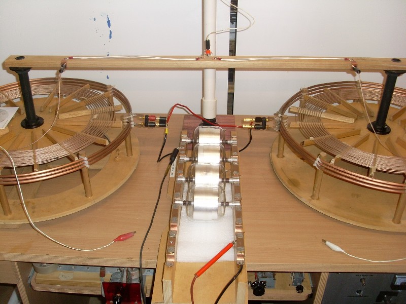
    I have temporarily set up my small rig in an old PC desk so that the transmitter is safely housed and provides more bench top space. Below are the two coils in Electrostatic configuration, direct connected to a single Extracoil. I’m also constructing a two-way variable capacitive coupling arrangement for this among other things. Screens provide some privacy.


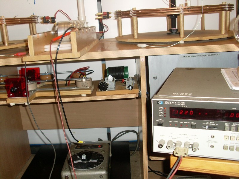
    Lower shelves pull out for access:


    I was considering the use of these vacuum capacitors for the main tank C. (Pulled from an old sparking VTTC, built many years ago):


    Capacitance measured with a 4262A HP LCR Meter. (Glom score for $25, normally several hundred):


    There has been further progress since the photos.

    Leave a comment:


  • Sputins
    replied
    Pics and Video

    Originally posted by Aaron View Post
    Advanced Seismic Warning System Transmission Lines

    December 29, 2015

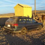
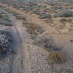
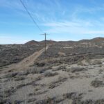
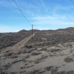
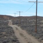
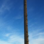
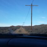
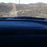
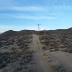
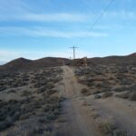
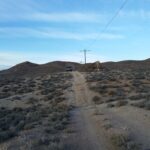
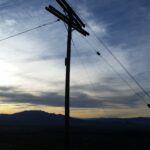
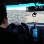
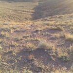
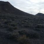
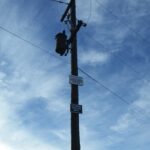
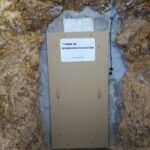
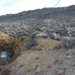
    Here is a set of pictures where I (Aaron Murakami) drove with Eric Dollard and Stephen McGreevy up to the transmission line site. The transmission lines are about 1.25 miles long, which makes this the largest scale Tesla-Alexanderson type transmission project in the world.

    Part of the lines run adjacent to some power lines, which may cause interference so EPD Laboratories, Inc. may only use part of the lines.
    We also drive up to an old seismic mine, which is now under the control of EPD Laboratories, Inc. There are 2 highly sophisticated seismographs, which will be used as part of the data to predict earthquakes 6.0 and above 48-72 hours ahead of time. The other 3 pieces of data is solar flux activity and above and below ground signals, which the transmission structure will receive.

    A video will be coming soon explaining in detail what you see in the pictures below. It was very windy so some of the audio is hard to hear, but it will be left in the video so you get the raw uncut version.
    Thanks for the great pictures and videos Aaron. I’ve really enjoyed them all. I’m sure it was a great trip.

    The scope of the project and the work involved with the whole deal is unbelievable.

    It was good to see Stephen McGreevy go along for the ride and experience it all as well. I’m sure he would have become enthused by the whole project. It aligns nicely with some of the interests he has. (I should hurry up and finish off building one of Stephen’s VLF receivers I started to make awhile back).

    The Extraluminal Analog Networks video with the scope provides the teaching not found anywhere else!

    Fantastic stuff indeed

    Leave a comment:


  • BroMikey
    replied
    Originally posted by Aaron View Post
    Here are pics of Eric's recent Transverse & Longitudinal analog network experiments:
    I am very impressed ERIC. The time is now for us to learn all
    we can from you. We all love you even tho you can be hard on
    us sometimes. You are a great man. I don't say that lightly
    either, trust me.

    These pictures have inspired me all over again and I am expecting
    you to show us something that is beyond all of the others.
    I know you are waiting for the right time.

    You are one of the best thinkers of all time. Stick with him Aaron
    you guys are super intellects.

    What can I say, you guys are making my day. I am excited about
    what's coming down the road with your work guys. It's only now
    that many of us who are just learning are realizing what the new
    forms of energy are all about.

    Thanks to guys like you Eric.

    Some of these younger guys need to get a book and read it. That
    should help them and you, to accelerate their learning on the subject.

    T-Rex is at it again. That shovel is a bunch of work.
    Last edited by BroMikey; 01-14-2016, 07:16 AM.

    Leave a comment:


  • Aaron
    replied
    Stephen P. McGreevy Interview

    Earth Radio Interview with Stephen P. McGreevy

    January 7, 2016
    Natural VLF Radio Stephen P. McGreevy of Auroral Chorus came over to EPD Laboratories early December to meet with us to see the latest on Dollard’s semismic lines and we had time to do an interview with him. Stephen presented at the last Energy Conference on Natural VLF Radio, which was his journey around the world capturing the natural sounds that nature produces, which are able to be heard on his specialized receivers. His presentation is here: http://naturalvlfradio.com


    Here is an interview with Stephen at EPD Laboratories, Inc.


    Support Stephen P. McGreevy’s work by getting your own Natural VLF Radio receiver at auroralchorus.com - Natural VLF Radio - Sounds of Space Weather - The Music of the Magnetosphere


    [VIDEO]https://www.youtube.com/watch?v=Xag1EW2xq0k[/VIDEO]

    Leave a comment:


  • Aaron
    replied
    Transmission lines video

    Video of Transmission Lines

    January 5, 2016


    Here is a video that goes to these pictures: http://ericpdollard.com/2015/12/29/a...mission-lines/


    There is a LOT of wind in some parts so some audio is not audible, but it is all left in the video to make it complete.


    There are more videos and pictures of my (Aaron) recent trip to Eric Dollard’s lab and the rest have really good audio so stay tuned… in the meantime, watch this:


    [VIDEO]https://www.youtube.com/watch?v=hgSzsLiKRqQ[/VIDEO]


    Make sure to come meet Eric Dollard at the 2016 Energy Science & Technology Conference – register now Home - 2016 Energy Science & Technology Conference

    Leave a comment:


  • dR-Green
    replied
    Originally posted by Aaron View Post
    Extraluminal Analog Network Video Presentation

    January 13, 2016
    Here is a video presentation of Eric Dollard showing his recent bench experiments with analog networks that demonstrate both transverse and longitudinal propagation. When used together, time is cancelled out of the equation so that information can transmit from one end of the system to the other with no time delay. That isn’t faster than the speed of light, it is instantaneous or extraluminal.
    Excellent demonstration and explanation. Thanks!

    Leave a comment:


  • Aaron
    replied
    pics 4


    Leave a comment:


  • Aaron
    replied
    pics 3


    Leave a comment:


  • Aaron
    replied
    pics 2


    Leave a comment:


  • Aaron
    replied
    the pics 1


    Leave a comment:

Working...
X