Advanced Seismic Warning System Transmission Lines
Advanced Seismic Warning System Transmission Lines
December 29, 2015
Here is a set of pictures where I (Aaron Murakami) drove with Eric Dollard and Stephen McGreevy up to the transmission line site. The transmission lines are about 1.25 miles long, which makes this the largest scale Tesla-Alexanderson type transmission project in the world.
Part of the lines run adjacent to some power lines, which may cause interference so EPD Laboratories, Inc. may only use part of the lines.
We also drive up to an old seismic mine, which is now under the control of EPD Laboratories, Inc. There are 2 highly sophisticated seismographs, which will be used as part of the data to predict earthquakes 6.0 and above 48-72 hours ahead of time. The other 3 pieces of data is solar flux activity and above and below ground signals, which the transmission structure will receive.
A video will be coming soon explaining in detail what you see in the pictures below. It was very windy so some of the audio is hard to hear, but it will be left in the video so you get the raw uncut version.
Announcement
Collapse
No announcement yet.
Eric Dollard
Collapse
This is a sticky topic.
X
X
-
Extraluminal Analog Network Video Presentation
Extraluminal Analog Network Video Presentation
January 13, 2016
Here is a video presentation of Eric Dollard showing his recent bench experiments with analog networks that demonstrate both transverse and longitudinal propagation. When used together, time is cancelled out of the equation so that information can transmit from one end of the system to the other with no time delay. That isn’t faster than the speed of light, it is instantaneous or extraluminal.
[VIDEO]https://www.youtube.com/watch?v=bi0wg3UvSSw[/VIDEO]
Leave a comment:
-
Transverse & Longitudinal Analog Networks
Here are pics of Eric's recent Transverse & Longitudinal analog network experiments: Transverse & Longitudinal Analog Networks - Eric P. Dollard - Official Homepage
Transverse & Longitudinal Analog Networks
January 9, 2016
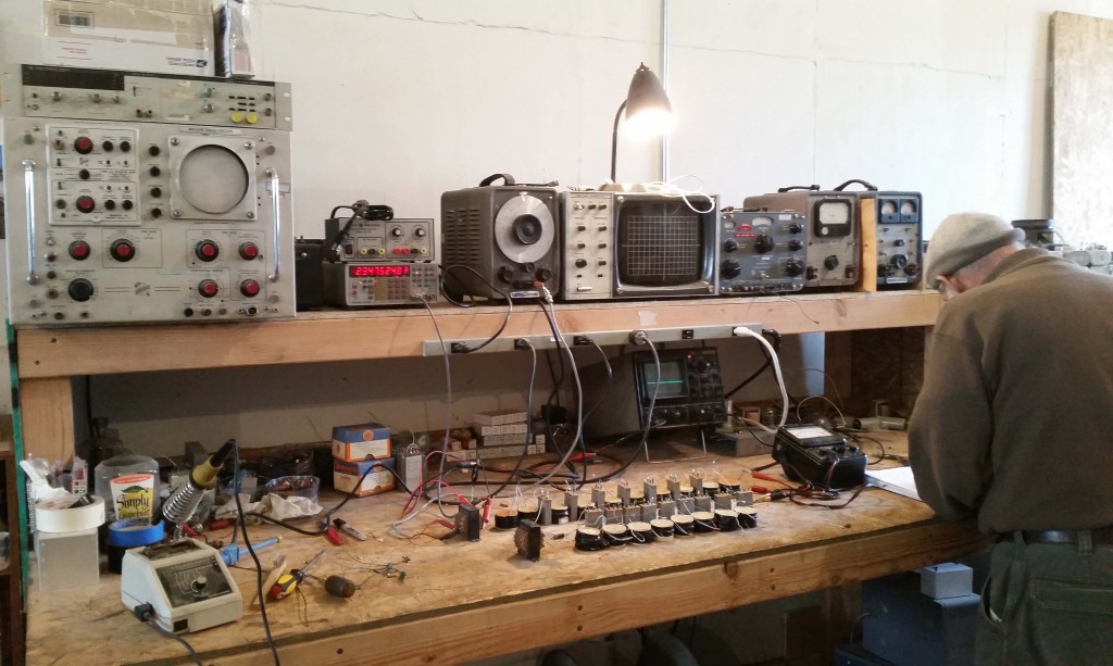
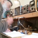
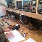
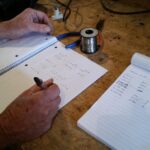
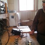
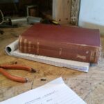
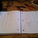
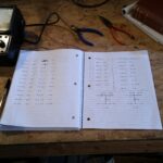
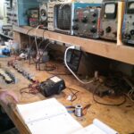
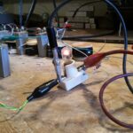
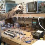
Here are photographs from a recent visit to EPD Laboratories, Inc. showing Eric Dollard working on some Transverse & Longitudinal Analog Networks, which cancel time out of the equation on transmission lines when used together. That means that signals can propagate from end of the transmission structure (lines) to another without any time delay. That isn’t faster than the speed of light since there is no velocity, it is instantaneous, which is extraluminal.
A new video walk through by Eric Dollard is coming soon that will explain what you see in the pictures below.
If you want to see the classic Borderland videos on this exact topic, watch these free presentations here: Transverse & Longitudinal Electric Waves and Tesla's Longitudinal Electricity - Eric P. Dollard - Official Homepage
Leave a comment:
-
But what you have done SIR is to sum this all up in a nut shall
without all of the fast talk and super shiny math to dazzle.
Oh I can do the Math no problem, Calculus was no harder than add
and subtract, just a process of continued learning.
I like your delivery best, it is straight to the point without distraction
as you say, for this I am very grateful.
See when I was little I was placed into a hell
that created a learning problem while in grade school.
After that I became a super student all through school an honor roll
student and high grades in college. If an instructor was a dink I got up
and left never coming back. I don't care about money or who thinks
I should be made into something they want.
That's just the way it is.
I thank you for the simple run down, just as pure as the snow.
The tinkering is probably where we all start and the big thing
about why I am here is that I feel many diagrams do not give
a clear indication of how the math works out on the mass of the
copper and the other needed calculations.
The problem is that many have built these with only an approximate
close enough for horseshoes style of rig. This is what has stopped me
for all of these years. Oh I have whipped up a good many coil sets
at random also without understanding any of the experiments you
pointed out.
ERIC has been so far above everyone for most of his life that they
could not always understand him. It has taken time to distill what he
knows, down so that the rest of us may catch on.
In other words ERIC must teach and that is a hard job. I have watched
Eric for years in his talks and conference meetings and even his closest
friends do not understand what he is talking about all of the time.
ERIC will ask a question and no one has the answer, so he answers.
I am glad for this higher thinking, glad to listen and happy to know
someone can go beyond the conventional wisdom, not being afraid
of what others may think of him.
Eric you are a great man.
Now Sputins, with what you have given me in a nut shall I can google
to find out who has done each of these tests that were offered in
popular science as far back as the 50's. Today the youtube guys are
much more advanced.
Your KEY WORDS will help me to study, to pick out what each effect
might do as shown by the video.
I am slow, but always start by watching others examples first. Now
thanks to you I will find some of the work related to these apparatus.
I see you have done your home work over the years Sputins and this
is why I accept your direction with joy Last edited by BroMikey; 01-21-2016, 03:06 AM.
Leave a comment:
-
We’ll everyone’s goal for a Tesla coil system is likely different.Originally posted by BroMikey View Post
Still it seems like after some 15 -20 years on the web a
simple statement of what the goals are would help people
so as to get a starting point into the work.
I am sure that the goals are stated somewhere so I will keep
reading. When I find out what the goals specifically are, then
I will be able to decide if this is practical or just learning
fun used as some sort of stepping stone to a real device that
can be utilized in some way.
Not everyone can answer this question I guess.
I have listened to ERIC endless hours and hours and hours and
hours and watched videos of many experiments. I saw him go
out on the beach with one and collect the energy he was sending
from miles away.
Is that what this is? A proof that longitudinal waves exist?
Tesla’s original purpose is to transmit power, via a mono-polar electrical transmission system. I.e. using the Earth as the single conductor for a communication and power transmission system. Exact quotes from Tesla could be inserted here.
While the TMT isn’t an overunity device of itself, it may be found that upon utilising certain resonant frequencies of the Earth itself the TMT mono-polar telluric currents may allow a “coupling” with naturally existing earth currents that the TMT system might tap into and draw upon…
 That would be the ultimate goal, a new source of energy via taping into the natural telluric currents of the Earth.
For us simple plebs, likely power transmission via the earth is limited. Even more unlikely is drawing the extra power out via of the Earth itself unless you’ve invested in some serious apparatus to do so.
However there are secondary goals of value:
 One might build the CRI* to learn about and discover (telluric) radio wave reception via the ground and general coil construction and tuning methods. (This knowledge may eventually lead to the greater overall understanding).
 Small TMT’s can be constructed so that one might attempt to transmit signals, data or limited power via a single conductor through the natural or unnatural media.
 One might attempt to explore the effects of the intermixing of dielectric flux, I.e. the “Galaxy in a Light-bulb” concept.
 One might discover something new or long since forgotten concerning the mono-polar forms of electricity.
 One might even look into the more exotic concepts that Eric hints at with the work of JJ Thompson…
 Perhaps some people just want to simply tinker and experiment in their garage?
The limit is only found given one’s available time, ability, money, imagination and determination. (**Oh and ability to manage life’s distractions).
*The CRI Crystal Radio Initiative is actually very clever. It is an Initiative. What this does in teaches the construction and principals behind the TMT, without the need for a radio licence etc. because it is a receiver only. It is a place for a beginner to start and learn. It does seem like a big expense and effort to light up a small bulb, but that isn’t the whole point. - The point is that it teaches you how and proves Tesla’s monopolar earth transmission concept.
** One cannot always prevent distractions, or perhaps it’s just easier to play computer games or watch TV. - I adopt what I call my “One Hole Principal”. Meaning that if you have to deal with distractions or other commitments, just drill one hole. The principle of just drilling one hole, or attaching one screw, or complete one simple task to your project per day or per unit interval, then it is a small step forward…
Sputins.Last edited by Sputins; 01-13-2016, 02:23 AM.
Leave a comment:
-
Thank you!Originally posted by Sputins View PostHi Ajay,
The Tesla multilayered coil transformer [bucking] is indeed one of the first iterations of the Tesla Transformer, it is a resonant induction coil. You could build one similar with all the effects. - Because of the large inductance together with the self-capacity, Tesla’s [London] induction transformer would likely have a much lower frequency than that of the Crystal Radio Initiative or TMT’s based on Eric’s design criteria.
The Crystal Radio Initiative or TMT’s using Eric’s design criteria are related to the Tesla’s Colorado Springs Transformer, not based on the “London Coil” as it were. Of course their general operation, general configuration and effects are similar. But you can’t have a multilayered [London] coil with 62% spacing!
Also the Eric’s CRI and TMT are designed for a specific Frequency, MW AM band for CRI and the TMT’s frequency is more freelance, but Eric’s idea is to utilise the 160M ham radio band, provided one is licenced for that. [1860Kc being Eric’s Magic Telluric band].
What do you mean exactly by “disruptive discharge circuit”? You wouldn’t want to operate a spark gap system on any ham band, (for long) or likely authorities from the FCC will hunt you down and tear you a new one, after complaints from other hams. So study ham radio and build yourself a CW, AM Radio Transmitter for the desired band.
You might get away with operating a spark gap London-style coil with a spark gap as it would likely be on the LF or VLF band, (below 300Khz)… Check your local radio frequency spectrum allocation chart…
Looking forward to seeing posts of your work.
I almost forgot about the damn FCC. I am indeed referring to a Tesla type spark gap disruptive discharge circuit, so I will need to build myself a Faraday cage as well.
I am hoping to play around with the resonant frequency and see what kind of effects can be produced, so I don't want any restraints.
There is not an established way to tune the thing mathematically, so I have no clue if it will work, but I will certainly try!
I will keep the thread updated. Cheers,
Ajay
Leave a comment:
-
http://www.energeticforum.com/203209-post49.html
http://www.energeticforum.com/203210-post50.html
http://www.energeticforum.com/203354-post55.html
Thanks Sputins, I guess this is the answer.Originally posted by Sputins View Post
The Tesla multilayered coil transformer [bucking] is indeed one of the first iterations of the Tesla Transformer, it is a resonant induction coil. You could build one similar with all the effects. - Because of the large inductance together with the self-capacity, Tesla’s [London] induction transformer would likely have a much lower frequency than that of the Crystal Radio Initiative or TMT’s based on Eric’s design criteria.
The Crystal Radio Initiative or TMT’s using Eric’s design criteria are related to the Tesla’s Colorado Springs Transformer, not based on the “London Coil” as it were. Of course their general operation, general configuration and effects are similar. But you can’t have a multilayered [London] coil with 62% spacing!
Also the Eric’s CRI and TMT are designed for a specific Frequency, MW AM band for CRI and the TMT’s frequency is more freelance, but Eric’s idea is to utilise the 160M ham radio band, provided one is licenced for that. [1860Kc being Eric’s Magic Telluric band].
What do you mean exactly by “disruptive discharge circuit”? You wouldn’t want to operate a spark gap system on any ham band, (for long) or likely authorities from the FCC will hunt you down and tear you a new one, after complaints from other hams. So study ham radio and build yourself a CW, AM Radio Transmitter for the desired band.
You might get away with operating a spark gap London-style coil with a spark gap as it would likely be on the LF or VLF band, (below 300Khz)… Check your local radio frequency spectrum allocation chart…
Looking forward to seeing posts of your work.
Seems like I saw some 6 foot ones ever since the web
started.
Anyone else? Got something to say about what the goals are?
I will keep reading. I guess it's time to google it. Generally when
I do that I get either Myth busters or OVERUNITY.
Still it seems like after some 15 -20 years on the web a
simple statement of what the goals are would help people
so as to get a starting point into the work.
I am sure that the goals are stated somewhere so I will keep
reading. When I find out what the goals specifically are, then
I will be able to decide if this is practical or just learning
fun used as some sort of stepping stone to a real device that
can be utilized in some way.
Not everyone can answer this question I guess.
I have listened to ERIC endless hours and hours and hours and
hours and watched videos of many experiments. I saw him go
out on the beach with one and collect the energy he was sending
from miles away.
Is that what this is? A proof that longitudinal waves exist?
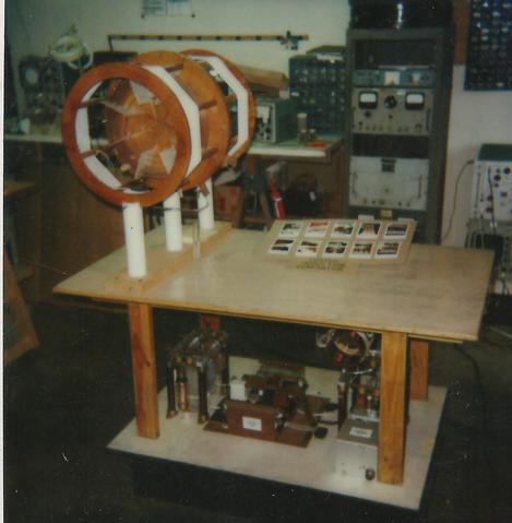
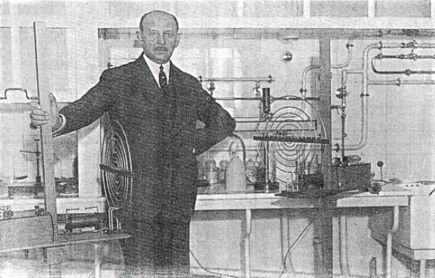
Index of /Tesla_Tri-Metal_Generator

Originally posted by t-rex View PostThere is no Poynting Vector on a resonant transformer - it is cancelled out.
Electromagnetic relations cannot be utilized in this situation.
There is no velocity in space. The velocity is in counter space in per cm per second.
73 DE N6KPH
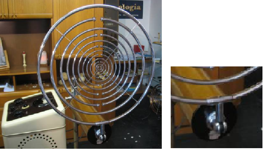


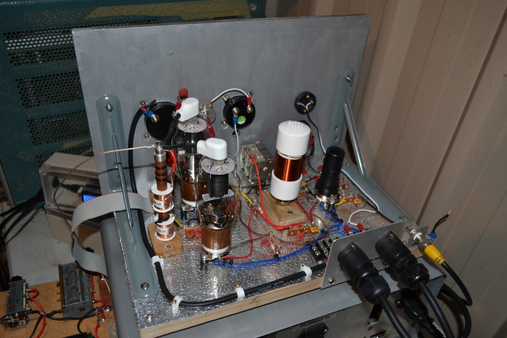 Last edited by BroMikey; 01-12-2016, 03:55 AM.
Leave a comment:
-
Hi Ajay,Originally posted by Ajay View PostHello,
I am attempting to build a Tesla Magnifying Transmitter using the mathematics that Eric provided for the Crystal Radio Initiative. However, I am going to attempt to build it using the Tesla disruptive discharge circuit (driven at 50kv from an induction coil) and two Tesla transformers connected in a bucking configuration (a.k.a Cosmic Induction Generator). The reason that I am building it like this this is to contain the dielectric flux between the terminals of the secondary.
I am struggling with the construction of this coil, however. In Tesla's lecture on High Frequency in London, he described a multi layered bucking coil transformer that is very similar to the Cosmic Induction Transformer. In the Alexanderson system presentation, Eric described this induction coil as one of the first iterations of the Tesla Transformer, and he also called it the perfected induction coil.
How would I go about tuning such a coil? Spacing the turns by 62% seems nearly impossible with such a coil due to the multiple layers. Would each half of the secondary (oppositely wound) act independently as a quarter wave resonator as in the Cosmic Induction Generator? Or would I want the total length of the secondary to be 1/4 wave length?
The Tesla multilayered coil transformer [bucking] is indeed one of the first iterations of the Tesla Transformer, it is a resonant induction coil. You could build one similar with all the effects. - Because of the large inductance together with the self-capacity, Tesla’s [London] induction transformer would likely have a much lower frequency than that of the Crystal Radio Initiative or TMT’s based on Eric’s design criteria.
The Crystal Radio Initiative or TMT’s using Eric’s design criteria are related to the Tesla’s Colorado Springs Transformer, not based on the “London Coil” as it were. Of course their general operation, general configuration and effects are similar. But you can’t have a multilayered [London] coil with 62% spacing!
Also the Eric’s CRI and TMT are designed for a specific Frequency, MW AM band for CRI and the TMT’s frequency is more freelance, but Eric’s idea is to utilise the 160M ham radio band, provided one is licenced for that. [1860Kc being Eric’s Magic Telluric band].
What do you mean exactly by “disruptive discharge circuit”? You wouldn’t want to operate a spark gap system on any ham band, (for long) or likely authorities from the FCC will hunt you down and tear you a new one, after complaints from other hams. So study ham radio and build yourself a CW, AM Radio Transmitter for the desired band.
You might get away with operating a spark gap London-style coil with a spark gap as it would likely be on the LF or VLF band, (below 300Khz)… Check your local radio frequency spectrum allocation chart…
Looking forward to seeing posts of your work.
Leave a comment:
-
Thanks Dr. Green & Aaron for a nice clean cut.Originally posted by Aaron View PostHe stated clearly in this thread before that he is not interested in learning about anything in this thread, literally, yet he demands proof of something he can't comprehend and doesn't even know what he is asking for.
Besides, I booted him for his mouth going overboard for way too long.
@Green
Don't let any of these back stabbers kill your desire to build, I
really am enjoying this experiment, mainly because I have always
wanted to build one. I just never knew what it did or what it is for.
Now I THINK I know, it is for producing HV Plasma to do HV experiments
and I think that you need 2 of them. One to transmit and one to
receive, but this is only what I think. I read and read these posts
and I speak English and still I am not sure of the end goal.
I look forward to some day understanding what this build does so
I watch and read and wonder.
Thanks for your diagrams and pictures. To each his own on his way
to learning what this stuff does and definitely lay the axe to people
who show nothing but hate.
Also, so far I think this is an experiment in how to create a 1/4 wave
resonant pump? Like any Tesla coil, right? It may seem like dumb
question so if you decide not to answer, I will understand.
Sign, watching and wondering.Last edited by BroMikey; 01-12-2016, 02:40 AM.
Leave a comment:
-
Cosmic Induction Generator tuning and coonstruction
Hello,
I am attempting to build a Tesla Magnifying Transmitter using the mathematics that Eric provided for the Crystal Radio Initiative. However, I am going to attempt to build it using the Tesla disruptive discharge circuit (driven at 50kv from an induction coil) and two Tesla transformers connected in a bucking configuration (a.k.a Cosmic Induction Generator). The reason that I am building it like this this is to contain the dielectric flux between the terminals of the secondary.
I am struggling with the construction of this coil, however. In Tesla's lecture on High Frequency in London, he described a multi layered bucking coil transformer that is very similar to the Cosmic Induction Transformer. In the Alexanderson system presentation, Eric described this induction coil as one of the first iterations of the Tesla Transformer, and he also called it the perfected induction coil.
How would I go about tuning such a coil? Spacing the turns by 62% seems nearly impossible with such a coil due to the multiple layers. Would each half of the secondary (oppositely wound) act independently as a quarter wave resonator as in the Cosmic Induction Generator? Or would I want the total length of the secondary to be 1/4 wave length?
Leave a comment:
-
banned
He stated clearly in this thread before that he is not interested in learning about anything in this thread, literally, yet he demands proof of something he can't comprehend and doesn't even know what he is asking for.Originally posted by dR-Green View PostShow what you are talking about through building something that works. All I see from you is Swastika Swastika Swastika. It means nothing to me. Build it or stop distracting.
Besides, I booted him for his mouth going overboard for way too long.
Leave a comment:
-
I don't know what the Swastika has to do with a fire drill and a picture of a boy trying to start a fire. I play with sticks out in the bushes tooOriginally posted by Raphael37 View Post^^^ your 'plates' depict the same geometry studied as B-mode and E-mode gravity waves linked to a simple idea lost on folks lost in space time unable to see bigger pictures linked by similar concepts...
Clearly the swastika is a tool that can be used to bend/polarize light.
P.S. NOW if Eric the guru was as smart as he claims, he would see the obvious too, and instead of ignoring the swastika, he would apply potential swastika insights to his work in order to make himself useful and take his genius to the next level of AHA

My coil design is that way for no reason whatsoever other than the fact it was most convenient to design it that way. I wouldn't look into it too much, and I certainly wouldn't draw any conclusions from it. I can just as well make any other shape except it would take more time and hassle to mark the wood. Fortunately a compass set to a certain size gives the correct dimensions from any central point without having to make any adjustments to the compass. That is design convenience.
Also I don't buy religious nonsense and the idea that we need to be redeemed. Speak for yourself.
Show what you are talking about through building something that works. All I see from you is Swastika Swastika Swastika. It means nothing to me. Build it or stop distracting.
Leave a comment:
-
you see here is another confirmation that it is time that ye tinkersOriginally posted by dR-Green View Post

 merged your work with a thinker


^^^ your 'plates' depict the same geometry studied as B-mode and E-mode gravity waves linked to a simple idea lost on folks lost in space time unable to see bigger pictures linked by similar concepts...
https://at37.wordpress.com/2012/03/2...-the-swastika/
^^^ Did ya get that Aaron?
I love popping off at the mouth when I AM correct
Clearly the swastika is a tool that can be used to bend/polarize light.

^^^ Clearly the swastika linked to the two fire sticks of Agni is a contender for the idea that was stolen from the gods linked to the gift of fire.
Clearly Aaron ye are out of touch with ME+me mystic reality.
selah V

P.S. NOW if Eric the guru was as smart as he claims, he would see the obvious too, and instead of ignoring the swastika, he would apply potential swastika insights to his work in order to make himself useful and take his genius to the next level of AHALast edited by Raphael37; 01-04-2016, 05:18 PM.
Leave a comment:
-
I do not need to relive every experiment Aaron.Originally posted by Aaron View PostIgnores 100% of every experiment here and elsewhere thereby magnifying his own desire to mislead people with his lies.
Just search "Ralph Wedekind", firefighter, swastika and you'll see countless examples of delusions of grandeur claiming he has been endowed with magical powers evidenced by the numbers of his firefighter badge and more. He calls himself the Swastika Sage of the Age.
He has already been banned from countless forums and I'm going to ban him here the next time he pops off at the mouth.
You however need to take your blah blah blah beyond the experimental stage and show me real world APPLICATIONS.
you and me cannot agree on what a viable APPLICATION is for all of your blah blah blah dude.
What page are we one here in this Eric Dullard thread?
And ALL I ask is go back and summarize ALL of the APPS for your guru Eric's work?
APPS not promises promises promises is ALL that I ask.
Yes it is true that I have been banned from countless forums.
500+ years ago Aaron, fellas like you would have called the Pope and ratted me out ranting and raving like I do ... in fact I promote the same geometry as Giordano Bruno!
dude it appears that your trump card is to call for an inquisition because I challenge your belief?
I have said nothing offensive on this forum other than point out the obvious to those like yourself blind to what is in plain sight.
I am glad that you are now helping me promote my epiphany.
https://at37.wordpress.com/?s=epiphany+of+raphael
Yes Aaron I admit I had an epiphany that left me ... a mystic?
No Aaron you are lying though IF you claim that I claim to have magical powers. I have never ever claimed to have magical powers.
Tell me why do the ignorant need to make false claims to score points?
Have you ever considered politics Aaron?
In fact I do not even endorse pursuing such folly to garner fame, lying.
But I do claim an insight granted to me by studying the swastika.
https://at37.wordpress.com/2013/03/2...riend-of-mine/
^^^ And my favorite Jewish mystic Itzhak Bentov supports this view too.
What is your problem Aaron?
'Putting all of your apples into the Eric Dollard Pi-in-the-sky basket' will not serve you well in the nano realm where the swastika reigns supreme.
It is obvious that a frank discussion about the swastika/s coupled with nano science and a tool to understand what gravity and entanglement is ...
... is obviously way over your head Aaron and maybe your guru Eric too?
Go back to selling books and making promises promises promises about saving countless lives predicting earthquakes ...
You really do like to ignore my last post where I linked great minds like Rene Schwaller and Itzhak Bentov to an idea that seems eternal?
Why?
https://at37.wordpress.com/2012/10/1...etic-swastika/
^^^ The MASTER BUILDER GRID can be shown to be linked to the spiral ramp theory that Jean Pierre Houdin proposes for the Great Pyramid too?
And I am surprised you have not banned me from this forum after the tongue lashing I gave you on your YouTube channel.
Go ahead
ban me dude
only somebody ignorant would bet against the 12,000+ year old swastika good luck charm capable of polarizing light as being a non-player in the grand scheme of things ... Last edited by Raphael37; 01-04-2016, 04:52 PM.
Leave a comment:
-
New Year 2016.
Indeed Happy New Year to all the EGF crew. Here we go for 2016, who knows what it might bring.
I spent the first nice, warm sunny day of the New Year tinkering with my spiral TMT rig. My new workshop (while somewhat cluttered) is operational. I’ve been re-configuring my current rig and have built it all into an old PC work bench where the transmitter is built in for safety and for space saving reasons. The top of the desk has the coils in various configurations.
The coils have been reconfigured at the moment, so I have the two primary coils connected in parallel, being driven from the transmitter & Pi network. The two secondary coils converge together driving one extra coil, similar to the “Statically Charged TMT” as seen within the Leyland Anderson’s “Rare notes”. So it will be fun to see if I can determine any significant differences here?

Certainly, at least the extra coil will be driven with more electrical energy as the two powered secondary coils permit more electrical flux into the system.
To follow will be a new extra coil, new Pi Network, new tank capacitor arrangement and other small tweeks to the overall system.
Photos to come when my internet is working properly.
@ Aaron - Looking forward to the news from EPD Laboratories!Originally posted by Aaron View PostTook many gigs of vids and pics at Eric's lab when I was on my trip. Will get the vids, etc. together as time permits:
All the best, Sputins.
Leave a comment:
Leave a comment: