Announcement

Collapse
No announcement yet.

Eric Dollard

Collapse
This is a sticky topic.
X
X
 
  • Filter
  • Time
  • Show
Clear All
new posts

  • #31
    Doc,
    Thanks for taking the time to explain it but I'm still confused. I thought we were tuning for a wave of the same frequency as the luminal wave but the velocity/wavelength of the two waves is different. From what your talking about it seems your implying different frequencies. Does this mean that the AM transmitter actually emits two waves of two differing frequency/velocity/wavelength rather than just two waves of two differing velocities. It seems in my line of reasoning I kept frequency constant but you made it variable. This also doesn't clear up the whole 2/pi 1/2pi problem either with the secondary coil length either. Could you also explain this statement more for me; "The extra coil would then need to operate at a minimum of 124% with no terminal capacitance." Sorry if my questions are silly, I'm still quite new to this TMT scheme. My sole focus for quite some time was on the 'free energy' aspects of this so I'm still trying to play catch up in certain parts.

    I should probably just do what I was originally going to do and build it from Eric's math and see how my understanding comes along from there because you're getting results so something interesting is going on.

    Raui
    Scribd account; http://www.scribd.com/raui

    Comment


    • #32
      Originally posted by Raui View Post
      Could you also explain this statement more for me; "The extra coil would then need to operate at a minimum of 124% with no terminal capacitance."
      By that I mean, it would not be possible to get it into resonance unless you used no terminal capacitance, and got the extra coil velocity to 124% minimum. Otherwise its frequency would be too low relative to the secondary.

      The frequency is constant. But if you take a 124% velocity in the way you mean and figure out the wavelengths from that, then all the numbers are still the same. IE replace c with the 124% value, do the calculations again, and you're back where you started.

      I see what you're getting at but I think the problem with treating it as a physical object moving through space from point A to point B is that it throws off the method of energising it in the first place, you'd just be making the frequency lower while the 124% measured velocity remains constant. You're increasing the distance between point A and point B so now while you're still travelling at 124% you won't make it in time. Or something like that
      Last edited by dR-Green; 07-19-2012, 05:42 AM.
      http://www.teslascientific.com/

      "Knowledge is cosmic. It does not evolve or unfold in man. Man unfolds to an awareness of it. He gradually discovers it." - Walter Russell

      "Once men died for Truth, but now Truth dies at the hands of men." - Manly P. Hall

      Comment


      • #33
        the CRI really highlights the measurement problem. anything that interacts even 'passively' will effect the desired result one is after. I was unable to get the two sets to match exactly to one another, close but not exact. adjusting one side affected the other, moving around them also caused issues.

        at one point when I had it near 'perfect' there was some very odd effects to nearby electronics. I was using some led diode circuits on an acrylic rod and they were lighting up brightly in the vicinity of the extra coil, my cell phone in my shirt pocket started audibly chattering and buzzing when the extra hit 157%, that startled me and I shut the fq generator off. the phone didn't seem to have suffered any damage but it was very strange.

        Comment


        • #34
          Baking wood

          dR-Green:
          Well, as we speak I am baking my secondary coil support rods at 190 degree Celsius for 1 hour. I hope this will do the trick. I have (20) 3 cm dia by 186 mm long support rods of which 10 is marked on one end 90 degrees apart with 3.5 mm, 4 mm, 5 mm and 5.5 mm grooves for a total of 20 turns for each spacing. Once freshly baked (and properly "seasoned") the rods will be coated with some polyurethane coating. The 10 marked rods are alternating with the unmarked rods and will be free to rotate for the desired spacing. Once the rods and the end plates are assembled I will first wind the coil with a 3.5 mm spacing. This corresponds to a .58 factor vs. Eric's .62. Next I will rewind this 20 turn coil with a 4 mm spacing that corresponds to a .81 spacing factor. If resonance frequency higher than before, then I will rewind again with 5.5 mm spacing (1.49 factor). If now I get a decrease in frequency then I still can rewind with a 5 mm spacing (1.02 factor). My wire diameter is 2.21 mm. Comments are welcome.

          Comment


          • #35
            Originally posted by Nhopa View Post
            dR-Green:
            Well, as we speak I am baking my secondary coil support rods at 190 degree Celsius for 1 hour. I hope this will do the trick. I have (20) 3 cm dia by 186 mm long support rods of which 10 is marked on one end 90 degrees apart with 3.5 mm, 4 mm, 5 mm and 5.5 mm grooves for a total of 20 turns for each spacing. Once freshly baked (and properly "seasoned") the rods will be coated with some polyurethane coating. The 10 marked rods are alternating with the unmarked rods and will be free to rotate for the desired spacing. Once the rods and the end plates are assembled I will first wind the coil with a 3.5 mm spacing. This corresponds to a .58 factor vs. Eric's .62. Next I will rewind this 20 turn coil with a 4 mm spacing that corresponds to a .81 spacing factor. If resonance frequency higher than before, then I will rewind again with 5.5 mm spacing (1.49 factor). If now I get a decrease in frequency then I still can rewind with a 5 mm spacing (1.02 factor). My wire diameter is 2.21 mm. Comments are welcome.
            A very interesting idea Perhaps you could make it so you could rotate the rods and adjust the spacing without rewinding it each time?
            http://www.teslascientific.com/

            "Knowledge is cosmic. It does not evolve or unfold in man. Man unfolds to an awareness of it. He gradually discovers it." - Walter Russell

            "Once men died for Truth, but now Truth dies at the hands of men." - Manly P. Hall

            Comment


            • #36
              Originally posted by madhatter View Post
              the CRI really highlights the measurement problem. anything that interacts even 'passively' will effect the desired result one is after. I was unable to get the two sets to match exactly to one another, close but not exact. adjusting one side affected the other, moving around them also caused issues.

              at one point when I had it near 'perfect' there was some very odd effects to nearby electronics. I was using some led diode circuits on an acrylic rod and they were lighting up brightly in the vicinity of the extra coil, my cell phone in my shirt pocket started audibly chattering and buzzing when the extra hit 157%, that startled me and I shut the fq generator off. the phone didn't seem to have suffered any damage but it was very strange.
              Yes this is why I went "remote", USB oscilloscope and signal gen so the frequency can be changed and measurements taken from the other side of the room. Ideally I would have needed binoculars to use the analogue panel meter With the new extra coil I think the range is even bigger, moving around within about 2 metres seems to have an effect.

              Also some caution may be required. I've been changing the setup while keeping the environment the same. The coil and the terminal is now quite close to shelves on which I have various components, ICs and transistors. When it came to building the amplifier, of all the transistors that I tested from the shelf, not one of them had the gain they're supposed to have So I can't be sure but I suspect this could have been caused by the coil.
              http://www.teslascientific.com/

              "Knowledge is cosmic. It does not evolve or unfold in man. Man unfolds to an awareness of it. He gradually discovers it." - Walter Russell

              "Once men died for Truth, but now Truth dies at the hands of men." - Manly P. Hall

              Comment


              • #37
                Question #1

                [I've been out of the loop for quite a while for personal reasons, but I've recently completed a marathon re-read of the Dollard threads].

                Stupid question #1:

                In the Bolinas/RCA video, Eric showed golden ratio discharges emanating from his apparatus.

                He finished the video by showing similar patterns in nature, esp. the streams of water flowing from the beach towards the ocean.

                The streams of water formed tiny, crooked little tributaries that joined with larger crooked tributaries that finally flowed into a trunk of water flowing into the sea.

                I originally thought that in Eric's device, the sparks were emanated FROM his apparatus and dissipated in a golden ratio manner.

                Watching the video, I get a different impression.

                Is it implied that the streams of sparks are flowing INTO his device, just like the tributaries flowed into the ocean?

                Do the coils/etc in his device suck energy inwards instead of expelling it outwards?

                WRT to the glass bulb showing golden ratio discharges - if glass is a dielectric medium that supports dielectric fields, then are the golden-ratio discharges flowing inward from the glass towards the device, analogous to the rivulets of water that flowed into the ocean?

                pt

                Comment


                • #38
                  more stupid questions

                  Stupid Question:

                  Steinmetz, early in his book Discharges, Waves and Impulses (iirc) states that "current" is a fiction.

                  A mathematical construct.

                  Has "current" ever been measured directly?

                  AFAIK, current (amp) meters use precision resistors and Ohm's law to "measure" "current".

                  My impression from reading EPD is that "current" could only be measured via magnetic means, if that.

                  Are current-day clamp-meters better instruments for measuring "current"?

                  pt

                  Comment


                  • #39
                    more stupid questions

                    Stupid Question:

                    We have two copper wires separated by a 1-unit distance.

                    One "line of force" exists between the two copper wires at right angles between both.

                    A certain force is exerted between the wires by the line of force.

                    Now, we move the copper wires to 2-unit distances apart.

                    What is the force that is exerted?

                    [This isn't intended as a trick question - I'm just trying to visualize. Math doesn't "speak to me", even after a few university degrees. I'm just trying to grok.]

                    pt

                    Comment


                    • #40
                      more stupid questions

                      Stupid Question:

                      We have two similar copper wires 1-unit apart.

                      One line of force is between them.

                      The line of force is not at right-angles.

                      It emanates at 45-degrees from wire 1 to wire 2.

                      What is the force exerted?

                      If the force is less than it would be if the line of force was at right angles, does this account for the phenomenom called "resistance"?

                      pt
                      Last edited by pault; 07-22-2012, 03:39 AM.

                      Comment


                      • #41
                        Eric Dollard Inspired Parameter Variation

                        The following posts are in regard to Eric Dollard inspired parameter variation taken from the http://www.energeticforum.com/renewa...m-papalex.html thread:

                        As promised, here is a bit of information about what I have been doing behind the scenes. It has not reached the stage of development that we are all seeking for yet, but it does provide some valuable insights to the beginning experimenter that could help save a lot of time.

                        First of all, let us examine what direction Eric Dollard has been pointing us towards. Examine the waveforms presented in the following diagram:


                        Notice that the power wave, P, in watts has an unequal amount of area underneath the curve. In the first diagram, the energy is being produced (the negative area under the power wave is greater than the positive area under the power wave) and in the second diagram, energy is being consumed (the positive area under the power wave is greater than the negative area under the power wave). Analyzing the sinusoidal waves in the graph shows that if the circuit did not have the parameter variation denoted by the wave labeled x, it would exhibit an induction factor of 100% and a power factor of 0%, meaning that this circuit would be a purely reactive circuit, a very high if not infinite magnification factor. This graph clearly shows that under certain conditions of synchronous parameter variation that a negative power factor can manifest in a circuit, meaning that energy is being externally supplied from the varying parameter. Where does the energy come from? That is the million dollar question...

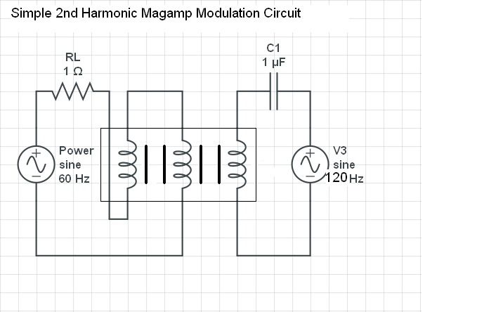
                        As suggested by Eric Dollard, how do we construct a magnetic amplifier circuit to use as a means of synchronous parameter variation at the 2nd harmonic of the power wave? If you just simply connect up a circuit like this, complications will occur.


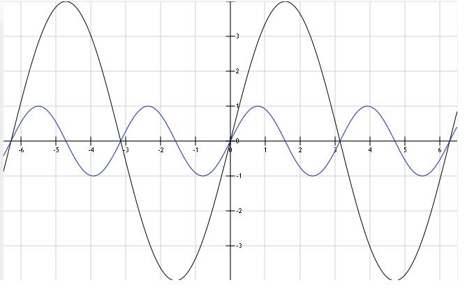
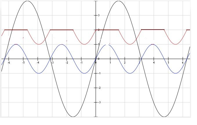
                        The above circuit will have the following waveshapes where the function shown in black is the power wave (carrier wave) and shown in blue is the modulation wave:


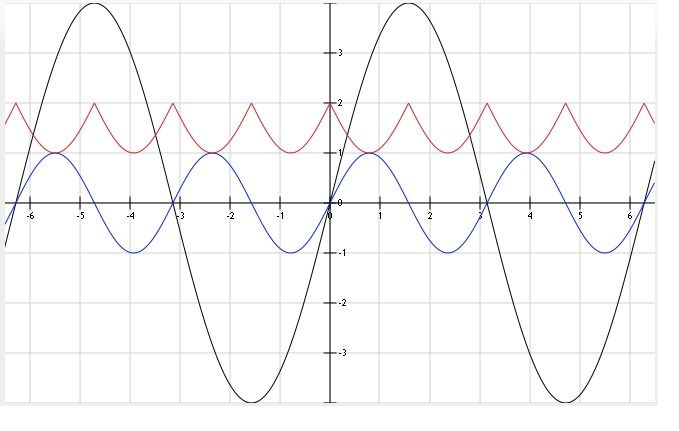
                        The above graph seems like it is suited to be the correct waveshape that we want for our modulation, HOWEVER, if you start taking DC inductance measurements for both polarities of ampere-turns in the control winding, you will see that the inductance of the power windings decreases with each half cycle of the modulation wave, giving 4 minimum inductance peaks rather than 2 as shown by Steinmetz's diagram above. A graphical representation can be seen below, inductance colored red:


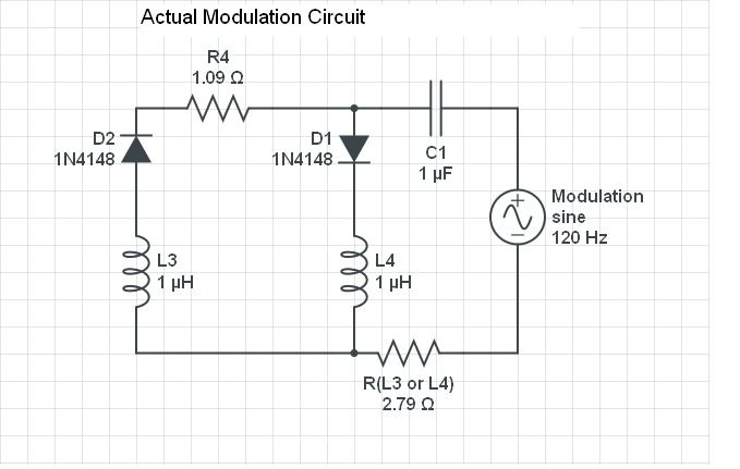
                        As can be seen by the series capacitor in the "Simple Second Harmonic Magamp Modulation Circuit", the modulation portion needs to be in resonance to effectively deliver enough current into the impedance (control winding) that will in turn deliver the ampere-turns of magnetism into the core. After many, many hours of trying every damn thing that I could to overcome this problem of the 4x inductance crests/troughs, I found a simple solution. Two identical control windings and a couple of diodes! So easy...

                        *R4 is the 1 ohm resistor for current detection.

                        This arrangement allows for unidirectional current only in the control winding of the magamp under study. It still doesn't have the sinusoidal shape that Steinmetz's has, but the inductance variation becomes isolated to only two out of the four quadrants of rotation. It has produced the best looking waveforms that I have seen on my scope to date.


                        This configuration would be best used on a four phase electrical system. Then all diverted control winding current could be utilized to modulate another core, creating a balanced system.

                        This sums up how I have been running my modulation experiments, and I'll be posting some data to accompany this when I can stand to sit down at the computer again.

                        Until then...

                        Dave

                        Comment


                        • #42
                          http://www.energeticforum.com/renewa...m-papalex.html This link is the second post in the parameter variation machine thread. It is not as important as the others but just shows some other figures in the circuit before I disassembled/reassembled the core.
                          Last edited by Web000x; 07-22-2012, 04:15 AM.

                          Comment


                          • #43
                            Interesting Results

                            ***POST DELETED***

                            @All,

                            Sorry but it turns out that I had a connection issue going on that interlinked the two control windings. This interfered with the measurements which makes these results null and void.

                            I didn't mean to get anybody excited...

                            Dave
                            Last edited by Web000x; 08-02-2012, 03:06 PM. Reason: Data was not correct

                            Comment


                            • #44
                              Hello,

                              How would you go about applying this modulation to a motor or generator which is capable of producing the blue waveform...?

                              Regards

                              Comment


                              • #45
                                The blue waveform (voltage across 1 ohm resistor) would be a sinusoidal waveform IF the inductance had remained unvaried throughout the AC cycle. Anything capable of producing an AC wave can be modulated to create this waveform. The only requirements are that the inductance must be high during the charging of the inductor, low during the discharging of the inductor, and the magnification factor must be fairly high or there will be no negative power factor. See "Reaction Machines" in "Theory and Calculation of Alternating Current Phenomena" for more detail.

                                Dave
                                Last edited by Web000x; 07-22-2012, 08:28 PM.

                                Comment

                                Working...
                                X