Announcement

Collapse
No announcement yet.

Eric Dollard

Collapse
This is a sticky topic.
X
X
 
  • Filter
  • Time
  • Show
Clear All
new posts

  • Thanks

    Originally posted by dR-Green View Post
    I'm using this

    MWG05 1Hz - 5MHz DDS Signal Generator Source Module TTL Output with Sweep Scan | eBay

    But as a warning I'd say you get what you pay for. I can do a frequency sweep and get all the measurements, then go back to the start and the noted measurements are 2mV out. So that wastes some time, what seems to make it a bit better is to turn it on an hour before I want to use it and do some frequency changes. It acts differently above and below the resonant frequency of the coil so apparently doing this before taking measurements makes it a bit more reliable. But it's ok considering the price of the nicer signal generators, the USB interface is a nice feature.

    For measurement, the scope is a Pico ADC-200, being PC based it has meters and XY scope and spectrum analyser etc so it can almost do everything that's required here in itself. But digital being what it is, it's "acceptable".

    On the analogue side, AVO 100μA ammeter which is now a part of the ARRL RF current probe and was originally used as the "Field Intensity Meter" Eric posted. TMK Model 500 works ok to measure the potential on the 2.5V AC range, but the AVO Model 8 Mk2 does not. 1.5v 15mA bulbs are currently in transport via the Chinese connection (ebay).

    Amplifier is a DIY 2N2222 with 50 ohm output impedance which I just got up and running a few days ago but needs some tweaking for more voltage gain. At the moment I only have 2v RMS going to the single turn test coil, but it's finally an amp that works I'm starting to be able to light neons and fluorescent tubes with the coil when it's unearthed.
    dR G, thanks for the info given on the equipment you use. I've ordered myself the MWG05 signal generator as mentioned. An amplifier to bulid next. I have partially built the 2050 thyratron circuit. I have the cathode supply, and laboratory grade variable DC power supply (50v-3Kv @ 3mA) for the Anode supply. So now I am considering what square-wave signal is needed to supply the grid etc. So I'm reading up on this. It would be nice to interface the MWG05 signal generator to the 2050 Thyratron(s) (Although I know T-rex wouldn't approve of a digital device fed thyratron). So in my case I would then have a 650v @ 3mA which is only about 2 Watts. While low power this should be enough to take measurements etc. I've partially constructed & collecting the analoge 'test equipment' also.

    Soon dR G, you'll have the neighbours complaining of strange 'Rolling Thunder' sounds coming out of their toaster! Hehe.

    You guys should listen to the Laura Lee interviews with Gerry Vassilatos, it is very interesting, great stuff. Gerry is well spoken & wonderful infomation given. "VRIL - Old French for a Certain type of pattern found in nature; Activity of divine being in the Earth". Gerry Vassilatos mentions the name 'Eric Dollard' SEVERAL times.
    "Doesn't matter how many times you kick the coyote in the head, it's still gonna eat chickens". - EPD

    Comment


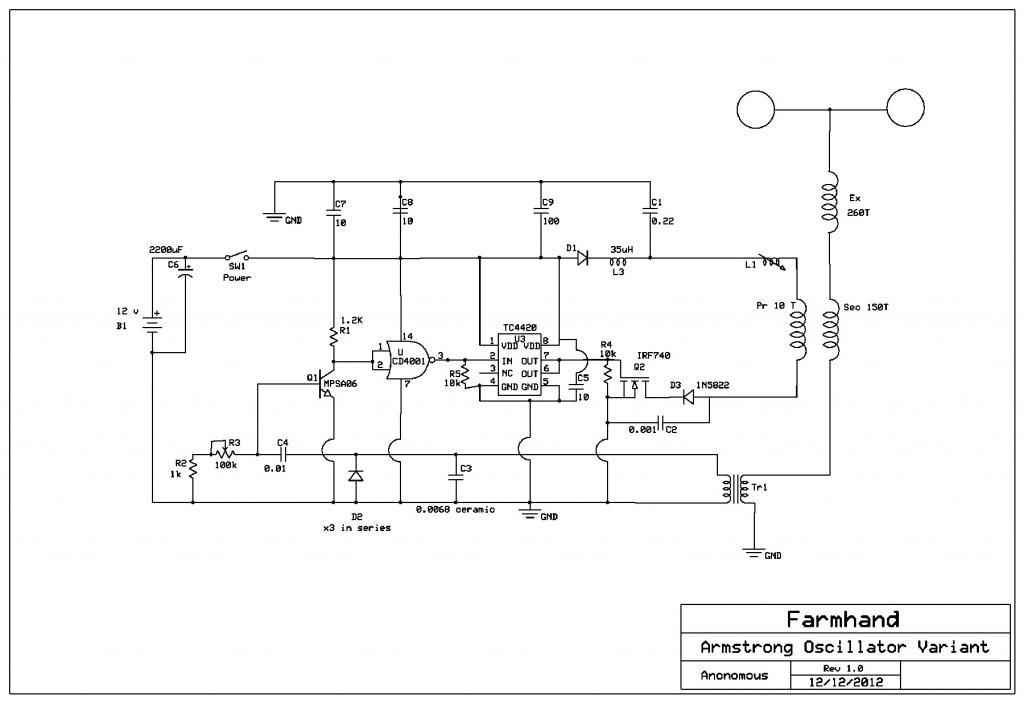
    • Hi Guys I thought you fellows might be interested in this circuit I developed
      for experimenting, it's an Armstrong oscillator variant to use with a mosfet.
      They also work with tubes and I think that is the original purpose of the basic circuit.

      The main point of this post is the circuit for driving the transformers not the
      transformers themselves. Any adverse comments about the transformers
      themselves will be ignored. They are a tool for testing the circuit and serve
      their purpose quite well.

      The secondary resonant frequency is automatically found. As the circuit is
      approached it keeps the input in step with the effective working frequency.
      The secondary ground can be a separate RF ground. the inverting buffer can
      be omitted if an inverting mosfet driver is used. The mosfet driver I used gets
      a bit warm at frequencies over 1000 kc.


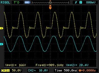
      Here is a shot of the secondary waveform from a remote probe (blue trace)
      and the yellow trace is the primary negative coil end to circuit ground.
      input is 12 volts for 160 volts or more across the primary, input is about 3.5 Watts
      max and can go down to very little. It looks to me like the mosfet conducts at
      Zero volts on the up and turns off at zero current near the top.


      In this video I use the circuit to produce Meyl Style effects. But it can be
      used for testing a single coil or twin coils in opposition.

      I used the tuning coil to wrap the tickler coil on and so I can't use that for
      tuning the secondary frequency any more.

      Two Receivers and Armstrong Oscillator Transmitter - YouTube

      Cheers
      Last edited by Farmhand; 12-14-2012, 02:53 AM.

      Comment


      • Vacuum Tubes, Tesla, Pierce Arrow & Moray

        Vacuum Tubes:
        Much has been written about Nikola Tesla and his Pierce Arrow electric motor car and in particular the 12 Tubes that he was supposed to have used.
        It was suggested that 70L7GTs (Rectifier- Beam Power Output Tetrode) were the ones but this, with a little research proved impossible as they were not in manufacture in 1931 and actually began in 1947, some 16 years later after WWII.

        As a consequence and over a long period of time and further research I have been looking at what those Tubes could really have been.
        At this particular time, an exciting one for the Industry in the early 30s, Cunningham Tubes were taken over by RCA and De Forrest and Kenrad by GE.
        This was also the time that Tube numbering changed from a 3 digit code down to a two such that a 201A became a 01A.

        You may recall me saying that I had Tubes coming from the US and to the best of my calculations, they are the same Tubes that Tesla was using in the Pierce Arrow as they began manufacture of these in 1929 and were most popular.

        They are 24As (C-324-A, 224, 224A, 124, UY-24B, NY224, UY224A, 424A, FY224, T24, PH224A, MY224)!

        A Screen Grid Tetrode that could be used as a detector, oscillator or amplifier and also had very strong, stronger than any other, 'negative resistance' characteristic and was sold as suitable for both IF & RF uses.
        Sticking my neck out here but there are many reasons why Tesla would choose such a Tube compared to others available.
        The other option that I made was for a 201A but their time was earlier from 1925 and were a straight Triode.
        I believe Tesla would have preferred the later Tetrode.

        Here is the E T Cunningham Manual that dates 1932 and see the C-324-A on page 35:

        http://www.introni.it/pdf/Cunningham...s%20manual.pdf

        Cunningham added a 'C' and a '3' to all of their products.
        Take particular note of the 'Average Plate Characteristics' on page 36 where you see a negative voltage below the baseline and the reason why it was so popular.

        This same feature was progressively removed from Vacuum Tubes over a period of time with the introduction of the Pentode in a further SCREEN grid to prevent this phenomena from occurring.

        I am hereby tying in together, both the LMD wave and 'negative resistance' as I believe it is the same phenomena but originating from differing organisations and being displayed in differing mediums, one air, one plasma but both essential qualities for 'Energy Synthesis'.

        I now notice in the Moray schematic in the top diagram he shows the use of two of his 'Valves' but only one in the lower.
        I am still very confident that both Tesla and Moray were assisting one another as their Radio feats are following similar paths when you begin to uncover the real story.
        Moray was using 112, 201A and 210 Tubes in 1927.

        Don't expect my parcels (two different sources) to arrive until after Christmas as the postal industry is in overdrive at this time of year.
        (Breaking News - first set of 3 arrived today, NOS - 9 days, not bad!).

        If anyone here would like further information where to buy these Tubes for experiment, please contact me off line as I have cleaned out the cheapest source in the US but he may have more available if there is a demand and what I have coming are all tested OK and this guy goes out of his way to assist. ($US 3.95).
        More on this later as the available hints were simply too many to ignore and the many shoulder 'taps' I was also getting.
        I have always had a particular attraction to the Anode in the rounded form using a mesh type double screen and this is also what is inside Moray's condenser Tube with the quartz granules as the dielectric.
        The surface area here is HUGE which is the basic attraction.

        Not too many have travelled along this route as their knowledge of Vacuum Tubes was severely limited as I pointed out above but is now becoming clear as facts and reality come together.
        Thanks.

        Smokey

        Comment


        • It's all about negative resistance, the tubes were replaced by tunnel diodes and solidstate circuits, however the tunnel diode does not perform the same as a tube.

          Smokey, have you checked out this mfg? Arcturus

          an updated 24A, Screen grid tetrode. Originally issued as the 551 by Arcturus, this was the first variable mu tube. This tubes characteristics were very similar to the type 35, and eventually the two types were merged as type 35/51. Several companies, among them Raytheon and Sylvania made both a 551 and a 235.

          need to track down the curves to see the negative slope.

          Comment


          • Characteristic Curves

            Smokey,

            Thanks for the info on the alternative electrode configuration (for a tube based electrometer) and the book references. I've downloaded quite a few other books from that website (tubebooks.org) as well, definitely a great resource for information on tubes and early transistors.

            -------------------------------------------------------------------------

            Since the topic of "negative resistance" is being brought up, I thought I would share a few thoughts I have on the subject.

            Oddly enough, my current "research project" involves the study of amplifiers and the associated characteristic curve of various electrical networks used in them. A network could be a tube, a transistor or anything with two or more terminals. In this direction, a DC I-V plot is usually drawn, this being performed as a "voltage sweep" of the network. Used to find the incremental increase or decrease of current per applied voltage. (AC I-V, phase and frequency response can be done as well)

            Generally, most all OHMIC networks are linear and the applied voltage and subsequent current form a straight diagonal line (having a positive slope), this relates to a constant resistance. With tubes, transistors, magnetic & dielectric amplifiers, this is NOT the case. The characteristic curve is NOT linear throughout the whole range of applied voltage. The plot will generally have an "ohmic" region (different for magnetic & dielectric amplifiers though) that is somewhat linear (appears to be a diagonal line). The plot then abruptly, or gradually, (depending upon gain - higher gain is a more steep plot) go in to what is called the saturation region. This is where the slope of the plot becomes nearly 0 and thus useless for an amplifier (the diagonal line curves to a horizontal line).

            An unusual effect can some times manifest IN BETWEEN the two conditions stated (ohmic region/saturation region), that is the characteristic curve can "bend" backwards and have a decreasing current for an increasing applied voltage. This is sometimes called a "pinching effect", and represents a NEGATIVE slope region of the characteristic curve.

            This negative slope region of the plot is used frequently in parallel LC oscillators, as the pinching effect creates and sustains the oscillatory motion. Whats interesting about operating in the negative slope region, under certain conditions, the effective resistance seen in the LC oscillator = 0. That is, the negative slope (of the "amplifier") is equal to the positive slope (sum of the paralleled resistance of the inductor and conductance of the capacitor) of the LC oscillator. Thus the oscillator has a high Q and is stable under external resistive loading.

            Is this effect real "negative resistance"? I'm not here to say it is or isn't, as this phenomena can be explained multiple ways. However, I currently hold the opinion that a negative slope device cancels a select portion of the effects seen by a paralleled or series positive slope device. In that the vector sum of their slopes negate one another for a select region of the superimposed characteristic curves. For the case |-s| = |+s| (with limits of operating only in that region of the plot), the effective loading resistance = 0, while an apparent limiting resistance is seen by the power source. Thus current is limited and resistance remains positive and NEVER goes into a NET negative value. Quite confusing, from first glance, at least for me. This is probably why engineers prefer to say "apparent differential negative resistance" over "negative resistance".

            In summary, I think its best to say that the resistance is always a net positive value (at ANY point on the plot), but the operating slope is whats negative. Subsequently, it's the vector sum of discrete slopes (from two or more networks) that creates the observed phenomena not negative resistance. The entire problem can be reduced to trigonometric and graphical analysis for an incredibly convenient and lucid solution - resembling AC graphical methods and even has the possibility to involve Mr. Dollard's versor operators, which is what I am currently working on doing. As a final concluding point, parametric variation of resistance r, can synthesize an "apparent differential negative resistance".

            The main theme to take away from all of this, is the interesting effects observed by operating in the NEGATIVE SLOPE region (of the characteristic curve) for an arbitrary network. The "lambda diode" is a fun way to start out in understanding whats going on, as it has very pronounced effects[1] and is easily obtained by joining two j-fets (P-type and N-type). More advanced networks include select vacuum tubes, BJT transistors and saturated magnetic or dielectric amplifiers, all of which exhibit the effects more or less in some form.

            [1] The lambda diode I assembled went from 91-ohms at 0.5V to an astounding 1-gigaohms at 14v. The linear portion of the negative slope region began at 7V and ended at 10V - this being the useful region of operation. This section approximately equated to -180-ohms of resistance, *however*, it is always a net POSITIVE value, like AC superimposed on DC, it never goes truly negative. The positive slope is observed from 0V to 6.99V. An interesting event which I have dubbed the "flat line" occurs at proximately 11V, where effectively no current will pass through the two-terminal network, series resistance ramps up to billions of ohms. The "flat line" region, from what I have read is supposed to act like a surprisingly large capacitance, I haven't tested this yet as I need to build a DC bias jig for my LCR meter, but I should have some data collected on this soon after completing the bias jig.

            *I will admit, contrary to my above statements, that if we are dealing with real negative resistance, we CAN NOT use "resistance" r in the normal sense. It now becomes ΔV/ΔI = (V_2 - V_1) / (I_2 - I_1) = r. r is negative for the limiting case I_2 < I_1. Yielding a sudo voltage source equal to I*-r=V, instead of a DROP I*r=-V (where (positive) r = (ΔV/ΔI) for the limiting case I_2 > I_1). These expressions state that the two-terminal network will only be a voltage source due to an EXTERNAL current. In this sense, the apparent resistance seen by the source and zero effective loading resistance seen by the LC tank is more palatable. That said, I haven't worked this theory out that far, so it may be flawed in some major way, the best bet is to the ONLY use the transfer characteristics of the slope for analysis and not assume any real negative resistance. However, if you take the vector sum of the two slopes, -s_0 & +s_1, as the limiting resistance (which is dynamic, if s_e=0 then its a constant current circuit) and the vector sum of the apparent voltage source, I*-r=V_as, and voltage drop, I*r=-V_d, as equaling zero then this might actually make sense. You also need to account for the LC tank as a voltage source as well... I need to do some more thinking on this before elaborating any further.

            Garrett M
            Last edited by garrettm4; 12-16-2012, 11:33 PM.

            Comment


            • Originally posted by garrettm4 View Post
              Smokey,

              Thanks for the info on the alternative electrode configuration (for a tube based electrometer) and the book references. I've downloaded quite a few other books from that website (tubebooks.org) as well, definitely a great resource for information on tubes and early transistors.

              -------------------------------------------------------------------------

              Since the topic of "negative resistance" is being brought up, I thought I would share a few thoughts I have on the subject.

              Oddly enough, my current "research project" involves the study of amplifiers and the associated characteristic curve of various electrical networks used in them. A network could be a tube, a transistor or anything with two or more terminals. In this direction, a DC I-V plot is usually drawn, this being performed as a "voltage sweep" of the network. Used to find the incremental increase or decrease of current per applied voltage. (AC I-V, phase and frequency response can be done as well)

              Generally, most all OHMIC networks are linear and the applied voltage and subsequent current form a straight diagonal line (having a positive slope), this relates to a constant resistance. With tubes, transistors, magnetic & dielectric amplifiers, this is NOT the case. The characteristic curve is NOT linear throughout the whole range of applied voltage. The plot will generally have an "ohmic" region (different for magnetic & dielectric amplifiers though) that is somewhat linear (appears to be a diagonal line). The plot then abruptly, or gradually, (depending upon gain - higher gain is a more steep plot) go in to what is called the saturation region. This is where the slope of the plot becomes nearly 0 and thus useless for an amplifier (the diagonal line curves to a horizontal line).

              An unusual effect can some times manifest IN BETWEEN the two conditions stated (ohmic region/saturation region), that is the characteristic curve can "bend" backwards and have a decreasing current for an increasing applied voltage. This is sometimes called a "pinching effect", and represents a NEGATIVE slope region of the characteristic curve.

              This negative slope region of the plot is used frequently in parallel LC oscillators, as the pinching effect creates and sustains the oscillatory motion, similar to but no the same as the positive slope region. Whats interesting about operating in the negative slope region, under certain conditions, the effective resistance seen in the LC oscillator = 0. That is, the negative slope (of the "amplifier") is equal to the positive slope (sum of the paralleled resistance of the inductor and conductance of the capacitor) of the LC oscillator. Thus the oscillator has a high Q and is stable under external resistive loading.

              Is this effect real "negative resistance"? I'm not here to say it is or isn't, as this phenomena can be explained multiple ways. However, I currently hold the opinion that a negative slope device cancels a select portion of the effects seen by a paralleled or series positive slope device. In that the vector sum of their slopes negate one another for a select region of the superimposed characteristic curves. For the case |-s| = |+s| (with limits of operating only in that region of the plot), the effective loading resistance = 0, while an apparent limiting resistance is seen by the power source. Thus current is limited and resistance remains positive and NEVER goes into a NET negative value. Quite confusing, from first glance, at least for me. This is probably why engineers prefer to say "apparent differential negative resistance" over "negative resistance".

              In summary, I think its best to say that the resistance is always a net positive value, but the operating slope is whats negative. Subsequently, it's the vector sum of discrete slopes (from two or more networks) that creates the observed phenomena not negative resistance.

              The main theme to take away from all of this, is the interesting effects observed by operating in the NEGATIVE SLOPE region (of the characteristic curve) for an arbitrary network. The "lambda diode" is a fun way to start out in understanding whats going on, as it has very pronounced effects and is easily obtained by joining two j-fets (P-type and N-type). More advanced networks include select vacuum tubes, BJT transistors and saturated magnetic or dielectric amplifiers, all of which exhibit the effects more or less in some form.

              *I will admit, contrary to my above statements, that if we are dealing with real negative resistance, we CAN NOT use "resistance" r in the normal sense. It now becomes a sudo voltage source equal to I*-r=V, instead of a DROP I*r=-V. These expressions state that the two-port network will only be a voltage source due to an EXTERNAL current. In this sense, the apparent resistance seen by the source and zero effective loading resistance seen by the LC tank is more palatable. That said, I haven't worked this theory out that far, so it may be flawed in some major way, the best bet is to the ONLY use the transfer characteristics of the slope for analysis and not assume any real negative resistance. However, if you take the vector sum of the two slopes, -s_0 & +s_1, as the limiting resistance (which is dynamic, if s_e=0 then its a constant current circuit) and the vector sum of the apparent voltage source, I*-r=V_as, and voltage drop, I*r=-V_d, as equaling zero then this might actually make sense. You also need to account for the LC tank as a voltage source as well... I need to do some more thinking on this before elaborating any further.

              Garrett M
              I'm sure you've read the technical info on negative resistance as it relates to the 2ndary emission of electrons in tubes. it's exploited for stable oscillation in UHF, hence the dynatron. granted it takes a voltage differential to start the effect, but it's not exactly the same effect in a tunnel diode. quantum tunneling is not understood on a fundamental basis in QED. this topic can get a bit out there. HUP is how it's explained, yet that isn't an answer really, this is also a result of C being the limit of the universe.

              I haven't taken the time to approach this effect from a pre-relativity view but it should be done. the other issue is the use of 'mechanical' wave optics to describe a higher order dimensional effect.

              This highlights exactly just how much work needs to be done from a mathematics standpoint to begin to understand these phenomenon without resorting to 'exceptions' and tunable variables.

              Comment


              • Vacuum Tube 24A

                Madhatter, GarrettM4,
                Thankyou for the responses.
                Didn't have the Arcturus data but most interesting and Fig 12 is the one we are after and shows the mesh Anode nicely.
                Had seen some reference to the 122 as also being a 124 and was confused by that reference but that article shows the connection.

                What I have also been doing in the background here is to find as much 'negative' as I possibly could and the next area of interest is naturally induction.
                Was concerned by always reading that 'negative resistance' was only 30 to 50% efficient but realise that that would be the case as both the Tube voltage and current would continue to increase overall as you advanced into the working slope area of the 'negative resistance'.

                Have always held the opinion that 'tunelling' as in Tunnel Diodes was a counterspace phenomena which we would have considerable difficulty in explaining and that applies to all of Solid-state.

                Will get the data together for the negative inductance and pass it on as this is all part of the Moray path.

                Looking at building Moray's Condenser tube which I believe to be what it was through the use of Granite/Quartz granules as the dielectric.
                Have an article here which shows the atomic nature of Granite and at one stage in the US (Arizona) it was going to be mined for its radioactive component being converted into energy but there is more to Quartz than this and need now to read Moray's work in this particular field.
                Will find the article and Post.

                Smokey

                Comment


                • Originally posted by David G Dawson View Post
                  Madhatter, GarrettM4,
                  Thankyou for the responses.
                  Didn't have the Arcturus data but most interesting and Fig 12 is the one we are after and shows the mesh Anode nicely.
                  Had seen some reference to the 122 as also being a 124 and was confused by that reference but that article shows the connection.

                  What I have also been doing in the background here is to find as much 'negative' as I possibly could and the next area of interest is naturally induction.
                  Was concerned by always reading that 'negative resistance' was only 30 to 50% efficient but realise that that would be the case as both the Tube voltage and current would continue to increase overall as you advanced into the working slope area of the 'negative resistance'.

                  Have always held the opinion that 'tunelling' as in Tunnel Diodes was a counterspace phenomena which we would have considerable difficulty in explaining and that applies to all of Solid-state.

                  Will get the data together for the negative inductance and pass it on as this is all part of the Moray path.

                  Looking at building Moray's Condenser tube which I believe to be what it was through the use of Granite/Quartz granules as the dielectric.
                  Have an article here which shows the atomic nature of Granite and at one stage in the US (Arizona) it was going to be mined for its radioactive component being converted into energy but there is more to Quartz than this and need now to read Moray's work in this particular field.
                  Will find the article and Post.

                  Smokey
                  It seems that with every passing yr there is more and more stuff posted to the web on tubes, nice to see it happen. Also amusing too is the retro-nature of it being re investigated in technology and scaled down.

                  Another bit of information, a smallish Co in San Francisco H&K made some interesting tubes where the cathode and anode where coated in tantalum, those engineers left H&K and formed Eimac in the mid 50's I think. the H&K tubes where called gamatrons, however not all actually where tantalum coated, the name was used across the line late in the Co's life.

                  here's a link to a tube site on the double digit codes: Two Digit Types From 1 to 100

                  those arcturus tubes are hard to come by esp the 551.
                  24's are still easily had and wont break the bank.

                  granite is indeed radioactive but not high enough to be a problem. not sure if granite would be useable as a dielectric in low pressure as it may out gas significantly due to the Fe and contaminate the anode.

                  Comment


                  • Mathematical Solution to Differential Negative Resistance

                    Alright, I sat down and got to work, and surprisingly, have formulated an outline theory of the "differential negative resistance" phenomena from an engineering point of view. I won't post all of it here as it would be a PIA to do so, but here's a few interesting points I developed.

                    --------------------------------------------------------------------------
                    The resistance calculated in an I-V plot is the reciprocal of the slope m at the section measured.

                    That is

                    m = ΔI/ΔE

                    Where,

                    ΔI/ΔE = (I_2 - I_1) / (E_2 -E_1)

                    Whereby I_2 & I_1 are two separate current magnitudes used as y-intercepts, that are paired with corresponding x-intercepts E_2 & E_1. That said, there are some limits and rules to follow, but that would get into a length discussion and will be omitted.

                    --------------------------------------------------------------------------
                    Since the slope directly relates to the effective current for an applied voltage, we can say that

                    m^-1 = r, effective resistance in ohms Ω

                    and conversely

                    m = g, effective conductance in siemens S

                    --------------------------------------------------------------------------
                    Developing this further,

                    When I_2 > I_1, then

                    90° > arctan(m) > 0°
                    or
                    m = a positive slope

                    That is resistance (m^-1) = a positive effective value in +Ω

                    --------------------------------------------------------------------------
                    When I_2 < I_1, then

                    -90° < arctan(m) < 0°
                    or
                    m = a negative slope

                    That is resistance (-m^-1) = a negative effective value in -Ω

                    --------------------------------------------------------------------------
                    For the special case, I_2 = I_1

                    arctan(m) = 0°
                    or
                    m = no or zero slope

                    which reduces slope to m = I/ΔE, a constant current condition

                    In this state, the resistance, or conductance, is LINEAR and is defined by the constant current,

                    Whereby, a slope of m_I=0 for current equates to a slope m_r=1 for resistance

                    That is, when arctan(m_I) = 0°, arctan(m_r) = 45°

                    Resistance is positive and linear in this constant current condition.

                    --------------------------------------------------------------------------
                    I'll end here as this has gotten quite long, but as can be seen trigonometric analysis and ohms law can easily describe whats going on with a simplicity that I find refreshing.

                    Garrett M
                    Last edited by garrettm4; 12-15-2012, 08:05 AM.

                    Comment


                    • Originally posted by David G Dawson View Post
                      ... and need now to read Moray's work in this particular field.
                      Smokey
                      Moray's energy emanated from inducing elemental decay - fractional controlled devolution of matter - scaringly called radioactivity - the Endless Light from within our Sea of Energy. As did Lester Hendershot, but never openly stated by Tesla, though could well have empowered his Pierce Arrow, as did Hubbard his boat.

                      This energy does not come from coils or antennas, or free space or so called Zer Point, but from the Stardusts of life itself.

                      Cheers ...... Graham.

                      PS. In the circuit below, not all components can be said to be exactly as they would appear to an unknowing eye.
                      For example a capacitor might contain anything. A functioning tunable inductor could be fashioned from a low ohm rheostat. The stroking of an overwound steel horseshoe magnet is akin to initiating a pulse-train oscillator. Radioactive doping of crystals could form quenchable oscillators. Dissimilar metals would constitute a contact rectifier for ion as well as electron charge flow. An antenna could be a hi-Z counterpoise. Ionic conduction through air would be much slower (phased) than any related electromagnetic reactivity. Lamp output is likely RF too, or heterodyned, with much invisible circuit layout feedback totally unimaginable to the unexperienced, or anyone unfamiliiar with a specific construction.
                      Attached Files
                      Last edited by GSM; 12-15-2012, 11:02 AM.

                      Comment


                      • Regenerative Receiver &amp; Amplifier

                        After reading all of Ramon Vargas' papers (on radio related topics) over at "Circuit Exchange International", I think finally I understand what Dr. Tesla and Mr. Dollard are saying.

                        Tesla says that the "energy" sent to the transmitting apparatus (i.e. "Tesla Coil") IS NOT spent (or exhausted) as RADIATION strewn into free-space. When examining the primary of the apparatus, we find an LC resonant tank. It is this very LC tank that STORES all the sent transmitting energy that ISN'T actually transmitted though the longitudinal link between transmitter and receiver. When employing a differential negative resistance, i.e. spark gap or other ΔV/ΔI two-terminal series network exerting -r, we have a REGENERATIVE AMPLIFIER, whereby effective resistance at the LC tank = 0. Thus we have a "magnifying transmitter", NO FREE ENERGY HERE, just plain simple circuit theory.

                        On the receiving end we employ the same apparatus but in a counter-wound form. Here the LC tank becomes a piece of a REGENERATIVE RECEIVER, whereby another ΔV/ΔI two-terminal series network exhibiting -r is used to eliminate dampening and thus amplify the signal via regenerative means. That is, the LC tank continuously stores energy (given to it by the secondary) until a limiting condition is observed. This process can passively amplify even the smallest of signals to incredible levels.

                        It can now be seen that the primary circuit, of any Tesla coil, becomes a load and source for the apparatus. This is why the LC tank LOWERS the resonant condition of the Secondary and Extra. That is, the primary places a resistive burden on the one-wire transmission line due to the storage of energy in the resonant tank.

                        A further examination of the Extra-Secondary interaction is found to be in the form of a "mechanical pump" - an analogy Tesla himself used frequently. The difference in impedance of the two one-wire transmission lines causes a reflected wave to be passed into the earth causing an increase in "earth current". Whereby the greater the earth current, the more "pressure" that can be exerted on a receiving unit. However, the greater earth current causes a simultaneous increase in terminal voltage, which Tesla himself has shown to be quite problematic.

                        Reducing the system into discrete elements:

                        Primary system:
                        -rLC regenerative Amplifier/Receiver

                        Primary coupling with Secondary:
                        T.E.M to L.M.D Transformation

                        Extra to Secondary:
                        "Reflection" Amplifier (This is why the Extra coil ISN'T ALWAYS USED. It serves as part of a special type of amplifier)

                        Secondary to Earth:
                        "Current Pump" for Longitudinal Coupling

                        Concluding, the reflection coefficient between Secondary and Extra determines the characteristics of the reflection amplifier. The "quadra-polar" oscillation of the secondary, by Primary coupling of *Transmitter*, is the conversion mechanism for the T.E.M to L.M.D. transformation. Whereby Kirchhoff's circuital laws are no longer obeyed and the DIELECTRIC and MAGNETIC energy oscillating in the coil is of equal magnitude for a balanced condition as seen in a transmission line. Thus the secondary reduces to a one-wire transmission line that is loosely coupled with the primary and reflectively coupled with the Extra. Forming a T.E.M. to L.M.D. "current pump" that uses the Earth earth as an analogue of an inflatable balloon. A receiver recovers the pressure wave sent though the Earth "balloon" as an oscillation of the Secondary in the *Receiver* circuit. The Extra coil of the Reciever serves again as a form of reflection amplifier and the -rLC tank of the primary de-couples energy from the Secondary into a regenerative resonant amplifier. Finally, a demodulator can be connected to the Receiver Primary and the intelligence imparted to the signal can finally be heard. All of this being done telluricly through the earth and NOT though free-space as a Hertzian wave would be.

                        That's my best effort at describing the system using NORMAL explanations, no free-energy no exotic physics shenanigans. Just all very common radio techniques; transmission line theory, -r regenerative circuits and reflection amplifiers. However, the T.E.M. to L.M.D. section is off limits to convention, but it has been proven to be real so I don't think this serves as an "exotic" abstraction.

                        *Final note, Mr. Dollard makes reference to the Primary being either a constant current or a constant potential circuit. This is due to the usage of either a ΔV/ΔI = -r or ΔI/ΔV = -g. That is, when the positive slope dissipative parameter is equal to a negative slope dissipative parameter resistance (series elements) and conductance (parallel elements) are no longer of constant values but become a dynamic linear value to the source supply. This forms either a constant current circuit (when |-r| = |+r|) or a constant potential circuit (|-g| = |+g|). Hence why Mr. Dollard makes reference to both in connection to spark gaps and the Farnsworth multipactor tube, as they exhibit negative current or voltage slopes.

                        Some thoughts,
                        Garrett M
                        Last edited by garrettm4; 12-17-2012, 04:03 AM.

                        Comment


                        • Adding a primary condenser complicates things for sure. Is it supposed to be impossible to get a higher potential with a condenser than without? I think the output capacitor of the transistor amplifier is not a good thing here too.

                          Primary condenser aside, initial tests with an AV plug and crystal earpiece indicate that even when not set up properly and not tuned to any particular frequency in any way, either the extra coil and/or the higher potential with the extra coil yields better "Telluric transmission". Coils tested were the new secondary, new secondary with extra coil, and 52cm diameter flat spiral coil. The bigger coil was to test a lower frequency. The most effective with AV plug "receiver" was with the extra coil and higher potential. Now it remains to increase the amplifier gain to get a higher potential with the other coils, approx equal to what was obtained with the extra coil to determine whether it's just the potential.
                          http://www.teslascientific.com/

                          "Knowledge is cosmic. It does not evolve or unfold in man. Man unfolds to an awareness of it. He gradually discovers it." - Walter Russell

                          "Once men died for Truth, but now Truth dies at the hands of men." - Manly P. Hall

                          Comment


                          • dR-Green,

                            The condensers resonance with the primary definitely burdens the secondary/extra setup so I would assume you're right. For receiving applications it most probably lowers the secondary/extra field strengths, but in a transmitter it "should" increase them to some degree. In "theory", the LC tank can be used magnify the signal at the receiver end, despite all the burden it puts on the secondary/extra. The main problem lies with dampening of the LC tank, if dampening is high, then no magnification in the LC tank can take place. If really high no oscillation will ever take place, over damped.

                            For a more "Victorian" esque setup, you could replace the spark gap with a lambda diode in series with the LC tank consisting of the Primary loop and variable capacitor. Then connect the "drain" terminal of the lambda diode to a variable resistance for tuning and then to the positive connection of a variable DC supply. The ground connection of the LC tank connects to the negative of the power supply. The variable DC resistance will help tune the lambda diode and the capacitor sets the operating frequency. The DC supply voltage will need to be determined by plotting the I-V characteristics of the lambda diode you will have to make. Similar to whats shown here.

                            An even more "crystal" esque setup, would replace the lambda diode with an oxidized zinc "base" and a "cats whisker" (fine stiff wire), used to find a good point on the base that has a negative slope region. This will cause oscillations but is really only good for "show and tell". This is shown here.

                            Both of these circuits form a regenerative amplifier or receiver depending on how they are used. And neither require an external oscillator just a low voltage DC supply. Not saying this is the best way to go, but its worth testing to see the effect. The guy over at SparkBangBuzz seems to really like negative resistance oscillators in his transmitters, so this does seem more on the practical side of things.

                            For the AV-plug, I'm rather unsure as to why its working at all. It obviously gets results, from what you have said, but the operating principle is beyond me. There are most definitely different types of longitudinal coupling just as there are for transverse wave antenna. That said, I'm not entirely sure that it is a detector for L.M. earth currents, could be operating as an L.D. displacement current detector (or another form of detector)? Who knows.

                            Regards,
                            Garrett M
                            Last edited by garrettm4; 12-22-2012, 06:13 AM.

                            Comment


                            • LMD 24A Mesh Screen

                              LMD 'wave' - what is it?
                              Been messing with the CSI with the intent of gaining some knowledge about this LMD 'wave'.
                              As I could already clearly hear the AM station signal through the headphones, I set up the 11awg 55 turn Extra coil about a meter away thinking that if I were trasmitting/radiating something it should be able to be received by that coil or any large coil for that matter.
                              Sure enough quite easily so in the second set of headphones at about level 5 where I would rate the original pickup point at 8 and note the distance is now 40"/1 meter away and not the 20" of before.
                              However, with the original pickup point in between I decided to move it out of the way and in so doing, lost the signal at the second Extra.
                              Conclusion being that this point is reradiating or redirecting or reflecting the signal.
                              Both coils are connected to the same ground mesh.

                              I moved the Extra further away again to about 2 meters and connected to the same ground plane and signal is still there but at slightly reduced level.

                              What concerns me most is that I can go out to my fenceline and hear by contact the local AM Radio station on any of the fence strands, once again NO direct 1/4 wave calculated antenna wire here, just a long piece of wire like in any strung antenna.

                              What was also evident with the 6' gap was another signal in the background which I would assume to be the other station, the ABC with a 'T' antenna, Commercial is a Dipole - both are about 7 Kms distance at 2Kw each.
                              Dipole for local saturation for the Commercial and 'T' for local plus regional distribution for the National.
                              However, what I had to do to receive this signal is use the finger capacitance at just a certain pressure touch to hear into the background.
                              Will try now to discriminate the signals.
                              Body capacitance is huge with this wave as I would expect that body capacitance is changing the E & B field angle.
                              Moving first antenna now has no affect on signal which is puzzling.

                              In the LMD wave, both the E & B field are in unisom and not 90º diverged as in the TEM wave.
                              I would like to be able to see this angle such that it could be used as a means for tuning and that may be possible with two probes, one in contact and one not and this should be able to be represented in an analogue meter but may need some good op-amps and then again Mr Dollard may not approve of that.
                              More on this as I gain experience before power up.

                              All 3 x 24As were NOS (new off shelf), 94, 96 & 99% - not bad for some 50 years plus!

                              Vacuum Tube history:

                              Principles of radio communication : Morecroft, John H. (John Harold), 1881-1934 : Free Download & Streaming : Internet Archive

                              (!) Poulson Arc
                              (2) Alexanderson Alternator
                              (3) Goldschmidt Alternator
                              (4) Iron In saturated Cores
                              (5) Marconi Series Of Spark gaps
                              (6) Oscillating Tubes

                              This information came from an advertisement here on page 63:

                              http://www.vacuumtubeera.net/RadioBr...15-1929-10.pdf

                              Information on 24As (Cunningham C-324-A) on 'Grid-Leak vs Bias detection' and I see a comparison plot there between 324s and 327s for selectivity and sensitivity and we can see which is best for both.

                              Quote:
                              "It is evident that both the sensitivity and selectivity is decidedly superior with the C-324 tube".

                              This may be a quality of the large mass of the Anode mesh and the inner mesh as well as the 'negative resistance' component.

                              Feel that both of these Tube qualities would be exactly the ones that Tesla would be searching for.

                              There is a phenomena associated with the mesh structure over a flat metal plate and have been collecting this type of Tube in preference to other organisations and am working on a theory.

                              Much like a kind of reaction taking place within the mesh squares itself which is unable to occur in a flat plate and this may lead to increased surface area and other phenomena which I could associate with 'oscillatory chamber' type architecture.
                              Also the reason why Moray was using a mesh for his grids.

                              Should also mention that Tesla was a stickler for anything associated with 3, 6 & 9 and 24A = 2+4 = 6 and Cunningham 324 = 3+2+4 = 9, funny that, don't you think?

                              Article on the smaller Alexanderson Alternator is the first I have seen and is excellent material.
                              John, David, can you get that one off to Eric please as we haven't seen much of this side of Alexanderson.
                              Thanks.

                              Smokey

                              Comment


                              • Originally posted by garrettm4 View Post

                                *The field of parameter variation is quite vast; ohmic, dielectric and magnetic elements all serve as starting points, however reactive elements hold the most potential. For the reactive components, amplifiers can be built using as little a 3 terminals, much like a tube or transistor. The variation of say permeability or permittivity can take a DC current and change it into an AC current. Alternatively you can pass AC though the element and modulate it with a second signal. You can form special LC oscillators powered only by the parameter change. For over-unity seekers, you can uses step changes in the parameter along charge and discharge quadrants of a carrier wave to cause excess reactive energy return or alternatively a new form of reactive loss. Formulation of negative slope characteristic curves yields effects of negative circuit elements -L or -C. Many more uses and configurations are possible, it just comes down to realizing that they exist and subsequently where and why to use them.

                                Regards,
                                Garrett M
                                Hey Garrett,

                                I know that in a post a while back that you had mentioned that you feel you have been quite successful with parameter variation for energy synthesis. What did your control winding power consumption do when you loaded the power windings? Everytime that I load my power windings, the control winding power consumption would go up accordingly. It would seem as if there is a transfer of power thru an admittance since the magnetically opposing power windings offer an EMF cancellation. In the limited geometries that I have experimented with, it seems that every geometry shows the same proportional increase of control winding energy consumption to the load dissipation of energy at the output. I noticed that you had a setup where you are using microchip controlling to get better control of timing on your setup. Are you using square waves or sine waves? I can't help but think that natures tenancy to operate using sine waves would be the more natural expression of any energy synthesis phenomena. Any hints welcome...

                                Dave

                                Comment

                                Working...
                                X