I won't get angry but I will point out as I said Eric has reviewed all this data. Also I have more than one coil. Everything is optimised on the final two so it's not because the wire is too thin. All the coils act alike regardless of that.
To make sense of the whole thing it needs to be in the context of other relevant data, for example frequency in relation to the conductor length. This indicates the mode of resonance and propagation velocity etc. A frequency floating in mid-air is just a number and it doesn't mean anything by itself, which is why I asked for all the data.
Also I don't use a primary condenser for these tests because my intention in this case is to get data on the secondary, and a primary condenser, like all other things, will affect the results.
Anyway I was observing the phase along the coil last night before the laptop broke so I'll have more to say about that at a later time.
-
I see a number of frequency specs but because you had a weired story about harmonics I doubted that those where normal frequency sweeps. If they are however than I see your coil acts transversal just like your measurements of I and E indicate. What might be interesting to investigate is if perhaps your mutual capacity and mutual inductance vallues are to low. That might be because the wires are to small and to far away.Originally posted by dR-Green View Post
If I look at my frequency plot and you have to believe me for now I see the peaks rising from left to right. There was not much after the biggest peak.
And that is in accordance with the space conjunction of I and E at the top.
Mark that I am not saying I and E are in phase or time conjunction. That is impossible in a reactive setup with coils and capacitors.
I think it is worth more investigation but only if you are willing to consider that your coil might be wrong. Now do not get angreee
Best wishes.Leave a comment:
-
I'll start some updated and detailed tests tomorrow. The setup will need to be optimised for testing as there are all kinds of 'loose' interfering environmental factors (I don't make stuff up just to dismiss what you say for fun). This was started earlier and led to some experimental observations in order to expose the environmental variables and assemble and test the test methods and apparatus that will be needed. Environmental referring to anything surrounding the coil and test equipment including the arrangement of the wiring which is having any noticeable effect on same. The laptop or its power supply has now broken so no more until tomorrow.Leave a comment:
-
What are you talking about? Did you even look at the compendium thread? It's full of frequency plots. And what's more each resonant peak that's found is plotted each time. As well as the associated voltage and current distributions. It's all there.Originally posted by orgonaut314 View PostLeave a comment:
-
He if I have some time I will produce all the measurements you want me to. I would however advise you to just read what I wrote and see if you can do anything with it even it hurts your ego. I did explain several times what a resonance plot is as it is a frequency sweep and writing the max resonance. Nothing more to it. I am out of this discussion untill I can contribute some more time to get to your standards. I convinced myself that I am on the right path and somehow we seem to talk a different language. No problem clearly this is ment to be and to stop this info from reaching the public.Leave a comment:
-
?Originally posted by orgonaut314 View Post
http://www.energeticforum.com/eric-d...ompendium.html
Well there you have it. You have not measured the DISTRIBUTION. Tuning the coil to resonance as indicated by maximum potential on the meter says nothing about the distribution.Originally posted by orgonaut314 View PostLeave a comment:
-
Why don't you produce a resonance plot? Show us if you have a hertzian wave or notOriginally posted by dR-Green View Post
That question about the e is just to stupid to answer. I have a meter on the top it is used to maximise so guess where the E is max?Last edited by orgonaut314; 06-30-2015, 08:01 PM.Leave a comment:
-
And here the mathematics that show that the longitudional network has as a solution a wave that travels backward and it has negative mu and epsilon. So it refracts light in an unusual way
http://xlab.me.berkeley.edu/MURI/Kickoff/Jan25/Itoh.pdfLeave a comment:
-
No I don't remember calculations I made a year ago I'm afraid.Originally posted by orgonaut314 View Post
Revert to default configuration and then see what measurements you get. The whole point of establishing a standard test configuration is so that data becomes universally useful.
Have you measured the voltage gradient or is there some other reason you're avoiding answering that question?Leave a comment:
-
This article is interesting and solves the problems Eric started to solve.
http://cdn.intechopen.com/pdfs-wm/9987.pdf
You see both the transversal and longitudional network called right handed and left handed network.
This is an energy spectre. The right handed part is the normal hertzian part. The left handed resonance is the longitudional part.

This is about making materials behave longitudional to light and producing a negative refraction index that can be used to cloak. Now what would they have tried with Tesla coils on a marine ship during the Philadelphia experiment? Perhaps send backwaves to incoming radar?Leave a comment:
-
If you would have a memory you would know that all this has been calculated by you about a year ago. This coil is not new. And if you are happy with your coil behaviour that is ok with me I just state my opinion and facts.
The study of the backwave is very more interesting than the study of a hertzian wave. It can be used to cloak and it is done se this article.
http://arxiv.org/pdf/0709.0363.pdf
I have no intention to say you are no the self proclaimed expert. Be it, I just go my own way.Leave a comment:
-
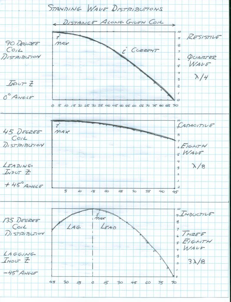
It's not a normal antenna. It has a normal quarter wave voltage and current distribution LIKE an antenna.
What has been measured happens to match what Eric said it should be, and was provided in the context of and with all the other relevant data. You have shown what yours is, but frankly I'm not convinced for a number of reasons.
You have still not said what the voltage distribution on your coil is, nor the intended design frequency, nor the conductor length or anything else. Others have measured the same thing as I have shown, so you are the odd one out with your measurements, which leads one to suspect that something must be wrong.
And the fact still remains that the probe you are using to measure the coil is too close so is having an effect on the coil and therefore the measurements, as well as the additional capacitance terminal tube which isn't supposed to be a part of the design either. Until these are addressed and the coil is reverted back to default then it's no use telling me that I've built my coils wrong.Leave a comment:
-
Eric seems to contradict himself more better try to understand why it should be the one way or the other. I would point to the Borderlands video where Eric measures the voltage on a Tesla coil and calls it an analogue of the longitudional network.
When I think of this myself I see no reason why it would be a normal antenna with the capacity between the turns.
Just for fun do a search on lefthanded transmission lines and backward waves and stop parroting thing you do not understand
Leave a comment:
-
You are overlooking the fact that Eric has been here and looked over all these results and data himself. (On the forum, not my house).
Also you are not saying what the voltage distribution is.
Optimal turn spacing = 62% conductor diameter.
And again again again, the vacuum tube and meter should be removed from direct contact with the secondary as you are not measuring the coil's natural behaviour when they are connected.

 Last edited by dR-Green; 06-28-2015, 02:54 PM.
Leave a comment:
-
I made a simulation with very small vallues for the mutual capacitance and the mutual inductance. Not surprisingly the coil behaves transversal now.
The maximum resonance is the first and I plot the current in coil 4 (green) and coil 13 (red). The current in coil 4 is bigger than in coil 13. The magnetic field is now in space disjunction with the electric field.
This all is very difficult to understand and I will start a new thread with all the plots quotes measurements and simulations.
For now this simulation shows a normal 1/4 wave distribution because K and M are small.

Leave a comment:
Leave a comment: