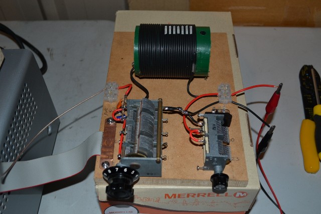
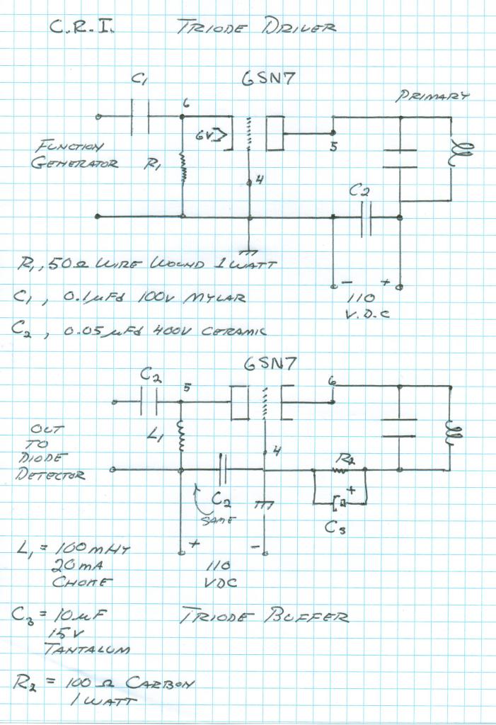
Thanks! Yes it is all new to me. I lost most time trying to build the tube driver.
You mentioned that the plate current was dipped at optimum load. I realised that I did not measure the plate current so I tried a mA meter between the dc power and the anode but that gave me 10mA and nothing dipped.
So please could you help me out what current I have to measure to dip the plates?
This is my grounded grid driver.
Announcement
Collapse
No announcement yet.
Eric Dollard
Collapse
This is a sticky topic.
X
X
-
Originally posted by orgonaut314 View PostNicely done and good description for everyone to try. However the resonance of the primary tank depends on the frequency so I first find the resonance of my primary with secondary and than try to develop my impedance network having a maximum at the same frequency. I use a L matching network.
However my latest try had a resonance of the coil at 3,2MHz but with the L-network the resonance was at 2,8MHz so I think I still not have the right coil value because I adjust the cap. I have a variabel coil that I can connect to further optimise the radiation.
My work is not as nice as yours but I am learning
For instance my secondary coil with a given terminal capacitance has a Ro of 2.08Mcps. (Measured by driving the base of the secondary coil with a low power transistor oscillator directly and hunting for the Ro). Again while driving the base of the secondary, placing the secondary coil within the primary loops even without the tank capacitor connected, brings down the Ro a bit more.
Adding in the tank variable capacitor alters it once again. Adjusting the variable tank capacitor also affects the Ro of the secondary, while driving it from the base. I simply played about with the frequency and variable tank capacitor until I found the frequency that provided the strongest Ro, while adjusting the tank capacitor setting.. So then that frequency was used to base the Pi network on. Then with the higher power tube transmitter using that determined frequency, with slight adjustments here and there on the Pi network and such, resonance was achieved. It worked out to be ~1.97Mcps. There is a distinct drop in plate current when resonance is found.
Likely its still best to listen to what JP or Eric have said about coil tuning, rather than me.
So looking at the picture of your arrangement, I can’t see anything that you are doing majorly wrong. It seems fine. I could suggest (which I will try with mine at some point) adding in some extra tap points to your L-network coil (if you haven’t already). You may find a more optimal L- network coil inductance for a given frequency. So what you’re doing is fine it’s just a matter getting it roughly right and then via trial and error you’ll find the optimal settings.
Your work is great! The thing is that you have actually bothered to build something! In fact it’s an entire Tesla coil rig based on Eric’s teachings. There is so much to learn in all of this: Power supplies, transmitters, coils, Impedance-networks, tuning, displacement current, Resonance, Maths, etc, etc. So you’ve done great and you should keep going. I’m sure you’ve learned a great deal from when you started. So have I.
What you have done represents the tiny handful of experimenters on the planet that have actually made something and shown their work publically regarding Tesla coil design and function, as Eric Dollard has taught! – Which by the way, is a sh##-load more than what most other people have done.
It doesn’t have to look pretty or highly polished (after all it’s experimental). The main thing is that it you’ve had a crack at it and produced something is actually started to work. So you’ve done well and are on the list of the small group of people who have done so. It would be nice if there were more of us... Probably as a reuslt you’re now also on one of those other “watch-lists” Haha.
Leave a comment:
-
Nicely done and good description for everyone to try. However the resonance of the primary tank depends on the frequency so I first find the resonance of my primary with secondary and than try to develop my impedance network having a maximum at the same frequency. I use a L matching network.
However my latest try had a resonance of the coil at 3,2MHz but with the L-network the resonance was at 2,8MHz so I think I still not have the right coil value because I adjust the cap. I have a variabel coil that I can connect to further optimise the radiation.
My work is not as nice as yours but I am learning
Last edited by orgonaut314; 05-27-2015, 04:16 PM.
Leave a comment:
-
Z match
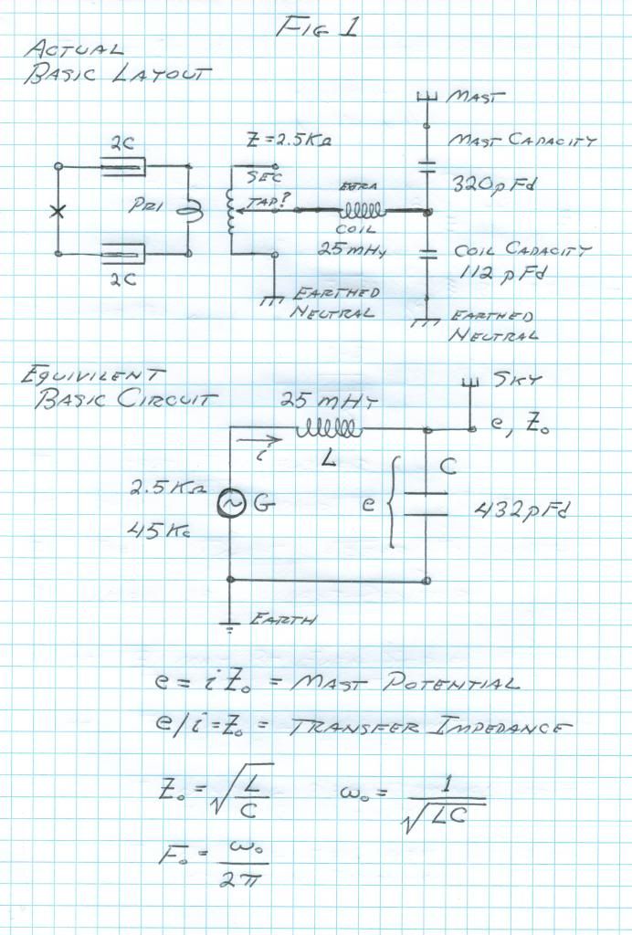
Originally posted by orgonaut314 View PostYes thanks I now get the elevated capacity. The tuning of the extra coil is something I am hesitating on. I now have a system without extra coil with tube driver and that I understand.
One thing on the impedance matching between tubes driver and the system with an extra coil. Perhaps the extra coil raises the impedance? I edited my calculations that where wrong. I have no idea how to calculate the impedance seen by the driver but I can measure it. It was low like 500 Ohm.
That is another reason to try the extra coil this time.
Picture comes from coil compendium thread.
So remove all of the coils and drive the primary tank circuit on its own. (Or you could say you have a extremely light coupling). Of course there will be an impedance mismatch between your transmitter and the tank circuit. Thus you’ll require an impedance matching network, preferably one that’s variable. There are a few ways to achieve this. I found with my transmitter, since it is “single ended”, I found a Pi Network worked best for my situation. (Pi Network not much use for push pull drivers though). So once you can achieve efficient transfer to your primary tank then you can reintroduce the coils. Of course then the impedance will change, but not so much that you can’t adjust for it with the Pi Network. Small adjustments are needed as you vary frequency, add loads etc.
My Pi network was built from two air variable capacitors (750 - 1000pF each I think) and a coil about 32uH.
So research Pi networks (ham radio), impedance matching, for some background. (Baluns, & magnetic loop antennas hold some useful info to).
Remember what Eric wrote:
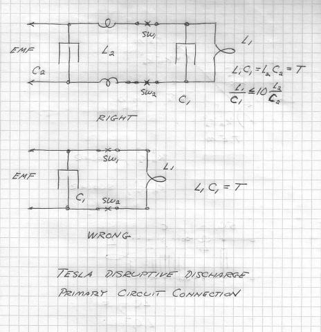
The Primary Circuit, First
We begin with the "Primary Circuit." It is a parallel resonant circuit. This exists in the dimension of time, it is space scalar. Hence no T.E.M., etc. Time only in Neper-Radians per second. PER SECOND. It should be noted that no generalized analysis of this circuit even exists today, so where do YOU want to begin. I will tell you how, get a 1960's Radio Amateur's Handbook, and read it. Then make a 100 watt 80 meter transmitter. Then you can begin to understand Tesla. Throw all the Bearden, Corum, etc. , into the garbage, let the rats and crows have it.
The circuit I have shown is from the Colorado Springs Notes, read this for circuit values, these can be scaled. The reasoning here is that no resistance is wanted in the main tank circuit (L1,C1), it must be tight against leaks to assure maximum magnification factor. The Auxilary Circuit (L2,C2) is an impedance matching network to carry energy from the supply E.M.F. to the tank circuit M.M.F. The energy in L2 C2 refracts into L1 C1 so as not to disturb the primary M.M.F. This M.M.F. the maximized to the highest possible magnitude.
Leave a comment:
-
Yes thanks I now get the elevated capacity. The tuning of the extra coil is something I am hesitating on. I now have a system without extra coil with tube driver and that I understand.
One thing on the impedance matching between tubes driver and the system with an extra coil. Perhaps the extra coil raises the impedance? I edited my calculations that where wrong. I have no idea how to calculate the impedance seen by the driver but I can measure it. It was low like 500 Ohm.
That is another reason to try the extra coil this time.
Picture comes from coil compendium thread.Last edited by orgonaut314; 05-26-2015, 09:58 AM.
Leave a comment:
-
Originally posted by orgonaut314 View PostThanks Sputins.
If I remember well you also made flat coils. Did you use the same 62% wire spacing there in the secondary? I am thinking of making a flat coil that will not be useful with an extra coil but might make a better simple telluric system?
Also I have a question about tuning the extra coil. In the original drawing Eric showed the extra coil with its elevated capacity coupled to a plate that was connected to earth. Now I wonder if the tuning was done without the extra plate. Perhaps the extra plate was tuned to resonate with the extra coil? I see no descriptions of that final tuning stage. Was the capacitor large enough etc. I wonder what drGreen did there. Perhaps we could just leave the extra plate and operate the extra coil just as an extension of the secondary coil?
The secondary coils can be used on their own for Telluric work. (Receiving or Transmitting). It certainly is much simpler to get a feel for what’s happening. Then the only variables to play with are the tuning frequency and primary tank, the coupling distance between the primary and secondary, together with the top terminal capacity, size and elevation.
If you’re driving the coils with a transmitter then the impedance match between the transmitter output and the primary tank becomes an important factor too.
I think you will find the plate connected to ground, coupled with the extra coil is brought closer or nearer to the elevated capacity in order to help tune the overall system. This is because as this grounded plate is brought closer or nearer it alters the capacitance of the elevated capacity, thus changing the tuning of the whole system. A similar concept is when a highly tuned coil will de-tune when you bring you hand near it. A coil can also be off tuned so that it becomes tuned when you hand is brought near. This is the main purpose of the grounded plate next to the elevated capacity. (Although in one of Eric’s receiving circuits it’s also used to help pick up the signal from the coils). You could achieve a similar result by adjusting the height of the elevated capacity, its size, shape, or material etc.
So you juggle all of the above variables in order to maximise the Telluric output or input. So there’s enough variables to adjust and play with, without adding in the complication of an extra coil. Add in an Extra coil once you’ve mastered and maximised the result from Secondary coil on its own, would be my suggestion.
Leave a comment:
-
Thanks Sputins.
If I remember well you also made flat coils. Did you use the same 62% wire spacing there in the secondary? I am thinking of making a flat coil that will not be useful with an extra coil but might make a better simple telluric system?
Also I have a question about tuning the extra coil. In the original drawing Eric showed the extra coil with its elevated capacity coupled to a plate that was connected to earth. Now I wonder if the tuning was done without the extra plate. Perhaps the extra plate was tuned to resonate with the extra coil? I see no descriptions of that final tuning stage. Was the capacitor large enough etc. I wonder what drGreen did there. Perhaps we could just leave the extra plate and operate the extra coil just as an extension of the secondary coil?
Leave a comment:
-
Originally posted by orgonaut314 View PostI am going to build another coil. When going through the numbers I was thinking that the easiest way to match the mass of secundairy and primairy coil would be to use a certain wire size like 14 awg that has the 68% spacing with the given coil height and than using 10 strands of 14 awg in the primairy. That way the mass will be equal as the secundairy uses 10 times the number of windings of the primary.
Now eric says to use sheetmetal for the primary. Polakowsky uses coax. If I use solid wire the surface will be the same as coax the only difference is that I have a lot of unused coper because of the skineffect. But coax is more expensive than solid wire so 14 awg for everything seems to me the simplest way. Am I missing something?
It seems Eric does not like solid wire that has a big diameter but I can not find why that is.
I think you will find that JP used copper tube for the primary and coax for the secondary. His copper tube primary looks much thinner than quarter inch, maybe 3/16”?
I think you have the right idea, make your secondary and match the primary mass to suit. I did it by actual weight of the copper, I.e. I stripped the copper out 1 meter coax of cable I used for the secondary and weighted it. I tried to match the total mass of copper in the secondary coil with the total mass of copper in the primary coil. My primary coil worked out overweight I.e. More copper mass in it than ideal, because I used the Cu tube that I had on hand, although using only two turns brings it close. Adding the extra coil copper weight brings it ever closer. (Not sure if one counts the extra coil, due to it not being directly connected).
I would speculate that at low frequencies (30Kcps) it is mass that is more important but as the frequency increases, (2Mhz-up) then surface area matters more due to the increased skin effect?
So I would suggest using whatever is simplest and you can afford. If the primary is too heavy it’s likely better than being too light, simply because if you power it with a decent amount of power, you’ll have many amps of circulating current in the primary system.
It will work whatever you do, but finding out what is optimal is the trick.
Leave a comment:
-
Originally posted by skribat View Post---------------
Perhaps it has something to do with the ratio of surface area to volume/mass which changes with the diameter, (awg)
I include the post where Eric advises a compromise between wire thickness and wire spacing.
Originally posted by ericOriginally posted by Web000xEric,
I am having trouble understanding how you chose 14 gauge wire to be suitable for the secondary winding for 1000 Kc per second transmitter. When I used your formula given above for the (6) "Maximum Solid Conductor Diameter", It gives me 0.51 mm, the equivalent of 24 gauge. 14 gauge is 1.63 mm in diameter. It would seem that the 14 gauge as prescribed by you is larger than the maximum diameter according to your formula at 1000 Kc per second.
The 14 gauge is the best compromise size. That way no fancy coax, you still have enough surface area to keep the magnification factor high. Obviously 8 gauge would have to be hollow to be useful. Remember the frequency given is approximate. Someone is going to have to build one to see how far off it is. Examine closely the frequencies in the Extra Coil in the Tesla Colorado Springs Notes, very closely. In the Theory of Wireless Power use the design equations to find the characteristics of the coils I presented in these recent presentations of the Crystal Radio Initiative.
max solid diameter: 0,51mm (two times skindepth)
hollow diameter:4,8mm (because spacing must be 62%)
Eric advises 14awg = 1,6mm because it has still enough surface and it is 6 times the skindepth.
Now i have to scale these compromises to my 3MHz coil
Leave a comment:
-
Originally posted by mikrovolt View PostBroMikey
The music was written in Tesla's time. He may have been sensitive to sound. When he wasn't blasting arcs and so forth.
The video shows some oscilloscope signals that a musician might
visually examine and understand the nature of parasitic waves act in a large motor.
Hi Mikro
Check out vibrational technology today.
https://www.youtube.com/watch?v=bOALsthpa5A
Leave a comment:
-
Originally posted by orgonaut314 View PostI am going to build another coil. When going through the numbers I was thinking that the easiest way to match the mass of secundairy and primairy coil would be to use a certain wire size like 14 awg that has the 68% spacing with the given coil height and than using 10 strands of 14 awg in the primairy. That way the mass will be equal as the secundairy uses 10 times the number of windings of the primary.
Now eric says to use sheetmetal for the primary. Polakowsky uses coax. If I use solid wire the surface will be the same as coax the only difference is that I have a lot of unused coper because of the skineffect. But coax is more expensive than solid wire so 14 awg for everything seems to me the simplest way. Am I missing something?
It seems Eric does not like solid wire that has a big diameter but I can not find why that is.
Perhaps it has something to do with the ratio of surface area to volume/mass which changes with the diameter, (awg)
Leave a comment:
-
Choice of wire for new coil project
I am going to build another coil. When going through the numbers I was thinking that the easiest way to match the mass of secundairy and primairy coil would be to use a certain wire size like 14 awg that has the 68% spacing with the given coil height and than using 10 strands of 14 awg in the primairy. That way the mass will be equal as the secundairy uses 10 times the number of windings of the primary.
Now eric says to use sheetmetal for the primary. Polakowsky uses coax. If I use solid wire the surface will be the same as coax the only difference is that I have a lot of unused coper because of the skineffect. But coax is more expensive than solid wire so 14 awg for everything seems to me the simplest way. Am I missing something?
It seems Eric does not like solid wire that has a big diameter but I can not find why that is.Last edited by orgonaut314; 05-22-2015, 10:54 AM.
Leave a comment:
-
Originally posted by Aaron View PostINTERVIEW ON J.J. THOMSON
J.J. Thomson - hear Eric give a brief overview about this man who is as important as Tesla but not many people understand his work. If you want to know the real physics of the aether, studying J.J. Thomson is a must: 2015-03-30 Eric Dollard on J.J. Thomson - Eric P. Dollard - Official Homepage
See previous posts, What is AREA 52-E? and the Interview on JJ Thompson.
The Area 52-E, a narrated power point really shows how far the Advanced Seismic Warning System has come thus far. It is actually becoming a reality. The glom and other windows of opportunity that have opened up for this project as if by magic, are indeed encouraging and exiting. Although not really by magic but by the hard work by the people actually working on it or around it.
The INTERVIEW ON J.J. THOMSON is remarkable. Given here, in words directly or reading between them, presents some of the most remarkable information currently available on this topic. This interview if fully comprehended is mind blowing. This is why no one can top Eric Dollard for relaying this kind of information relating to Electrical Science. Here is 100% golden material.
Leave a comment:
-
Tesla:
"First was energy, then matter".
"What about the birth of the Universe? Matter is created from the original and eternal energy that we know as Light .It shone, and there have been appear star, the planets, man, and everything on the Earth and in the Universe. Matter is an expression of infinite forms of Light, because energy is older than it. There are four laws of Creation. The first is that the source of all the baffling, dark plot that the mind cannot conceive, or mathematics measure. In that plot fit the whole Universe".
"The second law is spreading a darkness, which is the true nature of Light, from the inexplicable and it’s transformed into the Light. The third law is the necessity of the Light to become a matter of Light. The fourth law is: no beginning and no end; three previous laws always take place and the Creation is eternal".
"Remember, it is not curved space, but the human mind which cannot comprehend infinity and eternity! If relativity has been clearly understood by its Creator, he would gain immortality, even yet physically, if he is pleased.
I am part of a light, and it is the music. The Light fills my six senses: I see it, hear, feel, smell, touch and think. Thinking of it means my sixth sense. Particles of Light are written note. O bolt of lightning can be an entire sonata. A thousand balls of lightning is a concert"..
"For this concert I have created a Ball Lightning, which can be heard on the icy peaks of the Himalayas. About Pythagoras and mathematics a scientist may not and must not infringe of these two. Numbers and equations are signs that mark the music of the spheres. If Einstein had heard these sounds, he would not create theories of relativity. These sounds are the messages to the mind that life has meaning, that the Universe exists in perfect harmony, and its beauty is the cause and effect of Creation. This music is the eternal cycle of stellar heavens".
"The smallest star has completed composition and also, part of the celestial symphony. The man’s heartbeats are part of the symphony on the Earth. Newton learned that the secret is in geometric arrangement and motion of celestial bodies. He recognized that the supreme law of harmony exists in the Universe. The curved space is chaos, chaos is not music. Einstein is the messenger of the time of sound and fury".
"Everything is Electricity. First was the light, endless source from which points out material and distribute it in all forms that represent the Universe and the Earth with all its aspects of life. Black is the true face of Light, only we do not see this. It is remarkable grace to man and other creatures. One of its particles possesses light, thermal, nuclear, radiation, chemical, mechanical and an unidentified energy".
"It has the power to run the Earth with its orbit. It is true Archimedean lever".
"Do everything that any day, any moment, if possible, not to forget who we are and why we are on Earth. Extraordinary people who are struggling with illness, privation, or the society which hurts them with its stupidity, misunderstanding, persecution and other problems which the country is full of a swamps with insects, leaves behind unclaimed until the end of the work. There are many fallen angels on Earth".
Nikola Tesla – Everything is the Light » Stankov's Universal Law Press
Leave a comment:
-
LMD & Spark Gap Energy Synthesis
LMD & Spark Gap Energy Synthesis:
Aaron,
Thanks!
Quote:
"Right now is a good time to post all questions in this thread right now as Justin has a laptop with him and internet connection. I can't promise Eric has time to look at all of this, but post away!"
Question for Eric:
Noticed on his bench an LMD of L & C with large L and looked as if it were wound on a Ferrite or Toroid.
Just interested in what he is constructing if he could please elaborate on the design and purpose of that particular unit?
TEM/LMD Tests JL Naudin:
The L.M.D./T.E.M.Test
About to do some work on the LMD array as I have a theory about the capacitance being used as having insufficient capacity to achieve a much better OU result as I found out with the high voltage Cockcroft-Walton voltage multiplier chain.
This could also apply to the Inductor being used.
What is also of interest is the work of Bill Alek of Intalek and his tests on spark gaps and the OU achieved:
Multi-Spark Gap Experiments
Going to meld these two together as a project as it requires further investigation as it is the two basics of many drivers for coils including the Tesla Magnifying Transmitter (TMT) or in our case, the Crystal Set Initiative (CSI)
Fran De Aquino Gravitational Energy into Electrical Energy (GEEE):
Configuring HT supplies but work is slow due to other commitments and mainly to do with weather engineering.
Going to use a 10kv 30mA Neon Sign transformer for the 8kv with a Blaupunkt TV Focus resistor 100megohm bleed for the 4kv (untried).
Setting up the 80watt resistors for the implosion waveguide.
One of the pictures used to display Eric's work was of my CSI being driven by his 6SN7 driver.
The Copper coil dangling was connected to a probe to the oscilloscope and would like to present that picture again as I am still mystified by the result:
This is a radiation from the unit but not sure of its nature.
Need to get back into this area of research as it is the only way to achieve some kind of an understanding.
Smokey
Leave a comment:
Leave a comment: