Announcement

Collapse
No announcement yet.

Eric Dollard

Collapse
This is a sticky topic.
X
X
 
  • Filter
  • Time
  • Show
Clear All
new posts

  • Originally posted by mr.clean View Post
    hi there, excellent work!

    so you actually were the one who met with Eric?

    i was sad to hear Eric ask "why should people be interested in me?"
    or something along those lines.
    He needs to know we love him very much.

    Despite him having lost everything on several occasions, I just know that Eric will give it ONE more try if we can hook him up,
    Or like it was mentioned, to get him back his equipment... but there is actually a known location of it all?

    anyway, hey WOULDNT IT BE AWESOME TO HAVE AN ERIC DOLLARD TV SHOW??

    the guy could go on perpetually about relevant issues if just speaking let alone demonstrations and R&D.

    just think, even if he only had internet, to be HERE answering questions or whatever... imagine the possibilities if "Tesla" himself could give advice... with todays modern components?

    anyway, are you the guy who met with Eric in person?

    YOU really played an extraordinary role in giving us these recent videos, and it may be ALL because of YOU that literally SAVED Eric's life at this unimaginably hard time for Eric.
    It really brings tears of joy to know all this
    Thankyou
    Thank you. yes I went to see him. Was an archetypal scenario. Felt like going to see Yoda. Eric like Sky Walker too in that he still has that youthful enthusiasm running through him. We just need to protect him while he weaves his spells and keep the scum away from him, then amazing things can happen.

    Eric has more personality than all of Hollywood's fake creations combined. He made me laugh out loud many times.
    Last edited by techzombie; 02-05-2013, 11:12 AM.
    Banned For Illegal Activities / Fraud

    Comment


    • Originally posted by David G Dawson View Post
      Hello Clarence,
      Thankyou for your interest.
      I receive an Email whenever a new Post is presented here and that Email gave the corrupted as well as an uncorrupted URL which I clicked on and had no problems going to the site and downloading again, just to make sure.
      Here it is again:

      За сваляне на филми използвайте бутонa [MIRROR 1] - Електричество (Electricity) - The Cosmic Collector

      Somewhere in the setup page you can click on to receive the Posted Email notification and this may also be worth a try.

      Hope this helps.

      Smokey.
      Hello David G Dawson,

      clarence,

      just to let you know thay I did finaly download the cosmic collector info and to thank you for efforts. THAT info is awesome! did dollard have anything to do with that?

      the reason I was wanting the info was my plan to build Teslas radient energy device, this cosmic collector is definitely a parallel device to tesla's I think! thanks again. mike onward!

      Comment


      • Pictures on Page

        dR-Green,
        Many thanks for explaining the operations required but don't remember seeing the 'i' until this time and might be that an Album is required.
        Your efforts most appreciated.

        techzombie,
        Many thanks for the Eric videos and was good to hear of Philo T Farnsworth
        and how he was also manipulated by the corporations.
        Don't ever think of Eric Dollard going on TV as that is what Philo was most disgusted about and probably Eric too.
        A medium where you extract money for this infernal advertising that we get imploded into our faces at every opportunity through radio, tv, newspapers, roadsides and your computer screen - this is not what Philo had in mind for his invention of television - money and advertising!
        Wait until you are able to retire and you will suddenly understand and will only have the television on for only what you really want to see - lack of substance is the problem.

        clarence,
        Good that you got the data.
        Eric is being most responsive to some of my requests for information and that covers, 'The Integratron' of George Van Tassel and now Philo T Farnsworth as he was involved personally with both of those individuals.
        Eric is also into Vacuum Tubes and has given several schematics that we are using to build particular devices to help in making our 'Star' and work with the Tesla Magnifying Transmitter.

        Eric is, I am told not into or fully aware of other well known researchers like, Hubbard, Hendershot, Stubblefield etc.
        Eric is not computer literate and the reason for trying to get pictures here on the page to help him see our efforts and correct our errors.
        Because I am into Thomas Henry Moray, this is where 'The Cosmic Collector' came from.

        Now that I am, at long last, able to present pictures on the page will do so as the moment arises.
        Thanks.

        Smokey

        Comment


        • Originally posted by David G Dawson View Post
          dR-Green,


          clarence,
          Good that you got the data.
          Eric is being most responsive to some of my requests for information and that covers, 'The Integratron' of George Van Tassel and now Philo T Farnsworth as he was involved personally with both of those individuals.
          Eric is also into Vacuum Tubes and has given several schematics that we are using to build particular devices to help in making our 'Star' and work with the Tesla Magnifying Transmitter.


          Now that I am, at long last, able to present pictures on the page will do so as the moment arises.
          Thanks.

          Smokey
          Hello David G Dawson,

          clarence,

          many thanks again to you for you continuing valuable efforts Sir!

          mike,onward!

          Comment


          • Originally posted by techzombie View Post
            new Video of Eric.
            He reveals real technical data about Farnsworth's working fusor.

            https://www.youtube.com/watch?v=64sVDmhIUbI
            Hello techzombie,

            clarence,

            first of all many thanks to you and your immense efforts with respect to Eric Dollard and his amazeing videos. I am being a donor to the site for him.

            when you next contact him I have a question you might ask him if possible. I am in final process of completeing the central part ( L1 & L2) of the don smith proof of concept device (basicaly the tesla magnifying transformer setup) which has the central transmitter with receiver and 4 ea additional receivers. the block diagram would be BATT - INVERTOR DRIVER - L1 TRANSMITTER - L2 RECEIVER (with the batt being continuosly recharged by the 1/4 wave wire length relationship of batt + supply lead and the L1 coil wire length constituteing a self running system).

            The only problem I have had in all of my efforts is a suitable variable frequency & set sine voltage DRIVER to operate the Tesla coils and extract the available aether energy.

            At present I have built an AC output inverter from DC batt and incorporated a variable frequency means in it with a 50% duty cycle that will give me 35.1 KHZ and voltage of 372v . It has taken time to come up with this arrangement and if this is the ultimate way to do it I will learn to live with it!
            however I was wodering if ERIC would know of a simpler way to make an effective driver? and that is the question I was hopeing you might be able to as of him and his mighty resourceful mind.

            thanks in advance for your considerations and efforts Sir.

            as always, mike, onward!

            Comment


            • Cosmic Ray Detector

              Cosmic Ray Detector is now complete with Eric's new mods and have now added the two bells:


              Rear view shows my conclusion as to how to make the donger arm a part of the switch as I have now removed the manual reset relay from the top.
              The Western Electric coil and donger arrangement is well made and the donger sits central without contacting either side.
              The solution for the donger arm to be the switch was to place two small 3/16" x 5/16" Neo magnets directly either side of the fulcrum point above the core contacts so that it now will make contact with either side sufficiently such that the electromagnet being powered will still affect the donger.
              You can see the small Neos on the fulcrum arm.
              Tried to make contact with the arm with spring steel but was most unreliable and affected its operation but the final solution was simple:


              Eric is saying the 0A4G is Neon gas filled but disagree as it is Argon and this from both the picture of an actual test on my Heathkit IT-17 Tube Checker and also from other material at hand.
              It is difficult obtaining this exact information as to what is actually being used as they appear to want you to know that it is only a gas or vapour:


              Next step is to do some experiments with the 0A4G as Eric has suggested and this is from Post 348 of the old Eric Dollard Forum and had to dig out some of my Mica Capacitors.
              The Large Ducon has written on its side 'NBG' which is Oz slang for 'No Bloody Good' and yes it has a blow out internally but is still OK for use with reduced voltage and have noted the new value on the top but can also be refurbished.
              This would be out of an AM transmitter as where most of the larger sizes would also be sourced from:


              These are the UK Cintel Geiger Muller Tubes I will be using as my 'receptor' for the Cosmic Rays and is a very simple Tube and is what Bruce Perrault has as an 'Ion Valve' but this one is filled with an unknown gas/vapour, where the earlier experimental types were filled with an Argon/Oxygen mixture.
              Reading from the manufacturer's data and these Tubes were all hand made and calibrated with the Anode being a Tungsten wire through the middle and a thin Copper sleeve as the Cathode - lots of surface area.


              Jerry Bales Resonant Tubes:
              Have now a means for amplifying the frequency and this is going to come from a 50Watt 'BoomBox' which has a Microphone mixing facility on the back.
              So this means to deadband the Radio and simply plug in the Signal Generator and stand back.
              Will put up some pics when assembled.

              Hope the pictures are presented correctly.
              Thanks.
              Last edited by David G Dawson; 02-05-2013, 04:41 AM. Reason: pics out of order

              Comment


              • Gerry Vassilatos Videos

                First of all, techzombie, great work on everything you've done promoting Eric's work, creating a site for him & raising money for a new lab! I've really been enjoying the videos, look forward to new ones all the time!

                I believe this is the best place to post these on Energetic Forum and also think Eric may enjoy them. I received two Gerry Vassilatos videos from a friend on VHS to rip to a format that can be posted online to share with everyone. I don't think these are even available anywhere anymore. I've posted them to concen.org & piratebay.se, I know some don't care to create an account on concen & others are worried about viruses from piratebay (although I've never got one or I wouldn't use it). Complimentary to the Vril Compendium, especailly the Aura Motors.

                I hope these are of interest to the group.

                Aura Motors - Gerry Vassilatos (~1998): Aura Motors - Gerry Vassilatos (~1998) (download torrent) - TPB

                Teslas New York - Gerry Vassilatos: Tesla's New York - Gerry Vassilatos (download torrent) - TPB

                Aura Motors - Gerry Vassilatos (~1998): http://concen.org/tracker/torrents-details.php?id=31948

                Teslas New York - Gerry Vassilatos: http://concen.org/tracker/torrents-details.php?id=31947

                Comment


                • Originally posted by David G Dawson View Post
                  dR-Green,
                  Many thanks for explaining the operations required but don't remember seeing the 'i' until this time and might be that an Album is required.
                  Your efforts most appreciated.
                  No problem. Although I haven't made any album that I'm aware of, the button isn't obvious anyway, I only found it by hovering the mouse pointer over them all and waiting to see what the popup said.

                  In other news: First success with lighting incandescent bulbs on the ground end of TMT with relatively low power. A second amplifier stage has been added after the stage that was previously tested. Also a primary condenser has been added to the single turn test coil, but this is currently tuned to a higher harmonic.

                  Signal generator F = 3080 kc
                  C = approx 600pF
                  Power supply = +/- 10.9V DC (no load, 500mA max transformer output)
                  R = 30 ohms (limiter)
                  Imax = 363mA
                  Single turn test coil calculated impedance from F and L = Approx 13 ohms
                  Measured current through single turn test coil = 210mA (not RF ammeter, no load)
                  Measured voltage across single turn test coil = approx +/- 6V
                  Measured current from secondary output (ground end) to earth = 230mA (not RF ammeter, no load)
                  Taking 210mA and 6V as approximate values, power supplied to single turn test coil = approx 1.26 watts. Single turn test coil impedance would therefore have to be approx 28 ohms.

                  These values are taken "as is", no power factor correction and what not.

                  Bulbs tested:
                  "Grain of rice" - 1.5V 20mA 30mW
                  #673 - 6V 60mA 360mW
                  #327 - 28V 40mA 1.12W

                  "Grain of rice":


                  #673:


                  #327:


                  Other (low voltage) bulbs were also tested but of the ones tried so far only these three worked.

                  Scope across single turn test coil:

                  Last edited by dR-Green; 02-05-2013, 01:46 PM.
                  http://www.teslascientific.com/

                  "Knowledge is cosmic. It does not evolve or unfold in man. Man unfolds to an awareness of it. He gradually discovers it." - Walter Russell

                  "Once men died for Truth, but now Truth dies at the hands of men." - Manly P. Hall

                  Comment


                  • Want to Add new Perks for the Campaign and looking for suggestions from the elite folks on here. Please feel free to suggest works to be added to these collections.

                    1. Eric Dollard "Transmission" Lone Pine Writings

                    2. The Collected Papers of Eric Dollard
                    -Condensed intro to Tesla Transformers by Eric Dollard
                    -Teluric Currents Paper
                    -Introduction to Dielectric & Magnetic Discharges in Electrical Windings, Electrical Oscillation
                    -Symbolic Representation of the Generalized Electric Wave
                    -Theory of Wireless Power
                    -Symbolic Representation of Alternating Electric Waves by Eric Dollard
                    -Free-Energy Research of Eric Dollard - Notes (1986-1991)


                    3. Lost Science Collection
                    -Lost Science, Cold War Secrets, Vril Comp by Gerry Vassilatos
                    -Prodigal Genius Biography of Nikola Tesla by John O'Neil
                    -Etheric Formative Forces in Cosmos, Earth and Man by Guenther Wachsmuth
                    -Man or Matter Ernst Lehrs
                    -The Inventions Researches and Writings of Nikola Tesla
                    -TESLA Lecture-Before-the-New-York-Academy-of-Sciences-Apri-6-1897
                    -The Ether of Space by Sir Oliver Lodge
                    -History of the Theories of Aether and Electricity Vol 1/2 - Whitaker

                    4. Aether Mage Training Pack
                    -The Transmissions of Eric Dollard
                    -Radio Amatuers Handbook 1946
                    -Radiotron Designers Handbook 4th edition (1954) RCA
                    -Electricity and Matter by JJ Thompson
                    -A-Treatise-on-Electricity-and-Magnetism-VOL-1-by-James-Clerk-Maxwell
                    -Oliver-Heaviside-Electromagnetic-Theory-Vol-1
                    -Electrical Waves Discharges Steinmetz
                    Banned For Illegal Activities / Fraud

                    Comment


                    • Tesla Books - 911 Twin Towers

                      'The Wall Of Light' by Arthur H Matthews on Nikola Tesla and The Venusian Space Ship 'The X-12' arrived today and will pass on any information contained that may be of interest.

                      This is one of the books on Tesla that you hear very little about but is filled with the only hinted at devices that Tesla discovered and as related by Arthur as he was there as an assistant to Tesla and as a friend.
                      My observation that Tesla was financially secure is proven correct in this book and he was being paid handsomely by those that wanted him out of the limelight whilst they made millions from his inventions.

                      Could not find a copy on the Net but did find Margaret Cheney's book on Tesla - 'Man Out Of Time':

                      http://biotu.org/download/ecoaldea/e...20(Cheney).pdf

                      Another book of interest on Tesla is 'Lightning In His Hand' and if you go to this URL you will see it mentioned towards the bottom of page:

                      hello-earth.com ~ Venus Tesla Connection ~ Tesla Oscillator Shakes New York City ~ Then and Now

                      Here you will see extracts from a book by Dinshah P Ghadiali called 'Spectro-Chrome Metry Encyclopedia' and this relates to Tesla's Mechanical Oscillator device and how the 911 Twin Towers were demolished without explosives and in the same space.

                      '7redorbs and 'Arto' may be interested in this chart even without the book.
                      Could not find a free copy but have both above books on an Amazon wish list which they will come back to me after a while with a special offer.

                      Somewhere in that book is the frequency and the listing equates with that frequency.
                      What was it, does anyone know and you will need to have that book to find out?
                      Going to have a stab and say it is # 20 - Highest Etherial Sound at 1,048,576hertz.

                      Why? - believe this is where the atoms all come apart and nothing can be held together any further or longer because we then get into rays and this is the last of the solid matter line - you end up with just dust and isn't that exactly what happened in New York?
                      Even the lowest etherial sound may be sufficient at 65,536 hertz.
                      Water dissociates at 42,800 hertz, the frequency where the liquid is simply no longer able to hold together.
                      Arthur covers this device in his book.

                      Smokey

                      Comment


                      • Originally posted by David G Dawson View Post
                        Somewhere in that book is the frequency and the listing equates with that frequency.
                        What was it, does anyone know and you will need to have that book to find out?
                        Going to have a stab and say it is # 20 - Highest Etherial Sound at 1,048,576hertz.

                        Why? - believe this is where the atoms all come apart and nothing can be held together any further or longer because we then get into rays and this is the last of the solid matter line - you end up with just dust and isn't that exactly what happened in New York?
                        Even the lowest etherial sound may be sufficient at 65,536 hertz.
                        Water dissociates at 42,800 hertz, the frequency where the liquid is simply no longer able to hold together.
                        Arthur covers this device in his book.

                        Smokey
                        What about MHZ range ultrasonic transducers? Here is a company which sells ultrasonic transducers up to 225Mhz.

                        Comment


                        • The recent experiments have mostly been focused on the power supply rather than the coil(s), the plan is to devise a circuit capable of supplying a decent amount of power using "modern" components, at minimal cost and in some aspects completely free (thanks Texas Instruments). This mainly to have control over the power that's being supplied to the coil, both the current and the voltage. Results so far have been good and the power is gradually being increased, however as it stands the only "reliable" means of judging the supply power level is by the temperature of the components. At the moment I would say that the power is quite minimal, the transistors barely getting warm and the 500mA transformer barely producing any noticeable heat. "Well within limits" sums it up. Vin = +/- 10.9V, 22 ohms limiting resistance.

                          The most promising sign is that small bulbs are now starting to light up with a single wire, which I had considered to be quite a difficult task due to the characteristics of the bulbs and the low voltage being used. The main difference between the previous test is that a (relatively large) terminal capacitance was added to the extra coil with a small bulb in series as described in one of Tesla's Colorado Springs experiments (with picture in CS Notes). The bulb did light, which is quite interesting considering that the same bulb won't light at all with my body as the capacitance, the terminal capacitance being used now is much smaller than my body capacitance. Obviously the higher potential at the top end of the extra coil makes the difference. This "grain of rice" bulb resistance was measured at 7 ohms. Also due to the terminal capacitance the resonant frequency is lower, in this test 2070 kc. The other bulbs tested are also brighter at this lower frequency than at 3080 kc as in the previous test, this possibly due to the slightly lower impedance (??) of the single turn test coil at the lower frequency. The magnification factor would also be higher than before. The secondary is left free (no tuning condenser). The circuit is well in the prototyping/testing stage so the output sine wave is not quite perfect, it looks ok on the output but the signal isn't clean through the whole chain so that will need to be looked at. Scope channel A = signal generator, channel B = amplified wave. Also despite the mess on the desk in the video the important wires are pretty tidy, the rest is mainly the probe cables and temporary primary condensers for quick testing etc.

                          TMT With New Circuit Prototype Test Run-02 - YouTube
                          http://www.teslascientific.com/

                          "Knowledge is cosmic. It does not evolve or unfold in man. Man unfolds to an awareness of it. He gradually discovers it." - Walter Russell

                          "Once men died for Truth, but now Truth dies at the hands of men." - Manly P. Hall

                          Comment


                          • Primary circuits

                            Originally posted by dR-Green View Post
                            The recent experiments have mostly been focused on the power supply rather than the coil(s), the plan is to devise a circuit capable of supplying a decent amount of power using "modern" components, at minimal cost and in some aspects completely free (thanks Texas Instruments). This mainly to have control over the power that's being supplied to the coil, both the current and the voltage. Results so far have been good and the power is gradually being increased, however as it stands the only "reliable" means of judging the supply power level is by the temperature of the components. At the moment I would say that the power is quite minimal, the transistors barely getting warm and the 500mA transformer barely producing any noticeable heat. "Well within limits" sums it up. Vin = +/- 10.9V, 22 ohms limiting resistance.

                            The most promising sign is that small bulbs are now starting to light up with a single wire, which I had considered to be quite a difficult task due to the characteristics of the bulbs and the low voltage being used. The main difference between the previous test is that a (relatively large) terminal capacitance was added to the extra coil with a small bulb in series as described in one of Tesla's Colorado Springs experiments (with picture in CS Notes). The bulb did light, which is quite interesting considering that the same bulb won't light at all with my body as the capacitance, the terminal capacitance being used now is much smaller than my body capacitance. Obviously the higher potential at the top end of the extra coil makes the difference. This "grain of rice" bulb resistance was measured at 7 ohms. Also due to the terminal capacitance the resonant frequency is lower, in this test 2070 kc. The other bulbs tested are also brighter at this lower frequency than at 3080 kc as in the previous test, this possibly due to the slightly lower impedance (??) of the single turn test coil at the lower frequency. The magnification factor would also be higher than before. The secondary is left free (no tuning condenser). The circuit is well in the prototyping/testing stage so the output sine wave is not quite perfect, it looks ok on the output but the signal isn't clean through the whole chain so that will need to be looked at. Scope channel A = signal generator, channel B = amplified wave. Also despite the mess on the desk in the video the important wires are pretty tidy, the rest is mainly the probe cables and temporary primary condensers for quick testing etc.

                            TMT With New Circuit Prototype Test Run-02 - YouTube
                            I watched the video and it was good to see the ground output lightbulbs lite as well as the bulb on the terminal capacitance. This is bloody good considering only +/- 10.9 volts to the primary. Also I found this video a little clearer to see / understand how the rig set up is exactly.

                            Is there any difference if you pulse the primary coil with the square wave option on the frequency generator, I.e. experiment with the duty %?
                            So what kind of power supply are you considering to ramp up to? Are you intending to use sine wave input, or pulsed input? How are you going to interface the frequency generator to the new power supply? When you say 'modern components' do you mean transistors of some sort. What transistors are you using to interface with the frequency generator & primary coil? What EMF / MMF are you intending on using?

                            It will be nice to see some "corona" coming off of your rig! The higher voltages may make transmissions more effective?

                            My latest power supply idea which is coming along slowly, consists of the frequency generator, this then tickles a TC4420 MOSFET driver to give zero, +6volts, (square wave) output at the required frequency (the output voltage level is variable). This I then intend to drive a 2050 thyratron tube (perhaps two). (I'm not sure how the TC4420 will go at driving the grid of the thyratron but I can't see why it won't). The plate supply for the 2050 is derived from a small resonant tank circuit, which is then rectified and set to give 600 volts DC. (I'm not sure of the overall power, but it isn't much). So my power supply a 2050 Thyratron driven by a digital interface, the 2050 switching a 600 volt resonant DC supply. This is for impulse drive, to the primary, not oscillation in this case. I'm almost ready to power it up to test.
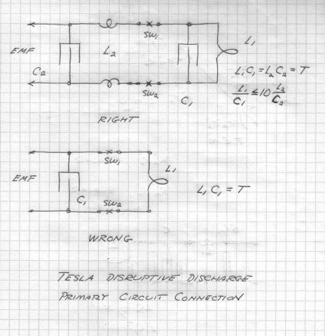
                            This arrangment could be altered so that the resonant plate supply is not rectified and is made to be the same frequency as the TMT. Ultimately i'm thinking to make the primary driver as given from Dollard:


                            The circuit I have shown is from the Colorado Springs Notes, read this for circuit values, these can be scaled. The reasoning here is that no resistance is wanted in the main tank circuit (L1,C1), it must be tight against leaks to assure maximum magnification factor. The Auxilary Circuit (L2,C2) is an impedance matching network to carry energy from the supply E.M.F. to the tank circuit M.M.F. The energy in L2 C2 refracts into L1 C1 so as not to disturb the primary M.M.F. This M.M.F. to be maximized to the highest possible magnitude.*

                            Another power supply is under consideration to supply oscillations, with either a 304TL or a 833A tube, which I now have a suitable filliment supply transformer now..

                            I'm very happy Eric Dollard now has over $22,000! This is awesome!
                            Last edited by Sputins; 02-12-2013, 01:24 AM. Reason: pic
                            "Doesn't matter how many times you kick the coyote in the head, it's still gonna eat chickens". - EPD

                            Comment


                            • Hey All,

                              Eric asked me if I could get him a copy of "Method of Symmetrical Co-Ordinates Applied to the Solution of Polyphase Networks" by Charles Fortescue. I found one on scribd but can't download it without paying for a membership. Can somebody that already has a scribd account download it and PM me with a link? Method of Symmetrical Co-Ordinates Applied to the Solution of Polyphase Networks-xSf

                              @lamare, Eric said that he is not consistently transmitting nor receiving on any particular frequency at the moment so trying to contact him via ham radio isn't feasible.

                              @lessismore, I see that you are viewing the thread. Eric speaks about you as the one who triggered is realization about the equal and opposite forces of the magnetic force vs the dielectric force on a T.E.M. line. He appreciates your help and wishes more of the technical kinds such as yourself would continue to give input into many of the topics presented.

                              Thank you to everybody that has donated to Eric and has spread the word about the Indiegogo Campain for Eric Dollard. He has finally been able to consistently eat right and not be stressed over not knowing where the money will come from to keep his car (home) in good running condition. A BIG THANK YOU TO TECHZOMBIE for all of your effort. Without you, Eric would still be scrounging for change.


                              Dave

                              Comment


                              • Awesome news about the fund raiser! Excellent PR work by techzombie.

                                Originally posted by Web000x View Post
                                Hey All,

                                Eric asked me if I could get him a copy of "Method of Symmetrical Co-Ordinates Applied to the Solution of Polyphase Networks" by Charles Fortescue. I found one on scribd but can't download it without paying for a membership. Can somebody that already has a scribd account download it and PM me with a link? Method of Symmetrical Co-Ordinates Applied to the Solution of Polyphase Networks-xSf
                                https://ece.uwaterloo.ca/~ccanizar/p.../Fortescue.pdf

                                From this page Power and Energy System Group | Electrical and Computer Engineering | University of Waterloo
                                Last edited by dR-Green; 02-12-2013, 06:01 AM.
                                http://www.teslascientific.com/

                                "Knowledge is cosmic. It does not evolve or unfold in man. Man unfolds to an awareness of it. He gradually discovers it." - Walter Russell

                                "Once men died for Truth, but now Truth dies at the hands of men." - Manly P. Hall

                                Comment

                                Working...
                                X