another call with Eric
After this weekend, Eric is up to a conference call. Is anyone here interested in getting on a live call with him?
Let me know time frames (in Pacific time zone) and days of the week that work best for you all and I'll see what I can do.
Announcement
Collapse
No announcement yet.
Eric Dollard
Collapse
This is a sticky topic.
X
X
-
Thanks that last letter has instructions on making an impedance matching transformer.
I was working on my pi filter and ended with a shunt coil and series condensator. That works good too.
Here you can calculate the vallues:
LC Impedance Matching Network Designer | SiversIMA
Leave a comment:
-
-
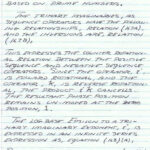
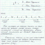
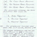
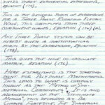
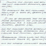
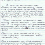
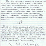
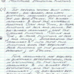
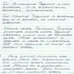
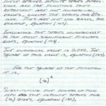
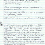
Dollard Letters, 6SN7/6080/etc exciters
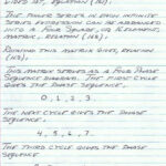
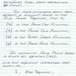
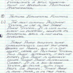
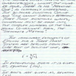
Here's a dropbox folder of letters from Eric.
The more recent ones have 6SN7/6080/etc tube exciter information.
Leave a comment:
-
Now and than I am thinking further on the Dollard/Tesla stuff and I remember I have read somewhere that it all comes down to what is happening inside a capacitor.
Now I am trying to get this more clear and your opinion on this. Is Eric saying that essential the energy transport from one plate to the other goes through counterspace and is not transversal electromagnetic?
The traditional view is that the Poynting vector fills the space between the plates but the Poynting vector is a transversal electromagnetic wave.
Eric said somewhere that we would have to do a measurement in the cap to know. I know that a lot of people tried that and they did find a circular magnetic field in a cap but the value was much smaller than calculated. No one has ever measured the predicted magnetic field. Only the shape is correct.
My opinion is that this magnetic field might be a small transversal component and that indeed the energy transports as a pulse through the electric fieldlines. Counterspace.
This article says the magnetic field is never measured inside a capacitor in 140 years. Other articles that measured with superconductive elements can only measure the dependence or shape of the field but not the real value, that value is always much lower than predicted.
http://www.antennex.com/shack/Apr07/dc_factfan.pdf
Is there some critic that can point me to an article where they did measure the magnetic field in accordance with Maxwells predictions? Also its value?
This overlooked detail of the magnetic field inside a cap might hold the falsification of traditional electromagnetics. How long will we ignore it as a measuring error?
Leave a comment:
-
good show
Nice builds there David. Good to see that you and a few others are still dedicated to the work. I'm looking at a crystal radio replication myself at the moment and looking forward to getting onto it. I have finished building my other transformer and electric magnet that I have been working on for some time now. Hope all goes well with you all,
Hope to hear more from you and Eric,
My best wishes,
Adam
Leave a comment:
-
Eric's forum
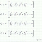
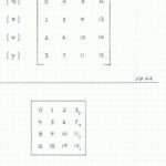
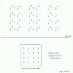
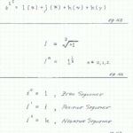
The only way for Eric to read the forum is if he is with someone that has a computer, since he does not own one himself.Originally posted by David G Dawson View PostIf this is Mr Eric P Dollard's Official Forum then it would be really nice if he were to turn up here at least monthly with some kind of report that let's us know what he is doing.
Or at least give it to Aaron or John just to Post here so we can all keep in touch - Thank you!
Aaron, thankyou for posting all of Eric's Math but the interest there would be for about 1% of the participants.
In reality, the Math should really follow something working at the bench and we have put the cart before the horse.
Lack of interest is shown by lack of progressive reports coming from all of his earlier followers.
It will probably be months before I see Eric but John Polakowski may see him in the near future and may be able to have Eric read the forum and post something.
Leave a comment:
-
Valve Amplifiers Morgan Jones
For those interested in Vacuum Tubes and also Amplifiers, this is the reference book made by Steven Mark on the interaction with the Earth's magnetic field when the power to the filaments is first turned on:
http://milas.spb.ru/~kmg/files/liter...rd_Edition.pdf
We are seeking that same 'kick' by creating a symphony of 3 various frequencies into 3 coils and the sole reason for my Tube Drivers.
Perhaps Bach had something to do with all of this.
This same 'kick' comes in a different form when you are standing in front of a large high power transmitter and you hit the 'ON' button, what you get is a 'Thung' and you feel it coming in through your head, through the body and down to your feet.
You always heard the noise but the sensitive ones would also feel it in the body as well.
Smokey
Leave a comment:
-
Picture Size
My apologies for the first two pics as they were taken with a different Camera and have tried twice to rectify but does not want to change.
Smokey
Leave a comment:
-
The Eric P Dollard Forum
If this is Mr Eric P Dollard's Official Forum then it would be really nice if he were to turn up here at least monthly with some kind of report that let's us know what he is doing.
Or at least give it to Aaron or John just to Post here so we can all keep in touch - Thank you!
Aaron, thankyou for posting all of Eric's Math but the interest there would be for about 1% of the participants.
In reality, the Math should really follow something working at the bench and we have put the cart before the horse.
Lack of interest is shown by lack of progressive reports coming from all of his earlier followers.
What we most dearly seek is a device that clearly demonstrates 'Energy Synthesis' and something practical and physical that we can all build and put to work in our own homes.
This was one of the initial attractions of Mr. Dollard in that he may be able to help in that particular area.
As a consequence I have continued with my experiments and am currently putting together Vacuum Tube devices that will allow me to drive the coils of the Steven Mark TPU (Toroidal Power Unit).
There is an actual replication of the TPU from Otto (now deceased) and Roberto and their pdf is here:
http://oriharu.net/otto_ronette_TPU_ECD-V1_0.pdf
I have done most of the Don Smith/Kapanadze/Tesla/Dollard and similar style of builds and probably all I achieved was a deeper understanding of what was actually required and why I have finally chosen the Steven Mark TPU.
The Mark TPU is what I call an expansive TPU or ETPU but what I am also building as a dual set, is the contractive TPU or CTPU.
I am stupid enough at the age of 72 to realise that there will always be two ways 'to skin the cat'.
This follows on from the 1966 RCA CTC-5 colour TV implosion in Chicago where a young Negro boy was killed by nails in a screw shape form (everything metallic) being propelled violently into the screen of the TV and heading for the area of the Neck Ferrite and its associated horizontal and vertical deflection coils (similar stories from Matsu****a).
This is the base where Steven Mark began but for some reason unknown, followed the opposite course in an expansive device, the ETPU.
Why he did not follow the contractive or implosive line of reasoning from the initial event, only he will know.
I am repeating what I have posted earlier.
What I have built firstly is a replication of the CTC-5 power supply using 5U4Gs (5X4G, 5AS4, 5T4, 5Z3) as this is where it is believed the cause phenomena may have initially begun with an ac ripple on top of the DC HT which is at 380 volt and also lowered by resistance to 300 volts.
There are two dual rectifiers 5U4Gs working together here and to quote RCA, 'in case one failed' was the sole reason for the two.
As always with replications of vintage Radio it is not easy to acquire the parts required and had to settle for the transformer out of a Tek 583 Oscilloscope and will have to use a Variac here as filament volts is only 6.3v and the 5U4Gs use 5.
Failure modes need now to be applied to this power supply to see what will manifest with respect to an ac ripple on the DC HT.
Learning how to parallel transformers has led me along this path and being severely ostracised in the process by others 'still in the box' and is worthy of investigation as it leads to most interesting conclusions.
What would be of interest here is that one of the 5U4Gs drifted off in a weakness with respect the other and set up a distinctly different oscillation in the secondary windings of the transformer and this anomaly was presented to the workings of the TV with an implosion resulting - just conjecture on my behalf at this point.


Two other builds are also required and this is for a dual set of four 6BQ7A Drivers for the 3 control coils with the second set now being built.
This is believed to be the Tube that Steven Mark initially used to drive his coils.
As you already know that I am a follower of Vacuum Tubes for many reasons and one is the fact that a Tube is capable of producing the even and odd harmonics where I believe these are lost in solid state which is also prone to noise and requires excessive feedback to overcome with consequent excessive distortion.


This is where I would like Eric to come in and advise if we are on the right track or not as his Tube knowledge would be invaluable here.
I have two 1950s style TV Waveform Generators I am using as Signal Generators (Philips GM2891 and a Taylor 94B) and for these as Drivers/Amplifiers have built Eric's 6SN7 Driver as a pair as the Wave Gens are only outputting about 30mV.
Beauty of these units is that they are capable of switching the output into either one or other or both of the horizontal and vertical deflection coils
which may assist in the development of the 'Energy Synthesis' frequencies and voltages required.
They cover a range from 4 to 220 Mhz but may need to be able to reduce this down into the Khz ranges and this is my only remaining modification required.

What this method of aluminium rail building is doing is an attempt to show how it can be done simply and in this picture the two extra Valve bases just show how many can be fitted onto the one 6" rail as 6SN7GT Power Drivers.
I am attempting to show newcomers that Tube builds can be made reasonably simple using this means of construction.

What they do here in the Master Oscillator is begin at the 31 to 250Khz frequency for a 625 Line system and divide down, 6,250khz, 1250 hertz, 250 hertz, 60 hertz and this uses different style dividers and step counters.
What is of note here is the use of a Plate to Grid multivibrator feedback system in the 1st Divider which is a little 'out of the box'.
All I need do here is extract the khz signal from the Master Oscillator or any of these dividers for an external use and amplify.
My requirement was simple in that the Drivers needed to be driven by Tubes and not solid state for the reasons stated above as well as the phenomena of a vacuum and only people like Trevor James Constable realised the consequences of the vacuum.
These units have 13 and 23 Tubes respectively and have a preponderance of ECL80/6AB8 and 12AT7/12AX7/12AU7s so well liked by the audiophiles.
Both these units are now up and working and were a delight to restore and good to see the glow of all the filaments again.
I wouldn't have enjoyed the restoration unless there were some reason to be able to use these units for actual use at the bench.
I spent two years working with solid state Drivers and came away most dis-satisfied with the end product and the reason why I now choose Vacuum Tubes to do this particular function.
Once a result is achieved with the Tubes will I bother looking at a solid state option.
What we also have are the AD-YU Delay Lines in 3 different pair sets and this is always a consideration of driving coils in being able to modify the times that all 3 frequencies meet in the coil mix.
The AD-YU arrived without knobs and required a dual set as one turns inside the other and this problem has now been overcome.
Have only recently tested the range of this device and find it covers from 0 to 24.21 Henry in 36 steps and not the original 12 as initially observed - one coil set with 3 capacitors each to select and has a variable control for each range selected as well.
See this as being a means of achieving the 'kicks' required to open the door to an ambient energy.
It is where you hit the other frequencies on which part of the wave is the required criteria here and I have covered this earlier with my 'multiply and divide' explanation.
The TPU is no different to Tesla's Magnifying Transmitter (TMT) but uses 3 coils and is expected to go into a multiple concatenated state that amplifies but will rely solely on how it is driven.
See pictures on Page 48 of this Forum for the Delay Lines.
At this time I am not really interested in what others say or are doing as I have been at this now for some 12 years at the bench and am now going my own way and eliminating all of the distractions.
It has only taken me some 72 years to learn how to stick my finger up!
I have still seen absolutely nothing out of this year's conference that I am able to use so was a total loss to anybody outside of the USA.
Have just recorded the latest audio from Eric/Aaron and will view that later.
Later: Found it almost impossible to concentrate on due to the distorted voices and fade in and out and finally left it in preference for other work.
Simply prefer a Q & A in a black & white format and I thought that was what the Forum would be used for.
Later again: I felt guilty and went back and listened a little more to the audio tape but again, had other things to do.
Sorry!
I will put up pictures of the two TV Wave Generators and also suitable Tube power supplies if any interest is shown.
What I present here may look rather complex but is only a means to an end to have all the available equipment to do the initial experimentation or as Eric would put it, 'the electrical experimenter' as it is all needed to gain results where a much simplified unit would be made available after conclusion of experiments which anyone could build.
At least that is the main goal.
The other pdf that may be of interest on the TPU is the initial one between Lindsay Maddix and Steven Mark and explains the base concepts derived from the imploding RCA TV and is available from Scribd ('Stephen Mark's Toroidal Power Unit').
Smokey
Leave a comment:
-
-
Greetings all. It's been a while since I've posted. Spent the last 3 weeks in France, Switzerland and Italy living in a tent and just got back on Sunday evening so (practical) things had been on hold for a few weeks while I was making preparations and what not. Unfortunately I couldn't make it to the latest conference call because I think I was walking around Venice at the time, but thank you for the message Aaron. I'm sure I would have enjoyed it more than the human infested circus I was in! Also thanks for posting the new material. Normal service on my end should be resumed as soon as possible
Leave a comment:





Leave a comment: