Eric Dollard - more photos, etc.
Last 3 posts and photo albums we just posted:
Trip to the Conference from Lone Pine California to Spokane Washington | Eric P. Dollard – Official Homepage
Lone Pine California | Eric P. Dollard – Official Homepage
The Fate of the Camp David Installation in Bolinas California | Eric P. Dollard – Official Homepage
Announcement
Collapse
No announcement yet.
Eric Dollard
Collapse
This is a sticky topic.
X
X
-
Landers Facility by Eric Dollard
The Landers Facility of Eric Dollard and Walter Deroche | Eric P. Dollard – Official Homepage
New blog post by Eric on the Lander's Facility - check it out!
Leave a comment:
-
Sterophonic telluric antenna
Transmission System Structure A52-W – Beginning of the Project | Eric P. Dollard – Official Homepage
That is the last photo album for the day - shows the other location for the telluric project so it will be sterophonic, which gives the ability to help locate the source of seismic activity or other generated signals.
Leave a comment:
-
Answers to Important Questions
DO NOT! use PVC for High Voltage RF insulation, nylon is even worse. Lexan or plexiglass is even better. Teflon is good electrically, but usually too mechanically weak. It is possible to make a Tesla Transformer operational in the VLF band around 30 kilocycles per second. This involves involves the use of a small power distribution transformer such as the variety up on the utility pole feeding your house. The version with two primary bushings is a half wave coil in self-resonance mode and thus would act like the Cosmic Induction Generator. The single bushing variety such as used in multiple grounded neutral systems are quarter wave coils and will work as a Tesla Transformer. The elevated capacity will go to the high voltage bushing and the telluric connection will be to the high voltage neutral. Discussion of transformer resonances were given here: http://www.energeticforum.com/eric-d...tml#post199540
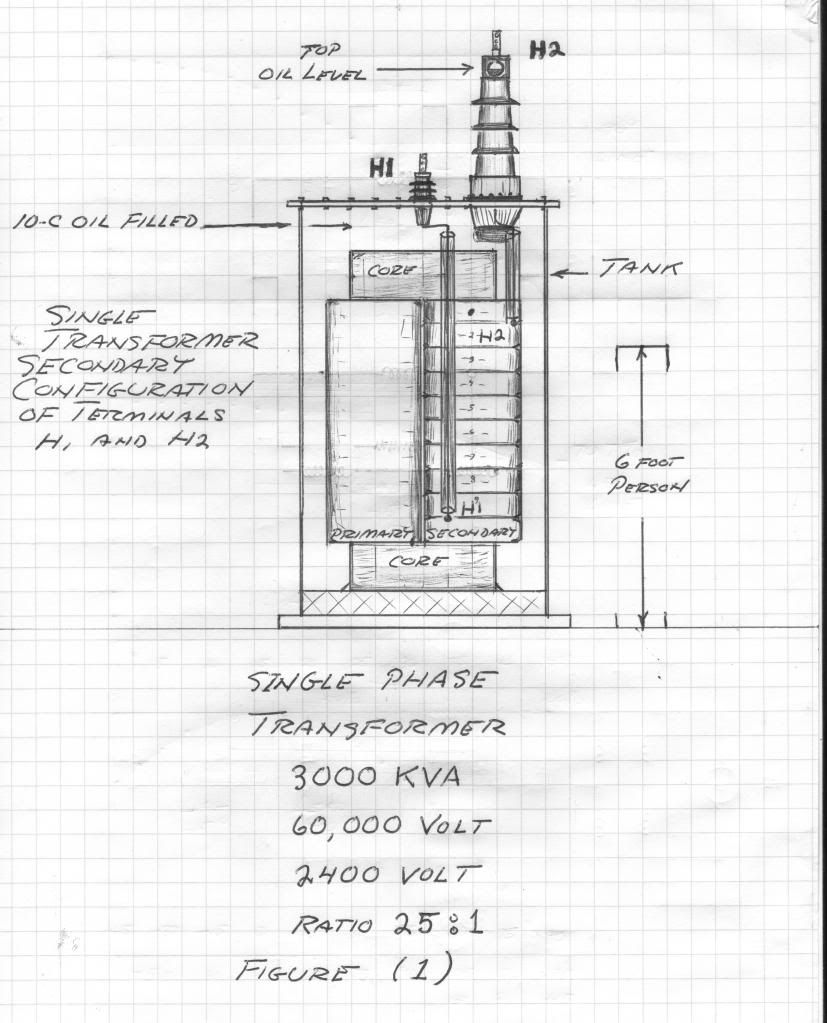
http://www.energeticforum.com/eric-d...tml#post199969
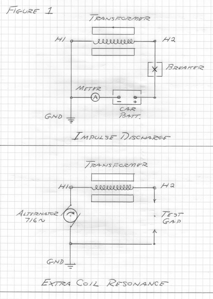
The transformer shown is a quarter wave coil variety obviously much larger than a distribution transformer, but then its resonant frequency is only 716 cycles per second. This makes it an Extremely Low Frequency Tesla Transformer.Last edited by t-rex; 06-23-2014, 03:41 AM.
Leave a comment:
-
Eric Dollard Update and Photo Albums
Here are the most recent photo albums we just uploaded today to Eric's homepage - most pics relate to the Advanced Seismic Warning System - read his description on each post to see what the pictures are about - please share on twitter, facebook, google+, etc... when you're on each page to help get the word out:
Bell Telephone Switching Systems and Related Carrier Facilities | Eric P. Dollard – Official Homepage
Bell Telephone Outside Plant TD2 Microwave Antenae | Eric P. Dollard – Official Homepage
Primary Toll & Autovon Switching Center Joint Bell Telephone & USAF North American Air Defense Installation Nucelar Attack Resistant | Eric P. Dollard – Official Homepage
Historic DBR Carrier Telephone Line | Eric P. Dollard – Official Homepage
DBR Line Main Repeater Office | Eric P. Dollard – Official Homepage
Transmission System Structure A52-E | Eric P. Dollard – Official Homepage
Transmission System Structure A52-E – Beginning of the Project | Eric P. Dollard – Official Homepage
You can see that Eric and Justin have been extremely busy out in the hot and windy desert getting the poles and that shack in proper order. And having to dig some holes in the rock hard ground makes it even more difficult but they got it done! The remaining poles are in good shape, the loose and dangling wires have been taken down or put back where they belong and the shack is rebuilt - doesn't look like it but the paint actually matches the natural wood look so it still looks unfinished but is not.
We were not able to give a lot of updates during this process because Eric and Justin were working nonstop for a whole month without reliable internet access for me to get the pictures and show you all what has been going on, but now you can see the Advanced Seismic Warning System has been moving full steam ahead for a while now.
So Phase 1 of the "Long Lines Project" is complete. The two facilities that have been granted to EPD Labs had been rendered stable and safe. Phase 2 coming up in the fall season cooler weather will be glomming the material to put up on the pole, another massive effort! You can see that some of that wire has already been acquired by their efforts in some of the pics. Phase 3 in the spring will be putting the glommed material up on the poles at the facilities. Phase 4 in the following fall will be making the connections to terminal equipment to begin the telluric signal reception process. After that has yet to be determined but this is the overall plan that they been carrying out.
p.s. Yesterday, Steve (director of EPD Labs) came here to pick up about 2000 pounds of GLOM from my friend Mark McKay who graciously donated some EXTREMELY VALUABLE equipment and parts - transformers, scopes, capacitors, tuning coils, you name it! Mark is the one who posts as Spokane1 in the Gray Tube Replication thread and he duplicated the Borderlands Tesla Transformer experiments that you probably saw pictures of from last year's conference. Aaron
more to come...
Leave a comment:
-
Eric Dollard update
I'm with Eric right now uploading a bunch of photos to his website at Eric P. Dollard – Official Homepage | The only man who has replicated Tesla's wireless transmission technology. - the Bell Telephone photo galleries are related to the Advanced Seismic Warning System. We're working on uploading the next photo album, which will show the right-of-way that we have for the telluric project with the telephone poles. We'll start with what they looked like before the repair job by Eric Dollard and Justin Miller (secretary/treasurer of EPD Labs). Most were in good shape but some needed some serious work. We hope you like the photos - stay tuned for more to come.
Eric is also here working on his presentation for the conference - yesterday, I helped him put together a 231 slide powerpoint presentation for the conference and we're not even done!
If we have time, we'll try to do a Q & A session, interview(s), etc... but that will probably have to wait until after the conference.
p.s. Yesterday, Steve (director of EPD Labs) came here to pick up about 2000 pounds of GLOM from my friend Mark McKay who graciously donated some EXTREMELY VALUABLE equipment and parts - transformers, scopes, capacitors, tuning coils, you name it! Mark is the one who posts as Spokane1 in the Gray Tube Replication thread and he duplicated the Borderlands Tesla Transformer experiments that you probably saw pictures of from last year's conference.
Leave a comment:
-
I have read this article and if I understand it well it argues to replace the laws of field induction with laws that relate fields to currents, changing currents and charge.Originally posted by mikrovolt View PostThe general term "Displacement current" was derived as a mechanical analogy by observation.
Ambiguity does exist.
http://www.antennex.com/shack/Apr07/dc_factfan.pdf
But if you have a normal transformer with iron core. The magnetic field in the primary equals the magnetic field in the secondary but it exists almost entirely in the iron core. So to cause a secondary current this magnetic field has to induce an electric field that causes the current. I don't see how you could get rid of this induction of fields idea in this particular case. If the secondary magnetic field would be inside the secondary windings than ok but not if the field is entirely in the iron.
So I still hold on to the induction of fields idea but interesting article and thoughts!
Leave a comment:
-
In my opinion Eric's homepage should also include the original experimental video's like this one:
Tesla's Longitudinal Electricity - Eric Dollard, Peter Lindemann & Tom Brown - YouTube
Free Videos | Eric P. Dollard – Official Homepage
They are the ones that still inspire the most. The other video's are attempts to explain this.
Just a note
Leave a comment:
-
Very nice! I'm not sure that a loading coil specifically is necessary. As far as I can make out the main reason Eric used it in the video was basically to bias the transmitter a bit, to sink the energy in the direction rather than towards the free terminal. I think a bucket of soil and such in parallel does a similar job, just something to load it a bit. But you may find that the bulb gets less bright that way because it gets loaded a bit too much. But on the plus side you might then be able to light bulbs from metal plates near the bucket!Originally posted by Sputins View PostThe bulb lights of course, however Iím yet to experiment with a Ďloading coilí as to whether it improves the output from the bulb or not. Yes, there is a subtle Ďfieldí emanating from the bulb, but yet to try and charge a capacitor etc. You can feel it (very subtlety) on you hand. It feels like gentle little prickles near the glass of the bulb.
Leave a comment:
-
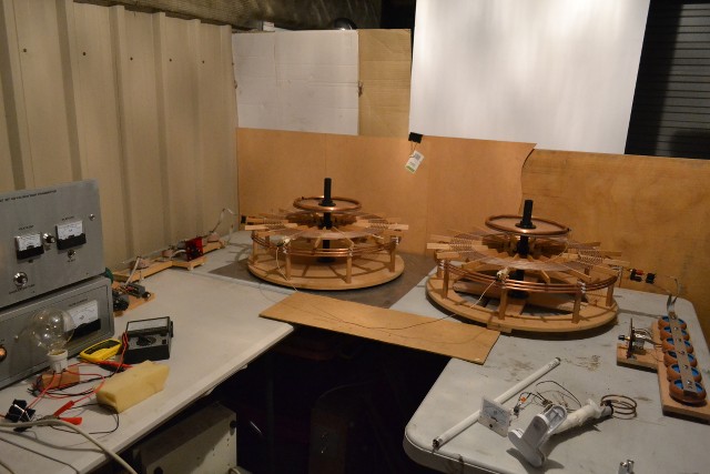
General setup. Left hand side coil set is the original, which is powered by the transmitter. The Right hand side coil set is the new one, which is setup as the receiver at the moment. One wire connects the two telluric outputs together. The receiver coil does light plasma tubes from the terminal capacity, could be optimised further I think.
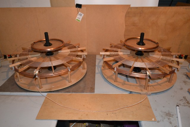
The twin, (image) coil-set is born. Secondaries are wound opposite to each other. The primary coils are both wound in the same direction. (Later they can both be connected in series).
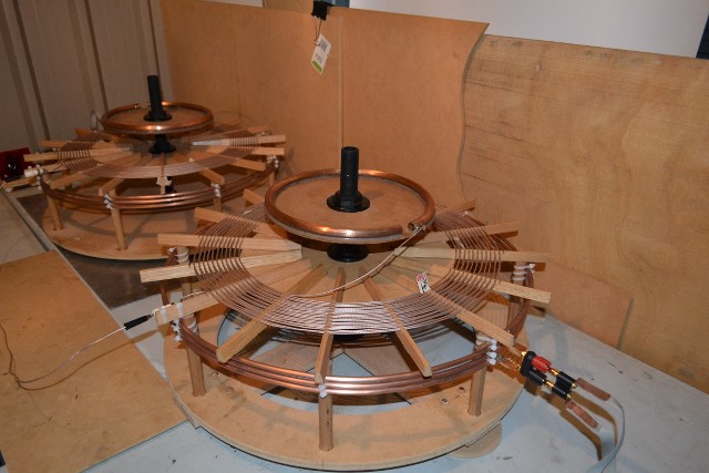
Extra coils omitted for the time being.
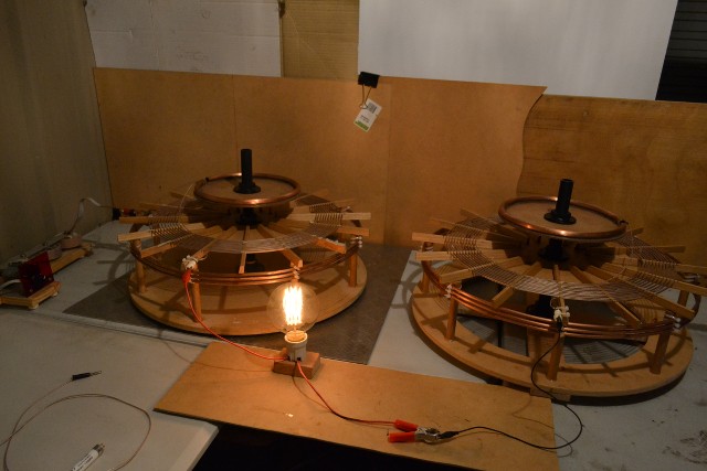
The bulb lights of course, however Iím yet to experiment with a Ďloading coilí as to whether it improves the output from the bulb or not. Yes, there is a subtle Ďfieldí emanating from the bulb, but yet to try and charge a capacitor etc. You can feel it (very subtlety) on you hand. It feels like gentle little prickles near the glass of the bulb.
More later.
Leave a comment:
-
I am sorry about the mistake let me clarify:
In order to use an inexpensive signal source I would build a series tank like the video.
Which is simply capacitor followed by coil for air coupling. If you use an HF rig then you already have a nice sine wave and enough power and this step is not necessary. You can still use tube amplifier. The effects will be good the 2N5109 follower should give enough amplification about a watt at this stage.
here is generic vacuum tube example EICO-324-Signal-Generator.pdf
https://www.youtube.com/watch?v=fUo6IhSouEI
Letís plug in some numbers from the video and check our results to make sure we are doing correctly, then we can modify the capacitor for 3.17 Mhz.
11.5 uH and 182 pF LC Resonance Frequency Calculator - Ekswai
you should get 3.48 Mhz however the impedance is about 1000 ohms Z
for 3.17 Mhz coupling at 300 ohm Impedance the values are about 15 uH and 168pF.
If you want to build your own capacitor, Tesla would try the FR4 dielectric.
It should not cause fumes at 1 watt.
Parallel Plate Capacitor Capacitance Calculator
I think what is important in replicating is the product or resultant be identical.
The square waves are not a good idea because they will cause wide band splatter. Yes old scientist got it to work so now we know, so letís be responsible and set a good example and be a good neighbor by keeping this narrow band. my latest experimental driver uses almost the same compression as the single element Pi is based on a Garbor wave function which is analog.Last edited by mikrovolt; 06-18-2014, 08:41 PM.
Leave a comment:
-
@Mikrovolt Ė Thanks for the links concerning pi-networks and displacement current. Iíve used that displacement current term only because Eric used it in the SBARC video demonstration. Whether it is accurate or not Idk? - Also the spiral coil in the video is a twenty turn coil (two times ten turns, each turn is actually two turns, one on top of the other). The inductance per turn canít be deduced simply by dividing by 20 as every-other turn is of a different length. (Spiral). However the overall inductance of each spiral coil I measure to be ~270uH.
@dR-Green Ė Yes, were all (you know who you are) doing our own independent work based from of the same teachers. (Tesla & Dollard). As a big picture it is really a collective collaboration, many of these things havenít been seen before and itís really amazing. It shows that Tesla was right when he said ďthe future is mineĒ!
@Orgonaut - Tesla did utilise the conical shaped coil as seen in a photo. Which I suppose seems to be a combination of a flat spiral and a cylindrical shape sort of form factor. He must have had his reasons for this?
@ All - The second half of my receiver coil set is completed and to my delight it tunes to the same resonant frequency or at least within the same resonant frequency bandwidth. Fine decimal point tuning is yet to be determined. This is for the primary tank and secondary spiral coils only (to un-complicate matters). Certainly connecting up the two telluric outputs activates the receiver coil set to become energised and the terminal capacity will light common plasma tubes and draw off small arcs. Optimising the receiversí primary tank circuit for powering loads is another thing to yet achieve, along with re-fitting the Extra coils and tuning to 1860Kc. Also there are the various setup configurations to play with like the CIG format of course.
Other observations:
Iíve not felt any cooling effects from the coils as yet however it is only 6 degrees Celsius at night here, so Iím damn cold anyway. I tend to feel warmth though. When the coil is off-tune and the driving frequency being slightly lower than the Ro (ω) of the coil, when bringing your hand near the top terminal capacity and holding it there, in order to bring the coil back into resonance again, there is quite a tingling and warmth felt on the hand right at that point. Even if itís at a reasonable distance away.
However for me, with low to medium power, Iíve found holding onto the telluric output has the greatest biological effects. You feel nothing as far as an electric shock-like sensation, but holding on to it for a few minutes one does feel (pardon the pun), somewhat energised. You can actually feel your body gradually reacting, not an unpleasant feeling, but actually a really pleasant one! (Difficult to describe), it sweeps through your body, like itís charging up your bodyís cells or something? I donít think Iím imagining this at all. Further inquiry is needed here to establish what the effects actually are, whether imagined, healthy or harmful? (So far it's been healthy)!
Pictures & video later.
Leave a comment:
-
I realised that the globe or the vaccuum tube in the middel of the pancake is used to focus the Tesla current
Leave a comment:
-
One more idea I had. I think I am starting to understand the Tesla coil so I will post my understanding so anyone can correct that. Also I will post an idea.
Eric explains that the Tesla coil is build as a transmission line. The transmission line is, when in quarter wave resonance, a monopolar situation. Meaning that the field is maximal and minimal but not at the same time. Thereby it is radiating to the environment instead of closing in a circuit.
Now the Tesla coil is basically a transmission line reversed. Meaning the capacitors are in series and the inductors are parallel. Eric demonstrated that in this situation a quarter wave resonance leads to the magnetic field and the electric field being in fase at the same place. I know to calculate this is nearly impossible and requires solving fourth order differential equations as Bewley produced these equations. Eric produced solutions to these equations basically using quarternions from Maxwell but even that in a simplified engineering way like Steinmetz did with second order equations.
So we have a Tesla coil with the unique features that the electric and magnetic fields are maximal in fase and on the top.
Now my idea. If we would construct the Tesla coil in a hyperbolic way like a hyperbolic antenna would that not focus this field? Could we produce a Tesla beam? The coil would be a combination of a flat pancake coil and a Colorado springs coil I guess.
Or perhaps the flat pancake coil is already a way to focus the beam? I don't understand that yet.Last edited by orgonaut314; 06-17-2014, 11:55 AM.
Leave a comment:
-
Very well said everyone! I would like to contribute as much as I can. Some of my observations are speculative but one is that every time I put on my coil I come to think 'he where is that cold coming from?'. Again and again. Just like the occasionally bird that keeps trying to fly in my room. Also it has a more than remarkable influence on my health. I get very very clear and quiet. Is that an effect on my consciousness? It makes me think brighter. But hey we can't rule out the placebo but it is a damned good placebo so give me more
What also struck me on an internet search and when I found it computers started to reboot etc etc so I was on a trail because negativity was working against me but it was the name Hutchison. You might know about him. He experimented with two Tesla coils and high voltage dc and a tube driver and produced some remarkable video's. He admits that he is not able to reproduce them so strong anymore since 1990. He also admits not knowing how it works and viewers have to spend hours watching just to see something. There is also an effect that background radiation seems to drop. So now he is in Japan working with the radiation problems there.
Hutchison than in the 80's at 4 minutes levitation etc.
hutchison effect - YouTube
Hutchison more recent.
Dr. Thursten visits Hutchison Lab - YouTube
Fusion of wood and metals.
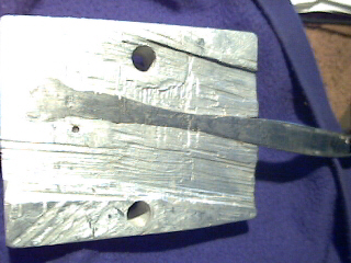
His lab
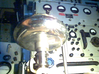
His setup
http://www.hutchisoneffect.ca/Resear...JAug201997.pdfLast edited by orgonaut314; 06-17-2014, 09:02 AM.
Leave a comment:
Leave a comment: