Announcement

Collapse
No announcement yet.

Eric Dollard

Collapse
This is a sticky topic.
X
X
 
  • Filter
  • Time
  • Show
Clear All
new posts


  • Very few are tooled up with Vacuum Tube technology and you don't get to see plasma with solid-state.
    What resides below the Aether - plasma.

    Smokey
    I designed/built a small TC with a solid state driver- works just fine. Produces plasma too! It has various feedback and modulation improvements that you won't find on a garden variety TC, all withing a small package. To do the same with tube-tech would fill half the workbench.
    Tubes are fine for some very high power applications, but since we have better technology for most things, why not use it?

    BTW, if you want a good book on the subject of plasma production and properties:

    "Ionized gasses" by A. Von Engel, published by the American Institute of Physics.

    Comment


    • Originally posted by dR-Green View Post
      I don't think it's that simple. I've tested two different extra coils on this basis, that is adjusting the wire length in order to end up at a particular frequency. Unfortunately it has no meaning, at least on such a simplistic level. My conclusion is that an extra coil of any random wire length will work with any random secondary if thinking this way about it, and you'll end up with some "random" frequency that relates to the secondary and extra coil as one length of wire, no magic, no different than using "matched" coils under the illusion of using 1.57 times wire length, there is no real matching at all. Also you would have to assume 157% extra coil propagation velocity in order to make the theory work that far, maximum I've achieved so far is 130%.

      I think what Eric had in mind was concatenated resonance where the frequency of each coil is the same alone and connected in series; 1/4 + 1/4 = 1/4, not 1/2 frequency (approx) as above, it was and still is experimental. The way Tesla did it in CS was with the extra coil as a series inductor so the secondary frequency was raised by the extra coil. That requires an extra coil of a particular inductance, not frequency or wire length.
      Very true. In Tesla's Colorado springs notes, he used wire length on his calculations only to find that the frequency was lower than expected. This is due to the inductance and slower velocity factor.

      Use the inductance formulae found in engineering text or the ARRL handbook and you will be very close to the desired resonance.

      I don't understand all of this "golden section" mysticism that is being introduced into the coil design. Eric Dollard got two resonant peaks on his demo due to the way the coil was wound. In the end, he still had serious attenuation, since he could not light any bulbs on the beach! All he proved was that it was a viable EM setup. No scalar, no lossless power transfer.

      IMO,The Tesla system had more to do with electrostatics and VLF than any of this other stuff. Read the notes and patents and you will see what I mean.

      Comment


      • Originally posted by jimm View Post
        Very true. In Tesla's Colorado springs notes, he used wire length on his calculations only to find that the frequency was lower than expected. This is due to the inductance and slower velocity factor.

        Use the inductance formulae found in engineering text or the ARRL handbook and you will be very close to the desired resonance.
        The frequency of what was lower than expected? Tesla's extra coil measurements show 123% luminal propagation velocity. Taking this 123% as an example, what I was referring to was using 1.23 times the wire length to bring the frequency back to the original intended value. The wire is made 1.23 times longer because propagation is 123% the speed of light. If F = 1000 kc then by using the engineering textbooks you will have a measured frequency of 1230 kc. Extend the wire length to 1.23 times what the textbook says and you are back to 1000 kc.

        Originally posted by jimm View Post
        In the end, he still had serious attenuation, since he could not light any bulbs on the beach! All he proved was that it was a viable EM setup. No scalar, no lossless power transfer.
        I didn't get the impression that he was trying to light any bulbs on the beach. It was a different setup. It was a transmission of an audio signal through the earth as a demonstration of Tesla's principle, ham radio style (legal and non-interfering). By the way scalar is a dirty word here.
        http://www.teslascientific.com/

        "Knowledge is cosmic. It does not evolve or unfold in man. Man unfolds to an awareness of it. He gradually discovers it." - Walter Russell

        "Once men died for Truth, but now Truth dies at the hands of men." - Manly P. Hall

        Comment


        • Tesla notes

          Dr. Green,

          Thank you for responding.
          The CS notes has various references to the length being less than lamda/4 but the first one I came to on a quick look was on page 72 at the bottom of the page. As far as know, the oscillator was more or less pure EM, but the difference was in the "antenna".
          I also remember reading his account of a low power test of Wardenclyfe where he calculated the pulse return time around the circumference of the earth using the standard speed of light.

          I have not seen any evidence of the FTL aspect in my TC. It follows the
          1/(2*pi*sqrt(LC)) in my lab fairly close. Any differences can be attributed to geometry and distributed capacitance.
          Distributed capacitance in the coil is what results in it's "natural resonance".

          Could you share more details on your setup and test methods?
          I'm intrigued...

          E.D's demo on the beach was just the reception of an RF carrier. The tone was produced by the radio's BFO. It's just a radio hooked up to a novel tuned antenna, nothing special. At that distance a coil of wire and a ground would have had the same result.
          I wanted to see a demo of the much touted "lossless" power transmission.

          In ham radio, when propagation is favorable, there have been reports of accidental contacts hundreds of miles away, while the transmitter was under test on a dummy load. ( a resistive element that dissipates power in heat for testing and is not supposed to radiate) . Sometimes it doesn't take much...

          Comment


          • Originally posted by kostja View Post
            ... p.s. it's Tesla's Birthday today
            Well it will be on the 10th.

            Born 10 July 1856, Smiljan, Austrian Empire (modern-day Croatia)
            Died 7 January 1943 (aged 86), New York City, New York, USA

            Happy Birthday Nicola

            Comment


            • Notes on Cosmic Ray Detector

              1. For small capacitance like 10 pico-farad the potential required to trigger tube will be kilovolts. The particles of radiant matter will be but a small fraction of a picofarad, but have a very high potential.

              2. The shape of the curve for trigger voltage vs capacitance is very important for study.

              3. The phototube may work better outdoors for certain experiments.

              4. The Western Electric 313-C is similar to 0A4-G
              SUPPORT ERIC DOLLARD'S WORK AT EPD LABORATORIES, INC.

              Purchase Eric Dollard's Books & Videos: Eric Dollard Books & Videos
              Donate by Paypal: Donate to EPD Laboratories

              Comment


              • Originally posted by jimm View Post
                Dr. Green,

                Thank you for responding.
                The CS notes has various references to the length being less than lamda/4 but the first one I came to on a quick look was on page 72 at the bottom of the page. As far as know, the oscillator was more or less pure EM, but the difference was in the "antenna".
                I also remember reading his account of a low power test of Wardenclyfe where he calculated the pulse return time around the circumference of the earth using the standard speed of light.

                I have not seen any evidence of the FTL aspect in my TC. It follows the
                1/(2*pi*sqrt(LC)) in my lab fairly close. Any differences can be attributed to geometry and distributed capacitance.
                Distributed capacitance in the coil is what results in it's "natural resonance".
                The secondary is the Telluric transformer and it will work with or without an extra coil. With a vertical wire or a small terminal capacitance the energy radiates into space like a normal transmitter, but with a large capacitance the energy is contained and reflected back into the coil, into the earth, and back into the coil and so on. It doesn't need the extra coil.

                How did you test your coil? Geometry does play a role which is one of the things that must be considered, but capacitance calculation is based on geometry alone and doesn't consider wire length which is the thing in question here. Propagation velocity is measured in terms of (supposed) distance travelled I.E. wire length.

                (Extra coil) Diameter = 8.28cm
                Height = 8.28cm
                93.25 Turns
                Conductor Length = 24.256 Metres

                Luminal Wavelength:
                = 4*24.256
                = 97.024 Metres

                Luminal Frequency:
                = Velocity Of Light/Luminal Wavelength
                = 299792458/97.024

                = 3089879 cycles/sec

                Measured Frequency:
                Direct = 3676700 cycles/sec
                10pF = 3990500 cycles/sec

                Originally posted by jimm View Post
                Could you share more details on your setup and test methods?
                I'm intrigued...


                Originally posted by jimm View Post
                E.D's demo on the beach was just the reception of an RF carrier. The tone was produced by the radio's BFO. It's just a radio hooked up to a novel tuned antenna, nothing special. At that distance a coil of wire and a ground would have had the same result.
                I wanted to see a demo of the much touted "lossless" power transmission.
                You seem to understand how the signal was produced/transmitted, so what did you expect to be done differently in that respect? The coil is the same however you choose to power it. An unmodulated carrier is the transmission of power. I can't say what was done 15 years ago but I've sure seen enough in my own experiments through the fact that the amount of power received varies depending on the distance between the transmitter and receiver earth terminals. The coils remain in the same place the whole time, distance between the "antennas" makes no difference.

                People working with this stuff must experience a lot of "accidents" that conveniently allow everything to work every time they turn it on that's all I can say
                http://www.teslascientific.com/

                "Knowledge is cosmic. It does not evolve or unfold in man. Man unfolds to an awareness of it. He gradually discovers it." - Walter Russell

                "Once men died for Truth, but now Truth dies at the hands of men." - Manly P. Hall

                Comment


                • Thinking out loud

                  I'm wondering about tertiary location, the earths capacitance and magnetic fields along with the solar location will have an effect. It may be small it may be enough to cause some adjustments to be made.

                  If everyone picked a singular frequency to work with and then reported the results along with the XYZ & t coordinates (t=time & date) then more progress could be made. Personally I found the higher frequency easier to build and test then a large 1 kilo cycle rig.

                  were dealing with the electrostatic field once the magnetic field is rotated. electrostatics is a field unto it's own. It may prove to be very difficult to build a rig to work on a small scale, Tesla was not working on small but large enormous amounts of power transportation. scale is indeed a factor here. that doesn't mean size scale but power scale.

                  Comment


                  • experiments

                    Dr. Green,

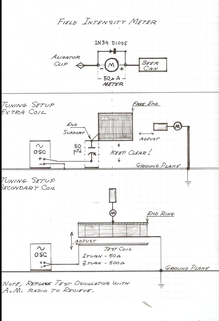
                    It's great to have diagrams to accompany an explanation!
                    It all looked pretty good for a basic test setup. The weakest link is the generator used. The diagram does not indicate a frequency counter, so I assume that your measurements relied solely on the dial calibration of the signal generator? It could be off...

                    I have used similar methods, but also use square wave "ringing" tests with resistive coupling rather than capacitive. The wave form is monitored with an oscilloscope using 17pf probes that are clipped over the insulation of the coil or lain close to the coil, further minimizing capacitive loading.

                    You seem to understand how the signal was produced/transmitted, so what did you expect to be done differently in that respect? The coil is the same however you choose to power it. An unmodulated carrier is the transmission of power. I can't say what was done 15 years ago but I've sure seen enough in my own experiments through the fact that the amount of power received varies depending on the distance between the transmitter and receiver earth terminals. The coils remain in the same place the whole time, distance between the "antennas" makes no difference.
                    I agree with you. ( attenuation by the inverse of distance squared). However , E.D. claims that the Tesla systems (EricAnderson too!) were nearly lossless and instantaneous. His demo failed to show that. It was just EM radio 101 with the well known losses, otherwise he would have lit the bulbs on the beach.
                    I have never seen a demo where lossless instantaneous transmission has been accomplished, although I would like to. Lots of talk about telluric this, dielectric that, etc, but nobody to my knowledge, has made it work to date.

                    I'm on the fence about whether this is promoted by snake oil salesmen to get money donations,sell books, etc. or if there MIGHT be something to it.

                    What were you trying to do with your coil?

                    Comment


                    • Madhatter,

                      I liked what you had to say in regards to everyone picking a single frequency and sharing results. Right now, I'm in the process of making a higher frequency test model, if you know of a good frequency to use, let me know and I'll build for it and map out its characteristics.

                      To everyone Else,

                      Does anyone drive their primary loops with a matching balun (also used to convert from unbalanced RF source to balanced primary--prevents inadvertently radiating RF energy and other voodoo)? I would recomend this as the impedance of the primary is usually nowhere near that of the driving source, also some stripline from the RF source to the balun / primary would be much better than using alligator clips or random wire. Just some thoughts.

                      Now some more rambling for anyone who cares:

                      I was doing some examination of coil properties and was thinking about how the jacket of the coax, used in the secondary and extra coil, decreases the spacial distribution of a traveling wave (contracts the wavelength while frequency remains the same--effectively slowing down the propagating wave) due to the energy being compressed by the jacket's greater than free-space permittivity. Does anyone take this into account when building a coil? As it would effectively make the coil appear electrically longer than a jacket-less counterpart. Also, the mutual capacitance in-between turns is modified by this as well, and it isn't an easy calculation to correct for--as you have a discontinuous medium with cylindrical geometry (would be much easier to calculate for a flat plate condition).

                      Also, I came across "free-space" capacitance, capacitance of a single surface in empty space (for common example, a solitary sphere in space--having an outer sphere placed at infinite distance), and starting thinking about Eric's L, M, C & K coil parameters. Say you find the "free-space capacitance" [1] of a unit length of the coils wire and also find the unit length of the coils partial inductance (not "loop inductance"--as this is an open structure), where unit length could be (turn length)/10 or smaller, you could then define the straight wire impedance as sqrt(L/C). Next using Robert Weavers adaptation of Snows Helix formula for loop inductance, you could then calculate the total mutual inductance of the coil based on pitch, number of turns and length. Following that you find the inter-turn capacitance using the diagram that Weaver shows in his paper, where you cut the cylinder down one side and lay it flat to reveal an array of diagonal lines from which calculation of mutual capacitance would be pretty straight forward. The mutual parameters would yield an admittance sqrt(M/K). Since energy flows through both the impedance and the admittance of the coils geometry an angle is formed indicating the magnitude of energy flow through each. Very similar to the vector diagram for resistance and reactance used for finding impedance.

                      ([1] Since mutual capacitance will probably overwhelm the value of free-space capacitance the mutual capacitance in-between a section of each turn could be used instead)

                      From what I understand, Eric designed the geometry of the test coils to get a pi/2 velocity factor--its not something that's intrinsic. Velocity factors in excess or less than this are easily obtainable. However, it would seem a Vf of pi/2 has certain properties that are desirable to implement. While I'm not certain of this, but it could be that when you have a Vf of pi/2 the energy flow across the coils two paths would be equal. Which, if Eric's theory of there being two rotating components of the Poynting vector, related to L, C, M & K distinct energy movements, then when this specific velocity factor is reached the two counter rotating Poynting fluxes cancel leaving a longitudinal component.

                      I want to remind everyone that this is purely my hypothesis of whats going on from what I've read and thought about.
                      Last edited by garrettm4; 07-08-2013, 06:10 AM.

                      Comment


                      • Karl Schappeller

                        The Physics of The Primary Sate of Matter - Karl Schappeller - first written in 1942:

                        http://free-energy-info.co.uk/Davson.pdf

                        Quick read sees sympathy with Walter Russell.

                        This is from Patrick Kelly's old site which has been closed down but this must be a mirror.

                        Lots of base material here:

                        Free-Energy Devices, zero-point energy, and water as fuel

                        Smokey

                        Comment


                        • Cosmic Ray Detector

                          Originally posted by T-rex View Post
                          1. For small capacitance like 10 pico-farad the potential required to trigger tube will be kilovolts. The particles of radiant matter will be but a small fraction of a picofarad, but have a very high potential.

                          2. The shape of the curve for trigger voltage vs capacitance is very important for study.

                          3. The phototube may work better outdoors for certain experiments.

                          4. The Western Electric 313-C is similar to 0A4-G
                          OK, I understand and that is why you called for a 10kV source which had me puzzled but should have woken up.
                          Have the gear still set up and will retest.
                          The photocell environment had me also thinking and will take it out into the daylight for effect.

                          Smokey

                          Comment


                          • Tesla Magnification Receiver

                            Tesla Magnification Receiver:
                            I have made a correction to one of Eric's drawings which I find is not required:


                            This allows you to know that firstly your system is working as a 'Magnifying Transmitter' and secondly you do not require any attachment whatsoever back to the main setup and you can go wander in the woods without restriction.
                            In a passive mode my distance so far is 20" maximum for reception.

                            What we have here in this pickup head is the same as was developed by Dr Thomas Henry Moray as he used in his powered radio receiver when he invented the transistor.
                            His work with Germanium, Bismuth, Tin and other metals, led to the development of the transistor which was stolen from him and incorrectly accredited to others at Bell laboratories.
                            Consequently, we now forget his front end work as we have the Germanium 1N34s and similar to do the initial detecting, amplifying and rectifying functions.

                            What is coming together on my bench is a radio receiver that uses the 1N34s and will power a 2" speaker without the use of batteries.
                            This will make the front end of the Moray replication where NO batteries are being used.
                            However, Eric's 'Cosmic Ray Detector' may be a later and modified option to this means as both are utilising the same energy.

                            I have been collecting octal Vacuum Tube bases and now ready for an assault on the Moray project.

                            Smokey

                            Comment


                            • TC base loading

                              To Garettm4:

                              You can actually eliminate the "primary" altogether and drive the extra coil with the balun directly called "base loading". Tesla used air core couplings with a k factor as high as 0.6 on his primary/secondary with excellent results. We can do a lot better with modern ferrites. You have to match the impedance of the secondary to the characteristic impedance of the coil at resonance for best results.

                              Using a balun does NOT contain all of the "voodoo" of the system, only in the balun torroid itself, the extra coil will radiate.
                              I suggest that you build a Faraday cage from chicken wire and Earth ground it to reduce or eliminate radio interference.

                              A sphere, plate or torrid, etc., in space with no nearby conductor to terminate the capacitor is referred to as an isotropic capacitor .
                              Last edited by jimm; 07-08-2013, 01:26 PM.

                              Comment


                              • Here I am seeing the same old mind virus entering the organism again -
                                "Tesla Transmission is EM Radiation" but Tesla says otherwise. I guess Tesla was stupid, well is he?

                                (Note that a common frequency is 1860 KC, the one hundredth harmonic of Alexanderson's setup in Bolinas - KET)

                                Also, like a coyote, you cannot "cage" the unit, it must have a capacitance to outer space, not Earthly surfaces. I think Dr. Green shows this.

                                As a side note, my laboratory organization is being hi-jacked by Giant Negros From Mars, but I am trying to set it back on it's B.T. L. course. Wish Me Luck!
                                SUPPORT ERIC DOLLARD'S WORK AT EPD LABORATORIES, INC.

                                Purchase Eric Dollard's Books & Videos: Eric Dollard Books & Videos
                                Donate by Paypal: Donate to EPD Laboratories

                                Comment

                                Working...
                                X