Announcement

Collapse
No announcement yet.

Eric Dollard

Collapse
This is a sticky topic.
X
X
 
  • Filter
  • Time
  • Show
Clear All
new posts

  • Eric Dollard

    This is an interview of Eric Dollard by me on July 6th, 2013 a few days after the Bedini-Lindemann 2013 Conference.

    Eric Dollard Interview July 6, 2013 - YouTube

    I wanted to post the HD video interview but it was 4gb and it wouldn't process so that is the audio with pictures of relevance.

    Yesterday, I interviewed Eric Dollard again and this is being prepared for release. You might want to be sitting or actually even lying down when you hear this one - a little Zofran might be helpful. I'm serious.

    Anyway, anyone interested in what Eric's personal take is on all of the recent happenings needs to hear this other interview that took place early yesterday morning.
    Sincerely,
    Aaron Murakami

    Books & Videos https://emediapress.com
    Conference http://energyscienceconference.com
    RPX & MWO http://vril.io

    Comment


    • Pri/Sec System Testing


      Notes:

      1. Secondary Design Summary:

      D=20in=0.508m
      N=30 turns
      L=pi*D*N= 47.877m
      lambda/4: 47.878m
      lambda: 4*(47.878)= 191.5m
      f=c/lambda=2.998E8/191.5= 1566kcps
      (2/pi)*f= 998 kcps

      2. Split ring is a 0.080" solid copper wire loop of 20" diameter mounted in fixture 0.375" above secondary.
      3. Primary loop(s) excited with 6sn7 triode driver circuit (based on Eric's design).
      4. Current measured via field intensity meter: Simpson 270, 50uA range, 1n34 diode, 2.425" diameter pcb disc terminal. Frequency measured with oscilloscope.
      5. Primary capacitor: 5nf experimental made of pcb plates.
      6. Ground is 10 ft (?) welding cable + 5 copper rods.
      Last edited by Geometric_Algebra; 07-15-2013, 05:48 AM. Reason: typo

      Comment


      • Originally posted by dR-Green View Post
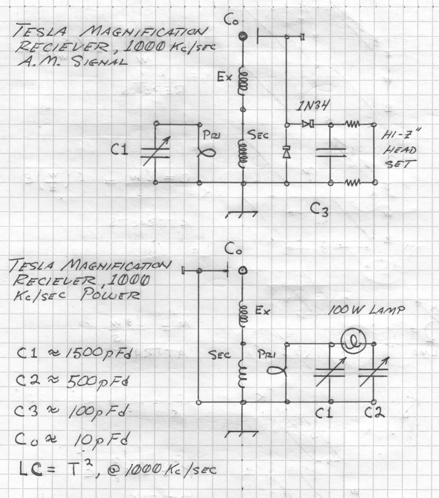
        Jimm, what do you make of this top diagram, in particular the C0 plate, diodes and headphone section?

        Is this a test?
        Fine. It's an interesting adaptation of a "crystal radio
        The amplitude generated at the TC top capacity is loosely coupled into the detector circuit via the pickup plate (which will also affect the TC tuning depending on how close it is).
        You may get some tuning affects with the primary viable cap, but it's performance is dependent upon the coupling setup.

        Comment


        • Originally posted by Geometric_Algebra View Post


          Notes:

          1. Secondary Design Summary:

          D=20in=0.508m
          N=30 turns
          L=pi*D*N= 47.877m
          lamda/4: 47.878m
          lambda: 4*(47.878)= 191.5m
          f=c/lambda=2.998E8/191.5= 1566kcps
          (2/pi)*f= 998 kcps

          2. Split ring is a 0.080" solid copper wire loop of 20" diameter mounted in fixture 0.375" above secondary.
          3. Primary loop(s) excited with 6sn7 triode driver circuit (based on Eric's design).
          4. Current measured via field intensity meter: Simpson 270, 50uA range, 1n34 diode, 2.425" diameter pcb disc terminal. Frequency measured with oscilloscope.
          5. Primary capacitor: 5nf experimental made of pcb plates.
          6. Ground is 10 ft (?) welding cable + 5 copper rods.
          Nice looking build. What did you use for the form supports? did you coat them?

          Comment


          • Originally posted by jimm View Post
            Is this a test?
            Fine. It's an interesting adaptation of a "crystal radio
            The amplitude generated at the TC top capacity is loosely coupled into the detector circuit via the pickup plate (which will also affect the TC tuning depending on how close it is).
            You may get some tuning affects with the primary viable cap, but it's performance is dependent upon the coupling setup.
            It's not a test. I'm just curious, if I was to put up an antenna for a regular crystal radio to receive the overground EM wave, would I hear anything if I put a detector near the antenna? A wire point also works in the Tesla setup, it doesn't need to be a capacitive plate arrangement. Is one antenna supposed to enable me to use another?
            http://www.teslascientific.com/

            "Knowledge is cosmic. It does not evolve or unfold in man. Man unfolds to an awareness of it. He gradually discovers it." - Walter Russell

            "Once men died for Truth, but now Truth dies at the hands of men." - Manly P. Hall

            Comment


            • Originally posted by jimm View Post
              Nice looking build. What did you use for the form supports? did you coat them?
              Hi Jimm,

              The form supports are carved from 1/4" MDF board (Medium Density Fiberboard). The entire pri/sec support structure consists of sixteen identical support plates that are fastened (hotglue) to top and bottom ring supports.

              Here's the material I'm using:
              1/4 in. x 2 ft. x 4 ft. Medium Density Fiberboard Project Panel (4-Pack)-1508104 at The Home Depot

              They are not coated.
              Last edited by Geometric_Algebra; 07-15-2013, 03:24 PM.

              Comment


              • Originally posted by dR-Green View Post
                It's not a test. I'm just curious, if I was to put up an antenna for a regular crystal radio to receive the overground EM wave, would I hear anything if I put a detector near the antenna? A wire point also works in the Tesla setup, it doesn't need to be a capacitive plate arrangement. Is one antenna supposed to enable me to use another?
                Well, it depends... First of all the tesla coil is the "tank circuit" for the setup you have. Without it, you only have a demodulator.
                However if there is a strong em modulated signal nearby, you will hear it, if you are in a metro area, you may hear several all at the same time. That's kind of how the front end of SDR works, by the way. The computer does the sorting/scanning /display. The tank selects the frequency of interest in your case, amplifying it with with the resonant condition.

                However, if you cut the antenna length to some resonant frequency, that would help, but still untuned. A "right sized" variable cap in between might
                help with the tuning.

                Comment


                • Originally posted by jimm View Post
                  Well, it depends... First of all the tesla coil is the "tank circuit" for the setup you have. Without it, you only have a demodulator.
                  If that is so, where is the receiving antenna?

                  Originally posted by jimm View Post
                  However if there is a strong em modulated signal nearby, you will hear it
                  The transmitter is 84km away.
                  http://www.teslascientific.com/

                  "Knowledge is cosmic. It does not evolve or unfold in man. Man unfolds to an awareness of it. He gradually discovers it." - Walter Russell

                  "Once men died for Truth, but now Truth dies at the hands of men." - Manly P. Hall

                  Comment


                  • Originally posted by dR-Green View Post
                    If that is so, where is the receiving antenna?
                    The TC top cap, if I understand the question...

                    The transmitter is 84km away.
                    So you only hear one?
                    You certainly aren't lighting any bulbs from that transmitter!

                    Comment


                    • Originally posted by jimm View Post
                      The TC top cap, if I understand the question...
                      I'm not sure if you didn't understand the question or if I don't understand your answer.

                      I mean, in order to receive a radio signal, supposedly, you need to stick an antenna in the air.

                      You say in the diagram there is only a tank circuit and demodulator. So I say where is the antenna?

                      That is to say, the signal that I'm receiving through the detector/demodulator isn't simply sprouting there out of thin air, it obviously got there somehow for it to be detectable. Therefore the question stands that if I was to replace this whole setup with standard radio equipment, would a detector do anything simply through placing it near the receiving antenna?

                      Originally posted by jimm View Post
                      So you only hear one?
                      You certainly aren't lighting any bulbs from that transmitter!
                      I can tune it to a few others but one is stronger and the coil I had happened to be the right wire length, I know the frequency, radio station and transmitter location so that's the only one I'm interested in.
                      http://www.teslascientific.com/

                      "Knowledge is cosmic. It does not evolve or unfold in man. Man unfolds to an awareness of it. He gradually discovers it." - Walter Russell

                      "Once men died for Truth, but now Truth dies at the hands of men." - Manly P. Hall

                      Comment


                      • That is to say, the signal that I'm receiving through the detector/demodulator isn't simply sprouting there out of thin air, it obviously got there somehow for it to be detectable. Therefore the question stands that if I was to replace this whole setup with standard radio equipment, would a detector do anything simply through placing it near the receiving antenna?
                        What are you replacing and with what "standard radio equipment"?
                        You will have to be a lot more specific.
                        I thought I answered the conditions and what would happen two posts ago pretty well, but perhaps I am not understanding the question.

                        The signal got there by bouncing off the ionosphere using the earth common.
                        Standard radio and the Tesla setup work the same way in this instance.
                        As I said initially, this is nothing more than a variant of the "foxhole radio" or simple Chrystal set that kids have built for decades. Google it.
                        Try the experiments that I suggested if you doubt what I say.
                        To do "untuned demodulation" with just an antenna may require a closer signal source, though. If you lived in a big city it would be easy.
                        As long as you get enough AM signal to drive the headphones, that circuit will demodulate it.
                        Btw, modern schotkey diodes are more efficient detectors for weak signals than the old germanium types.

                        I hope this helped.

                        Comment


                        • Originally posted by jimm View Post
                          To do "untuned demodulation" with just an antenna may require a closer signal source, though.
                          Precisely. Which leads to the point, its signal source is effectively the Tesla receiver. The Tesla receiver's signal source is the grounded AM transmitter. The tuning is done through the Tesla receiver, hence allowing for "untuned demodulation" with the section that you identified as the detector/demodulator much further from the transmitter. Hence my "untuned demodulator" works at 84km.

                          Yes thanks for the suggestion, I've gotten better results by using different diodes, worse with others.
                          http://www.teslascientific.com/

                          "Knowledge is cosmic. It does not evolve or unfold in man. Man unfolds to an awareness of it. He gradually discovers it." - Walter Russell

                          "Once men died for Truth, but now Truth dies at the hands of men." - Manly P. Hall

                          Comment


                          • Pri/Sec + E.C. + Terminal Capacity System Testing


                            Expanded view of first resonant peak:


                            Notes:

                            1. Secondary Design Summary:
                            D=20in=0.508m
                            N=30 turns
                            L=pi*D*N= 47.877m
                            lambda/4: 47.878m
                            lambda: 4*(47.878)= 191.5m
                            f=c/lambda=2.998E8/191.5= 1566kcps
                            (2/pi)*f= 998 kcps

                            2. Extra Coil Design Summary:
                            D=8in (0.2032m)
                            N=46 turns
                            L=pi*D*N= 29.37m
                            lambda/4: 29.37m
                            lambda: 4*(29.37m)=117.5m
                            f=c/lambda = 2.998E8/117.48 = 2552 kcps
                            (pi/2)*f= 4009 kcps
                            3289/2552=1.289 => 128.9%

                            3. Adjustable split ring, 0.080" solid copper wire loops of 20" diameter mounted in base fixture 0.375" above secondary; top ring adjustable in 3/16" increments relative to base fixture. Adjustable plates fastened with 4-40 nylon bolts. Separation distance set to 1.125" for this experiment.
                            4. Primary loop(s) excited with 6sn7 triode driver circuit (based on Eric's design) (approx 100v plate voltage).
                            5. Current measured via field intensity meter: Simpson 270, 50uA range, 1n34 diode, 2.425" diameter pcb disc terminal
                            6. Primary capacitor: 5nf experimental made of pcb plates.
                            7. Ground is 10 ft (?) welding cable + 5 copper rods.
                            Last edited by Geometric_Algebra; 07-19-2013, 05:30 PM. Reason: Forgot coversheet for TPS report

                            Comment


                            • Re..

                              Originally posted by dR-Green View Post
                              What cable do you mean?
                              Hello again,

                              I meant the sensitivity around the secondary coil, as you put your body close to it, and the center frequency changes..

                              I was watching Eric's old video on Tesla's Longitudinal waves,
                              Eric Dollard - Tesla's Longitudinal Dielectricity (Scalar Demonstrations & Wireless Transmission)(360p_VP8-Vorbis) - YouTube

                              At 51 minutes in he starts talking about the two peaks.
                              For that given build he states:
                              1.875 MHz Resonant frequency A, predominately transverse
                              2.945 MHz Resonant frequency B, predominately longitudinal
                              Any coil, radio transmitter, receiver will have both components.
                              Depending on mode of input, the receiver can receive through the ground or an aerial.

                              Then he states what I was considering..
                              If the parasitic capacitance in the coil are reduced to a very small value, then only the transverse wave will predominate, and the longitudinal will disappear.

                              Then he refers to his 4 quadrant equations, etc, explaining the 4 constants that make up the two resonant peaks. Which I really need to start looking over.. The math I mean. It would probably clear up a whole lot trying to decide how to engineer these coils.

                              So I will try to find some local or nearby AM station, and start from scratch. When I get something tangible to show, I will post my pics and data. Thanks for the replies.

                              @Geometric Algebra, looking impressive. Thanks for posting your info.

                              Br,

                              Marcel

                              Comment


                              • So Eric's theory is based on 4 quadrants?
                                Is that correct?

                                And one of the most popular threads on this forum discusses ASYMMETRY?

                                And Jung believed meditating on mandalas based on 4-fold or quaternary geometry was the best way for an individual to achieve 'individuation'.

                                So here is the simpleton premise that I feel SMART/INTUITIVE ENGINEERS should heed based on a particular 'geometry' that has been passed forward since 10,000 BCE.

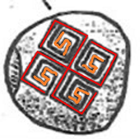
                                This image of a 'swastika' is the world's oldest swastika found to date, found in the Mezine, Ukraine dated to 10,000 BCE.


                                Note the world's oldest swastika on record has 4 quadrants.
                                Please note the ASYMMETRY that I have highlighted in orange ... I did not change any of the lines.

                                555 vs. 5
                                SSS vs. S

                                (world's tallest obelisk - the Washington Monument is 555 feet tall btw)

                                So were the ancients aware of ASYMMETRY?
                                Yes they were in fact!

                                Rene Schwaller deLubicz made the observation in 1949 that the Egyptians abhorred SYMMETRY!
                                And it was not until 1956 that the 4 forces were defined as ASYMMETRIC!

                                It is a FACT that Einstein was not aware of the ASYMMETRY of the 4 forces in 1905, and neither are most of the fellas on this forum aware of how IMPORTANT the concept of ASYMMETRY is to designing a device that is highly EFFICIENT....forget FREE...how about we first shoot for EFFICIENCY!!!!!!!!!!!

                                your egos wanting to be recognized as the savior of humanity by producing FREE ENERGY is a joke....your ego is a yoke.

                                SWASTIKA NANO technologies are ALREADY proving their EFFICIENCY....
                                http://www.energeticforum.com/renewa...-machines.html

                                In other words fellas there are SWASTIKA NANO APPLICATIONS in the 21st century that suggest your efforts on this forum are a waste of time.

                                While 'we the sheeple' dream of a FREE LUNCH in the relative macro world ... dinner is being served in the invisible quantum microcosm.


                                selah

                                p.s.
                                Einstein was not aware of ASYMMETRY in 1905.
                                Einstein was not aware of dark energy or dark matter in 1955 when he died...

                                ...Thus Einstein was 'ignorant' of what comprises 95% of the universe AND that the building blocks used on ALL levels of scaling appear to be ASYMMETRIC.
                                Last edited by Raphael37; 07-15-2013, 12:45 PM.

                                Comment

                                Working...
                                X