Interesting video, AstroNod. From my perspective it seems that the two coils are completely in phase, that is, they always have the same charge at any given time.
See, if the electrostatic field is lighting the flourescent bulbs, then it makes sense that there is a dark spot between the coils. The electrostatic lines of force repel each other, and so between the coils the field should be the weakest, if the coils are in phase.
However, if you tune the two coils correctly such that they are 90 degrees out of phase, then the dark spot shouldn't be there any more... Of if you slightly de-tune the coils then you should get blinking.
Announcement
Collapse
No announcement yet.
Eric Dollard
Collapse
This is a sticky topic.
X
X
-
Tesla Cosmic Induction Generator Experiment #1
Hello Everyone ,
Here AstroNod , I have now 2 Tesla coils hooked them up in serries with the prim. coils .
The video is here Tesla Cosmic Induction Generator Experiment #1 - YouTube
Ok nice Coils from jpolakow and clear photo` s thanks .
Now we all look for those wonderfull effects plasma sphere`s `light` bulbs.
I buy one plasma sphere and try to see it if will give the special effects .
Highlikely smaller space between the coils and more RF power will be needed .
I will do also more experiments with high voltage DC static field between the coils 100 a 500 kVolts .
Plasma arc lights / and field experiments with grounding .
Study Tariel Kapanadze devices and upgrades .
I`ll make a new video where i show the power transfer from one coil to the other . i already did those experiments .
This month i be building the other TMT sec and prim i have one of already . and make more of those basic see if i can stack those coils in serries , and i work on the extra coil for in the TMT system .
Stay tuned
PD7Z worldwide and far beond .Last edited by AstroNod; 04-08-2014, 06:37 PM.
Leave a comment:
-
Okay, thanks John for the explanation & description. The Secondaries of the CIG being far more dielectric than magnetic (plasma) however there are still both dielectric and magnetic lines of force. An Electrostatic Induction of sorts or Dielectric Induction.Originally posted by jpolakow View PostRemember to think of the output between the two coils of the CIG as having both a magnetic and dielectric component.
Induction heaters may be of the magnetic type, or the dielectric type. The induction heater you are thinking of is the magnetic type. It operates by having an extremely strong alternating magnetic field inside a coil. Then, a material which has a high permeability (can contain/hold a lot of magnetism) is inserted into this rapidly changing magnetic field. The strong magnetic field repeatedly polarizes the molecules in the sample to be heated, then switches and polarizes it the other way. This rapid movement inside the sample heats the material. The lesson to take from this is only materials that have a high permeability will be able to be heated this way. Now think of what Eric says about conductors- that they are very good at REFLECTING magnetism, not containing it. Thus things like copper, silver, or gold are good at reflecting magnetism and probably wouldn't be heated as well in this way (but it can still be done). Things containing Iron are heated the best this way. Another way of heating through the changing magnetic field is by actually inducing internal currents in the sample material. Then, resistivity losses (i squared r) heat the material. This is why transformer laminations are thin - to reduce the available material to generate currents in (called eddy currents). With the gold particles being small, only very small eddy currents could be created.
A dielectric heater that I'm sure you are familiar with is the microwave. You put food in, and it is magically cooked. The way it heats is through dielectric induction - rapidly changing the dielectric field inside a material. Thus materials that have a high permittivity (can hold a lot of dielectricity) will best be heated in this manner. Not surprisingly, water, which is mostly what is heated in the microwave, has a very high relative permittivity. The microwave doesn't just have dielectric fields inside it though, it also has magnetic fields- which is why you don't put metal objects in a microwave!
Getting back to your example, if something is to be heated in rapidly changing dielectric fields it is the insulator, not the conductor. Either way, in this case the gold probably wouldn't be heated.
Through very preliminary testing, the CIG seems to produce a much stronger dielectric component than magnetic component. (Which is the goal- to create a plasma via strong dielectric fields between the coils)
The Primary (tank) coil being more magnetic than dielectric but yet it has both components too. The Primary alone would be more like the magnetic induction heater I was thinking of I suppose.
So if the Au or other fillings were in the middle of the Primary coil they might get hot, via magnetic induction, however as it is dielectric induction or a strong dielectric field that the CIG (secondaries) produce it might act more like a dielectric heater than a magnetic heater.
Therefore the Au leaf probably won’t heat up too much. Maybe there could be a dielectric material like bean-bag Styrofoam balls inside a container or glass fibres or something similar? That might be expected to work for a scalar HV DC electrostatic field, but perhaps not so well with a 2Mc Radio Frequency field. However as it’s the null zones that would be of interest to map, perhaps as this interaction might be ‘static’ (or words than mean stabilised) in one particular location at a given distance and frequency, maybe something could be used (other than plasma tubes) to map it as a whole?
Granted though, Plasma tubes are probably the easiest & most practical thing to use that is commonly available.
I know what Eric would likely say, - ‘Build it and see’!
Yeah! Photos of the bush-life and other encounters would be very interesting indeed. - It’s the Coyote channel after all.Originally posted by T-rex View Post
3) if there is interest in photos of bush-life and things encountered I will provide more.
73 DE N6KPH
Leave a comment:
-
Roadside Internet Transmission
1) The Polokowski dark spot in the florescent lamp is unique. It is not the conventional Crookes dark spot nor is it traveling striations. It represents a neutral plane or counterspace between the two coil fields.
2) The blue glow on the glass of power tubes is caused by electron bombardment by the electrons escaping the inter-electrode cavity. it its normal behavior.
3) if there is interest in photos of bush-life and things encountered I will provide more.
4) Tetnus is a physics shill, he is an interesting study to experiment with what really sets him off.
73 DE N6KPH
Leave a comment:
-
I remember you mentioned those Egyptians before. In your videos the travelling patterns also seem to depend on what your hands are doing, have you tried it with the tube on a stick or something so it's away from your hands? I still haven't tried it yet but I think dangling it from a piece of string on each end would be the best way to support it because then each side would also be equal and with minimal contact to other objects. Even the duct tape I use to bind the 8W tube to the end of a stick affects how the tube lights, the tape seems to ground it a bit and cause it to light more than if the tape was not there, so I think dangling from string would be the most neutral method in terms of affecting what it does.Originally posted by Farmhand View PostWhat makes me think twice about the travelling dark spots in the fluro is that
they resemble the cables with bands/spots in the Dendera carvings in Egypt.
See attachment, in the actual carving the dark spots are still there but are more
difficult to see.
Considering I got those effects with 12 volt powered coils and less than 10 Watts.
Cheers
That video with the sine type patterns in the tube was interesting, looks like a lightning storm in clouds in some parts.
Leave a comment:
-
Remember to think of the output between the two coils of the CIG as having both a magnetic and dielectric component.Originally posted by Sputins View PostThat might be about the only excuse one could use to justify to buying one of those vodka bottles with the Au leaf inside! To test it out, see if something happens..
If not, then filter out the gold & drink the vodka. If so, then defiantly filter out the gold & drink the vodka! Lol.
If so, make a proper version for field testing.
I would tend to think the conductive particles would get hot, depending on the distance from the coils etc. Induction furnaces more or less work that way. - It probably wouldn’t result in movement, alignment or polarisation of the gold particles, clumping or spreading out or showing where the lines of force are interacting. (?? don't know) - It would be nice if it did though, something like Cymatics (sand on a vibrating plate) but rather an electrical RF 3D version.
Induction heaters may be of the magnetic type, or the dielectric type. The induction heater you are thinking of is the magnetic type. It operates by having an extremely strong alternating magnetic field inside a coil. Then, a material which has a high permeability (can contain/hold a lot of magnetism) is inserted into this rapidly changing magnetic field. The strong magnetic field repeatedly polarizes the molecules in the sample to be heated, then switches and polarizes it the other way. This rapid movement inside the sample heats the material. The lesson to take from this is only materials that have a high permeability will be able to be heated this way. Now think of what Eric says about conductors- that they are very good at REFLECTING magnetism, not containing it. Thus things like copper, silver, or gold are good at reflecting magnetism and probably wouldn't be heated as well in this way (but it can still be done). Things containing Iron are heated the best this way. Another way of heating through the changing magnetic field is by actually inducing internal currents in the sample material. Then, resistivity losses (i squared r) heat the material. This is why transformer laminations are thin - to reduce the available material to generate currents in (called eddy currents). With the gold particles being small, only very small eddy currents could be created.
A dielectric heater that I'm sure you are familiar with is the microwave. You put food in, and it is magically cooked. The way it heats is through dielectric induction - rapidly changing the dielectric field inside a material. Thus materials that have a high permittivity (can hold a lot of dielectricity) will best be heated in this manner. Not surprisingly, water, which is mostly what is heated in the microwave, has a very high relative permittivity. The microwave doesn't just have dielectric fields inside it though, it also has magnetic fields- which is why you don't put metal objects in a microwave!
Getting back to your example, if something is to be heated in rapidly changing dielectric fields it is the insulator, not the conductor. Either way, in this case the gold probably wouldn't be heated.
Through very preliminary testing, the CIG seems to produce a much stronger dielectric component than magnetic component. (Which is the goal- to create a plasma via strong dielectric fields between the coils)Last edited by jpolakow; 04-02-2014, 12:46 PM.
Leave a comment:
-
Vodka.
That might be about the only excuse one could use to justify to buying one of those vodka bottles with the Au leaf inside! To test it out, see if something happens..Originally posted by jpolakow View PostPerhaps a smaller version could be tried first in a jar to see the results.
If not, then filter out the gold & drink the vodka. If so, then defiantly filter out the gold & drink the vodka! Lol.
If so, make a proper version for field testing.
I would tend to think the conductive particles would get hot, depending on the distance from the coils etc. Induction furnaces more or less work that way. - It probably wouldn’t result in movement, alignment or polarisation of the gold particles, clumping or spreading out or showing where the lines of force are interacting. (?? don't know) - It would be nice if it did though, something like Cymatics (sand on a vibrating plate) but rather an electrical RF 3D version.
Leave a comment:
-
Thats a good idea Sputins. I briefly looked into this when thinking about how to map out the field behavior. One problem I forsee is that the field lines from a magnet are static, whereas with the CIG they oscillate at around 2 Mc, constantly changing. That being said perhaps the field lines follow the same "path" so the suspended particles could stay in relatively the same place. Perhaps a smaller version could be tried first in a jar to see the results.Originally posted by Sputins View PostWhile in a bottle shop recently I noticed Vodka bottles that had some gold leaf suspended inside the bottle. The leaf seems fairly equally spread and even if you shake the bottle the leaf remains in its position. It doesn’t float to the top or sink to the bottom. The combination of the weight the gold leaf to surface area, the viscosity of the vodka and perhaps an electrical charge also put the Gold leaf forms a nice macro colloidal-like suspension.
Just throwing the idea out-there: - Could such a suspension be a dielectric field indicator? As the gold leaf suspension if brought within the field of the CIG, would the particles align themselves with the dielectric field? Perhaps other materials might form a suspension in a more suitable liquid such as mineral oil, together with gold leaf, aluminium foil, or other similar suspension material.
If the (gold) leaf suspension worked and the leaf took the form of the dielectric field, similar to the way iron fillings work with a magnet, this could help map what’s happening within the field of the CIG?
One might have an aquarium sized suspension to place in between the coils?
It may not even work? The particles might glow white hot? Maybe too hard & messy to be of any practical use?
Sputins.
Leave a comment:
-
Gold suspension?
While in a bottle shop recently I noticed Vodka bottles that had some gold leaf suspended inside the bottle. The leaf seems fairly equally spread and even if you shake the bottle the leaf remains in its position. It doesn’t float to the top or sink to the bottom. The combination of the weight the gold leaf to surface area, the viscosity of the vodka and perhaps an electrical charge also put the Gold leaf forms a nice macro colloidal-like suspension.
Just throwing the idea out-there: - Could such a suspension be a dielectric field indicator? As the gold leaf suspension if brought within the field of the CIG, would the particles align themselves with the dielectric field? Perhaps other materials might form a suspension in a more suitable liquid such as mineral oil, together with gold leaf, aluminium foil, or other similar suspension material.
If the (gold) leaf suspension worked and the leaf took the form of the dielectric field, similar to the way iron fillings work with a magnet, this could help map what’s happening within the field of the CIG?
One might have an aquarium sized suspension to place in between the coils?
It may not even work? The particles might glow white hot? Maybe too hard & messy to be of any practical use?
Sputins.
Leave a comment:
-
What makes me think twice about the travelling dark spots in the fluro is that
they resemble the cables with bands/spots in the Dendera carvings in Egypt.
See attachment, in the actual carving the dark spots are still there but are more
difficult to see.
Considering I got those effects with 12 volt powered coils and less than 10 Watts.
CheersAttached Files
Leave a comment:
-
The strange thing about these nodes seems to me that the secondary coil has a length of prox 20 meter or more and that is a quarter wave resonance so the full wave is over 80 meter.
Leave a comment:
-
Tesla published a little bit about nodes.
"The True Wireless" by Nikola Tesla
see Figure 6
Tesla said you can move the node by using a capacitance? at one end.
Consider now the effect of such a conductor of vast dimensions on a circuit exciting it. The upper diagram of Fig. 6 illustrates a familiar oscillating system comprising a straight rod of self-inductance 2L with small terminal capacities cc and a node in the center. In the lower diagram of the figure a large capacity C is attached to the rod at one end with the result of shifting the node to the right, thru a distance corresponding to self-inductance X. As both parts of the system on either side of the node vibrate at the same rate, we have evidently, (L+X)c = (L-X)C from which X = L(C-c/C+c). When the capacity C becomes commensurate to that of the earth, X approximates L, in other words, the node is close to the ground connection. The exact determination of its position is very important in the calculation of certain terrestrial electrical and geodetic data and I have devised special means with this purpose in view.
Leave a comment:
-
A review of a few experiments early 1900 by lecturer Robert Richardson in 1981 Cornell.
He reminds us of some good perspective of current flow, detection methods, nodes, and other ideas :
PHYS Electromagnetic Waves - YouTube
Some scientist made discoveries while electrical storms brewed. Journals kept during episodes of brilliant genius refer to a magnetometer kept on the desk that went wild during an approaching electrical storm. A magnetometers can be as simple as an amplified or modified (DIY ) Gauss meter. I think the relationship is the scientist awareness of the natural demonstration that is from the giant magnetic sphere earth opens the broader perspective that the experiments are not that crazy and the model can and should be improved.Last edited by mikrovolt; 03-29-2014, 10:09 PM.
Leave a comment:
-
I was getting these dark spots in the fluros's some time ago, i could get them to travel along the tube as small cylinder type dark spots, i could get them to go from one end to the other or from both ends to the middle or from the middle to both ends. I'm having trouble finding the video showing the travelling dark spots, i'll post it when I do.Originally posted by jpolakow View PostThese were the two hardest images to come by. This is using a 4 ft long fluorescent tube. These things light up much easier than the smaller tube, so it was harder to get completely dark spots. It was extremely difficult to find two interference patterns, let alone photograph them at the same time. These are the two most impressive pictures in my opinion, even if the interference patterns weren't as pronounced as some of the others.
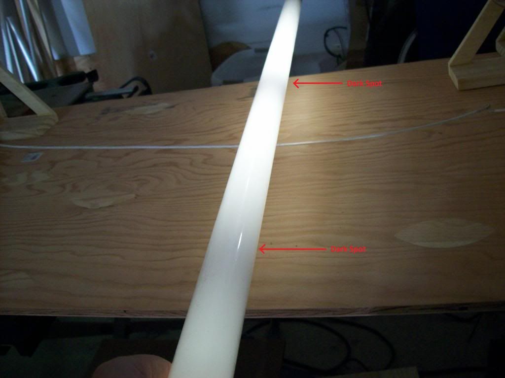
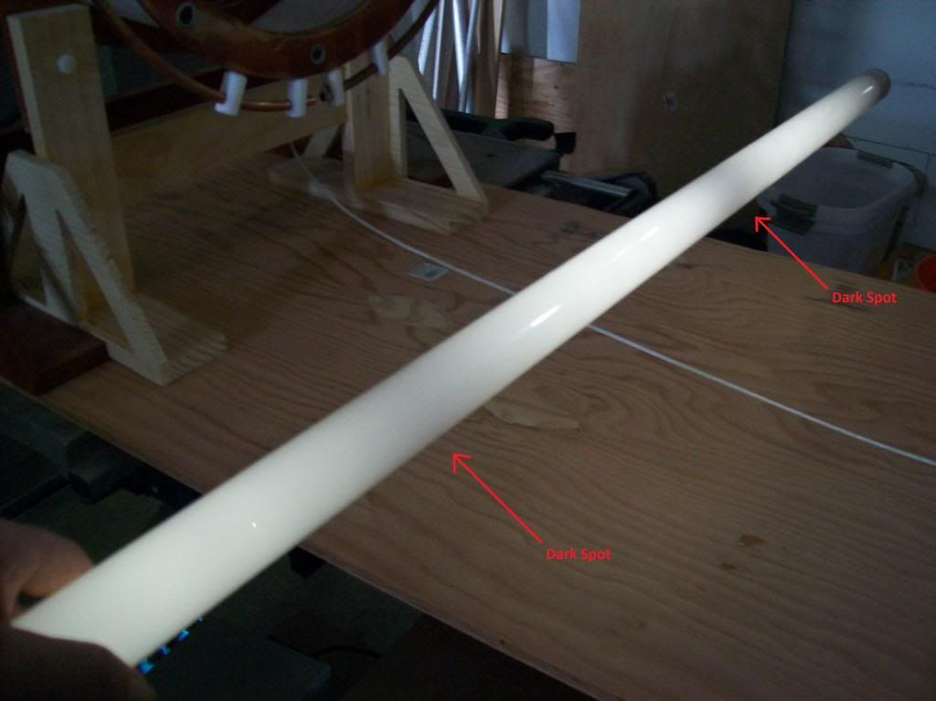
I did some hard thinking after these tests and something immediately came to mind. If I stuck just one end of the fluorescent lamp near the coils, the entire tube would light up. That is, if one end of the tube was receiving enough energy to ionize the gas inside, the plasma would propagate down the entire tube. Here's a couple pics demonstrating this with a 4 foot fluorescent tube, to really show the plasma propagates down the tube:
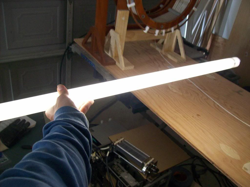
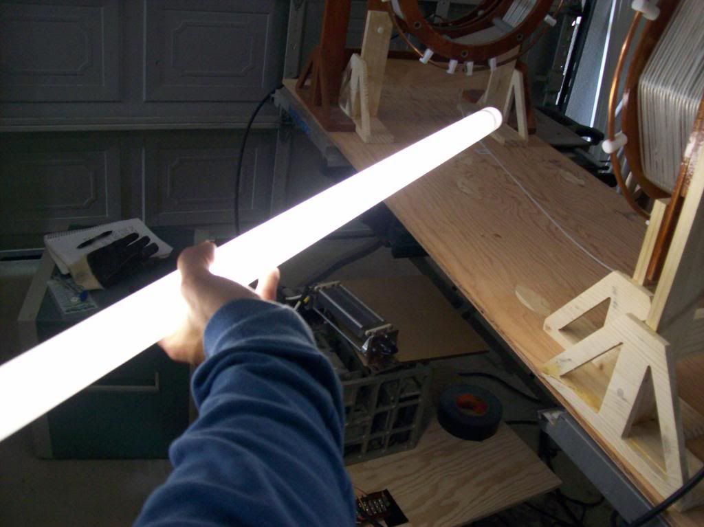
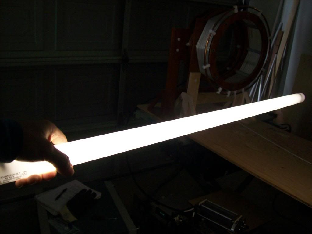
So all it took was part of the fluorescent tube to be receiving field energy and it would be spread through the ionized molecules, and light up the whole tube even if the other end of the tube wasn't receiving any field energy. So the plasma inside the tube tends to spread, regardless of whether or not a field is present. Now this is what seems interesting to me, and please correct me if I am mistaken because I'm not very knowledgeable about plasma but:
This tells me one of two things is happening in the "dark spots"
1. The interference pattern is actively sucking energy away from the tube in this area to prevent a plasma from forming.
or
2. The interference pattern somehow prevents energy from the "lit" plasma being transferred to the unlit regions of the tube.
Any comments or criticism are welcome!
I discovered I could do it back in 2011.
This clip at about 4:45 I show one.
https://www.youtube.com/watch?v=S-XMmlynCLQ
This clip has all kinds of freaky patterns and some dark spot action towards the end.
https://www.youtube.com/watch?v=Gr9JX_sIP2I
Another one.
https://www.youtube.com/watch?v=61psmS8WKTU
Cheers
P.S. Here's one of the travelling dark spot, it could be done almost any time the coils were resonant. If the fluro is held in different ways the spots move in different ways. I'm sure I have a better video but they are not labeled well.
https://www.youtube.com/watch?v=FLuaJHGc-jc
..Last edited by Farmhand; 03-29-2014, 05:39 AM.
Leave a comment:
-
Yes I have been able to get the dark band with just one coil set. Also I I'm able to do it with just the secondaries (I dont have any extra coils yet).Originally posted by dR-Green View PostThank you John. Those are some very nice images on that page! I like the tubes he's using.
I was using just one coil set. I don't have enough voltage to be able to light tubes with the secondary alone (without extra coil), but I assume you should be able to get the same dark spot with just the secondary on your setup (unless it specifically has something to do with the extra coil). I'm not sure if it would still do the same with two coil sets. It would be interesting if either both dark bands are present at the same time producing a "cross", or if it rotates by 90 degrees depending whether one or two coil sets are used.
Another thing I didn't mention is "travelling" patterns using an 18W tube, but so far I've had to hold the tube in my hand and things seemed to be moving to or from my hands, so I'd like to dangle it from a stick with a piece of string and see if the same still happens. This is again with the tube parallel to the coil winding so effectively from left to right, not from top to bottom of the coil.
Yea I was also getting those weird "travelling" striations of thin dark bands. I'm not sure what they are.
One thing that confuses me is that to get a dark band, it would seem to imply the dark spot is at a nodal point of the dielectric field (i.e. a zero value). For the secondary at least, the peak value should be at the end of the secondary. Then the minimum value or nodal point should be 1/4 wavelength away in space right? For the low frequencies we are using this is a significant distance so I'm not sure why the dark band appears there.
I'm currently getting ready to build a dielectric field probe to get to the bottom of this.
Any ideas?
Leave a comment:
Leave a comment: