If this is your first visit, be sure to
check out the FAQ by clicking the
link above. You may have to register
before you can post: click the register link above to proceed. To start viewing messages,
select the forum that you want to visit from the selection below.
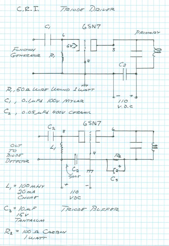
With your setup, you measure 4V dc at grid which gives Ip=4/560=7.14mA. I'm pretty sure that gets you a voltage gain of roughly mu=23V/V with about 6k of plate resistance. The capacitive reactance of your 0.5uF cap at 3.2M is Xc=1/(6.28*0.5e-6*3.2e6)=0.1 ohm. The input net division gives approx 560/560=1V/V, and the output net of your 100k and 0.5uF cap reactance gives the same. At the tube output, a 6K, 33K resistor divider gives 33/39=0.87V/V. So, the ideal voltage gain should be something like A=1*23*0.87*1=20V/V, which would give A*5=100Vpk-pk for a 5v input signal.
I totally agree with these calculations. Thanks gives me something to compare with and a better understanding of tubes.
Someone else had suggested that the probe of my scope that has 30pF capacitance presents around 1700 Ohm (at 3MHz) parallel to the 33k tearing the mu down a factor 3. I tend to agree with that analysis. It would explain my strange scope readings at this frequency. It also means that the tube works fine at this frequency.
I'm not too confident on the power calculations...
The output impedance is 6k in parallel with 33k gives 5k in series with your CR load of z=(100k-j0.1) ohm.
With a 100k, at 5v signal, the tube should generate (23*5)^2/(5k+100k)=0.1W ?
I think this is the power dissipated or lost in the whole output stage?
With 100k removed, direct coupling to primary, Zload=5k+j20 the tube should generate about (23*5/6*5)^2/sqrt(5k^2+20^2)=1.8W (assuming a primary that is all inductance of 1uH or 20.1 ohm inductive reactance at 3.2M)?
I think this is the power dissipated in this output stage. The primary as inductance only would be reactive and not dissipate power in this model? I think that the power that is radiated away through the primary and secundary should theoretically show up as resistance in the load. Certainly if the power is going to counter space
I found out that making a resonating setup of primary and variable cap and tuning the cap to max the impedance of the two still condiderable drops the output voltage and that would mean that a lot of power is radiated away.
The tube parasitics modify things, but how much for those frequencies?
As an experiment you could remove the 100k resistor and connect the primary between output cap and neutral, and then monitor the field intensity meter as you adjust the amplitude and frequency of your function generator.
I am not to sure the 100k is a big problem but you are right I should try with 1M. In audio this 100k is used a lot.
Thanks for the analysis gives a lot of thinking
As a next thing I should measure with the nano or micro amp meter and diode. That seems more reliable than the scope. but no absolute vallues.
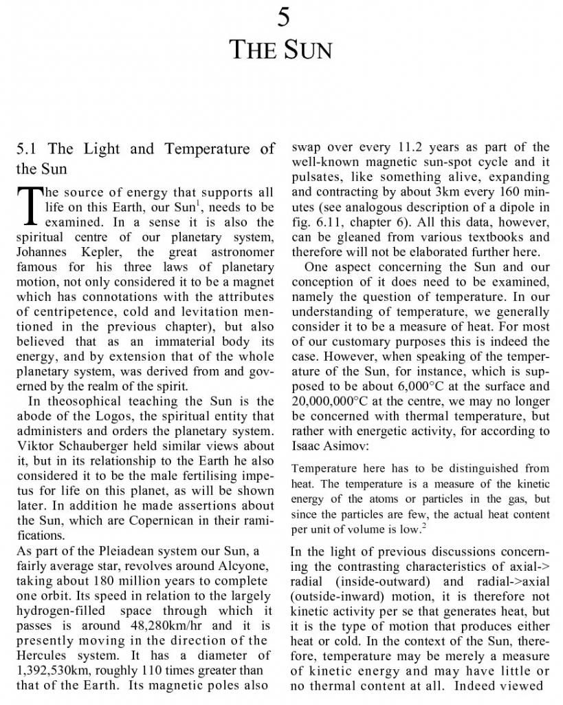
@dr-Green your article about the Sun is dynamite! Thanks!
With your setup, you measure 4V dc at grid which gives Ip=4/560=7.14mA. I'm pretty sure that gets you a voltage gain of roughly mu=23V/V with about 6k of plate resistance. The capacitive reactance of your 0.5uF cap at 3.2M is Xc=1/(6.28*0.5e-6*3.2e6)=0.1 ohm. The input net division gives approx 560/560=1V/V, and the output net of your 100k and 0.5uF cap reactance gives the same. At the tube output, a 6K, 33K resistor divider gives 33/39=0.87V/V. So, the ideal voltage gain should be something like A=1*23*0.87*1=20V/V, which would give A*5=100Vpk-pk for a 5v input signal.
I'm not too confident on the power calculations...
The output impedance is 6k in parallel with 33k gives 5k in series with your CR load of z=(100k-j0.1) ohm.
With a 100k, at 5v signal, the tube should generate (23*5)^2/(5k+100k)=0.1W ?
With 100k removed, direct coupling to primary, Zload=5k+j20 the tube should generate about (23*5/6*5)^2/sqrt(5k^2+20^2)=1.8W (assuming a primary that is all inductance of 1uH or 20.1 ohm inductive reactance at 3.2M)?
The tube parasitics modify things, but how much for those frequencies?
As an experiment you could remove the 100k resistor and connect the primary between output cap and neutral, and then monitor the field intensity meter as you adjust the amplitude and frequency of your function generator.
I was told that grounded grid has the least parasitic capacitance and thus is better for high frequencies. Also nice tube driver to start with.
I only used carbon resistors and MKC caps. This driver should produce aether currents and not electrons
Thanks Jon, I'll give all the data a look over in the next couple days and see what I can find. I'm trying to locate an internal schematic on the receiver, interesting to see what kind of isolation is occurring between it and PS.
Per your schematic the tube is non-functioning. in other words there is no signal on the grid and the cathode R is very small, making for large currents to drain thru it from the plate. What's the goal? I could work up a schematic with values later tonight. it's a simple amp circuit, SE. (single ended)
Hi its a grounded grid. See this Eric drawing:
But the reason why my mu is low might be because the probe from my scope seems to be broken at high frequencies. Have to buy a better one.
Thanks Jon, I'll give all the data a look over in the next couple days and see what I can find. I'm trying to locate an internal schematic on the receiver, interesting to see what kind of isolation is occurring between it and PS.
Basically Eric's schema but I coupled it out to avoid the dc but without the out coupling cap the mu also dropped to 5 at 3.2MHz.
My input is 3,5V from the frequency generator and it has 4Volt dc at the cathode. The anode has 110V dc.
Per your schematic the tube is non-functioning. in other words there is no signal on the grid and the cathode R is very small, making for large currents to drain thru it from the plate. What's the goal? I could work up a schematic with values later tonight. it's a simple amp circuit, SE. (single ended)
JP, the coils look awesome & it�s been great to see your results so far!
Thanks for explaining the connection or phasing concerning the primary coils. In other words the two primary coils should be wound the same direction but the Secondary coils are wound it the opposite direction to each other.
It appears that you are driving the secondary coils at full wavelength, not the quarter wave Ro as such. Is this so? Or are you indeed driving at the quarter wavelength? That is one of the differences between myself and dr Green at the moment. Doc Green has been running a quarter wave Ro while I�m using a full wavelength Ro on the primary tank. What are your thoughts / comments on that? Tesla coils are traditionally driven with quarter wavelength but may not necessarily be so.
I have found with testing my coils (although I only have one half complete at the moment) and as such I omit powering up the main transmitter mostly, although I still leave it connected. Using a very low power driver I connect it directly to the base of the secondary (telluric output, or where your two are connected). Now a frequency sweep can be done while watching the meter peak (mine is a loop-stick uA meter with a variable R pot). I found that when doing this the variable capacitor on the tank circuit can be adjusted �on the fly� which affects the peak on the loop-stick meter and the optimum peak, with the optimum position for the tank circuit capacitor can be found this way. Using that setting I then use the same low power driver to now power the up the transmitter (input) and generally it�s still spot on the optimum setting. Now even with low power on the transmitter the loop-stick meter pegs. Now the variable R-pot on the loop-stick can be adjusted to bring the meter back into range. Turning up the power on the transmitter, I have to take the L-S meter far away so it no longer pegs. I�m making some other non-contact test meters to detect the voltage which should help me further.
However as your graphs show for any given frequency there is an optimum tank circuit capacitance setting, or reversed for any given tank capacitor setting there is an optimum frequency. However there is one which will have the optimum Q or sharpness. Looks like from you graph the one with the 60 degree shaft setting gave the sharpest graph with the peak at 1.96Mc.
As you say, there are many combinations of parameters to yield the maximum power output. It�s part of the fun with experimenting! - Wonderful work Sir.
Sputins.
Hi Sputins,
Thanks for the comments.
Yes you have that right about the coil phasing. The primary direction of winding is arbitrary, but the secondaries MUST be wound in opposite directions. Then the primary connections are adjusted to the proper phasing. Final determination is made by checking with the fluorescent bulb to verify the coils are out of phase.
I am indeed driving the secondaries at quarter wavelength. Why did you think I was driving them at full wavelength?


Leave a comment: