Originally posted by upgradd
View Post
Electromagnetic relations cannot be utilized in this situation.
There is no velocity in space. The velocity is in counter space in per cm per second.
73 DE N6KPH


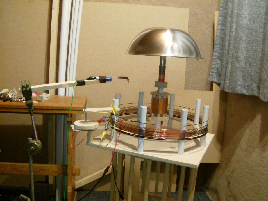
 the whole thing might lift of with that big cap on top .
 time for some more coffee
 De PD7Z / Astronod
 de PD7Z / astronod
Leave a comment: