Output Transformerless Amplifiers
Output Transformerless Amplifiers:
Output Transformerless Amplifiers
Just knew there was more to this and why Eric picked this particular organisation.
Sensibly equivalent� to:- A1834 - CV2523 - EI834 - ECC230 - 6N13S - 6AS7 - 6520 - A4475
Smokey
-
Vacuum Tubes
Geometric Algebra,
"Coyote letter regarding 6AS7G/6336 tubes and a HF transformer/MK network model.
Letter: 18-JAN-2014"
Thankyou for that.
The other Tube Eric was searching for is a 6520 which is a 6AS7G.
Good information as I had ample here of medium and high mu but only a couple of low mu in the 6J6 and 6S4 and this answers the question as to what they were used for and why.
Slow here and working with the Hendershot Generator and Magnets and Geiger Counters and making it rain, or trying to and this keeps me off the streets.
Some excellent work being done and will be back soon.
Sputins,
Can't help with the bulb but do have 2 x Carbon filament here for 110v that look very similar.
SmokeyLeave a comment:
-
Bulb Type?
What is that bulb? Is there someone in the know that could help me please?
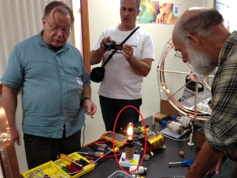
As per the Mark McKay�s replication of Eric�s original Radiant Electricity demonstration, what is the type of bulb used for the Radiant output? (Circled in red). I believe it is a long slender type of vacuum bulb?
I know the bulbs used for the termination (reflection capacitance) of the spiral coils are a General Electric type NE-34 vintage bulbs. (These are quite rare and expensive these days). However I�m interested in sourcing one of those long slender vacuum bulbs. If you know (and prefer not to publicly disclose what type they are, lest they are also rare) please PM me. I only want one unit. Thanks
Sputins.Leave a comment:
-
@dr Green, you�re right, that is what the sting is, arcing to the fingers when the terminal is loosely held. I even received a slight burn through the insulation of the larger clamp, so the current can penetrate the insulation seeking a ground. Penetrate is the wrong term, it was if the current conducts through the (so called) insulation. One is better off to just to grab the metal. No problems. The larger the surface area of the held metal definitely helps. Yeah, less contact or varying the pressure of contact affects the brightness of the bulb. - Love the conventional dismissal comments, wires up the sleave of your woollen jumper hey? Lol.Originally posted by dR-Green View Post
Now your amp is able to cleanly transmit music or signals which would be quite practical. Mine cannot as yet, but I might be able to modulate the key in some way to transmit some intelligence. (Morse code or other). Perhaps I can modulate the grid. The next push-pull transmitter will have (music) modulation as a feature.
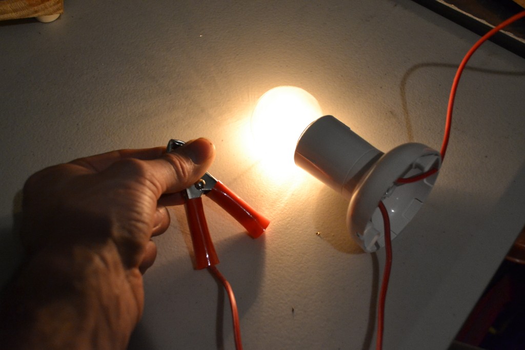
Light bulb lit, with the connection from coil to my hand seen.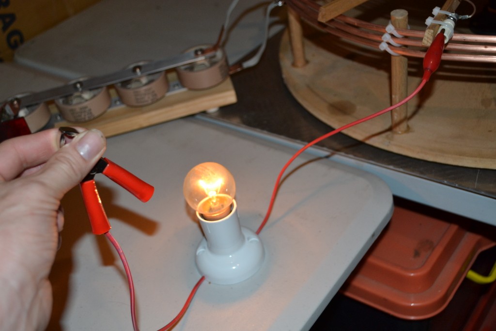
Nothing up my sleeve either... The bulb is much brighter that the pictures show, the camera flash affects the picture.
Light bulb close up:
Now it�s time to go down to the local oval and look like a lunatic measuring out the wire for the extra coils..Leave a comment:
-
40 meter ham band T.M.T.
Hello everyone , here a post of the first update on the 40 m HAM band TMT. all calculations by basic dr.e.d. calculations .
I did put up a photo` s of the form made of TRESPA high-pressure laminate and 19mm white PVC rods . The center have a holder for a glasfiber pole to hold the coils in place like a steady antenna .
disign frequency is about 7060 KHz
i took a sec. coil of 6 turns , diameter is 358mm, wire diameter/coax braid 8mm and 5.5mm space 78mm highcoil wire l. 6,75m L=19uH and Sc=24pF
Fr=7.45MHz with 5,8tap the ring cap can de about 4 pF Helical Coil Calculator
I will make special ring caps they come on the pole .
The extra coil is about 16.675 meter long wire , 143mm diameter ,8mm coax , 5,5 mm space , 50,5uH 8.7pF about 2 pf to tune to the ring cap . Fr=7.75MHz at 36.7 tap some room for ring cap.
no space for `real` extra reflection cap on top for extra coil.
I`ll try this out then i make a nother extra coil with less on the coil like 1/8 wave on coil and 1/8 wave delay and reflecting cap .
I made calculations to for a AM broadcast receive TMT on 675KHz here in the netherlands it would take about 300 meter 8 mm coax .
however i might pull 1000 watts or more of the transmitter site close by the site .
i will post the radio maria AM MW TMT later on .
show you some more within some days the coils and basic measurements.
greetings de PD7Z Last edited by AstroNod; 01-31-2014, 12:36 AM.
Leave a comment:
-
Eric Dollard answers questions on Facebook
New interview video with Eric - Eric Dollard answers questions from Facebook - Jan 27, 2014 - YouTube
Eric answers a bunch of questions that were posted to him through his Facebook account: http://facebook.com/ericpdollard - Give his Facebook page a like!Leave a comment:
-
Thanks Sputins, nice work yourself, I was going to ask if you had tried holding the bulb yet. I always have a chuckle to myself when I think about it. But the conventional dismissal explanations can be even more amusing than the truth, in the past some have tried to claim that the current is going through the sleeve of my woollen jumper to complete the circuit and that it would be very painful etc!Originally posted by Sputins View Post
I would think that the burning is a bit of arcing into your finger, that can sting a bit, but as you say once contact is made and you hold on tight then nothing can be felt. If you use varying power levels you should also be able to see the difference in bulb brightness between "light" connections and gripping it tight with both hands etc, which translates to the importance of all the (ground) connections ideally being soldered and as broad as possible like Eric says, sheet or strip from the coil output to ground etc. I'm still using alligator leads but I think you will find in an obvious way that ideally you shouldn't.
An extra coil can make a significant difference in output for the same input. Personally I've also found the DMT/TMT style coils to be a lot better than my flat spirals, so it should be quite impressive with your amp. I've gotten a lot worse results than these using spark gaps and thousands of volts in the past, so things are progressing nicely I would say, considering it's now also possible to use the same setup for transmission of CLEAN intelligible signals. It's taken long enough to finally come up with an amplifier that's up to the job though! We'll find out how much more power can be squeezed out of it when my power resistors arrive hopefully tomorrow.Leave a comment:
-
Lighting the bulbs.

Fantastic results dr Green! The light bulb pictures tell the story. Lighting a 15W filament bulb with just one wire and the capacitance / grounding of your body. Very impressive.
I can report I did the same/similar thing last night for the first time ever! - A 25 watt filament bulb lit to near full brightness. Starting off with low power and a shot of scotch for courage, I held the wire from the bulb and it lit up! I then increased the power incrementally until full brightness was achieved. It�s a strange thing and a strange feeling to do for the first time! I found that if I lightly grab the wire from the bulb it hurts, or feels like its� hot or burning, but gripping it tightly for good contact you feel absolutely nothing! (Pictures of this to come).
I�m running no extra coil as yet, just the (spiral) secondary and a terminal capacitance only. So I will hopefully improve my results with an extra coil, further tuning and matching the primary & secondary masses.
The thing is that your results are far more impressive than mine because you are lighting similar bulbs and doing it with one-tenth the power! So that is very impressive indeed. Great work, rewarded with the results. I�m sure you have other configurations & experiments in mind, by including the receiving coils etc. Always interesting to see what your doing.
Sputins.Leave a comment:
-
Progress/updates report.
Making tuning condensers for the secondary with Perspex and MDF with a sheet of aluminium tinfoil stuck on. Disk mounted on countersink screw and nut allows for adjusting the gap distance/capacitance through rotation.

Secondary tuned to match the characteristics of Tesla's full scale Colorado Springs coil (also fashioned a new slightly bigger disk for more capacitance and bigger gap)

Output stage upgraded and configured as bridge amplifier, testing is limited to the 15 ohms of output resistors pictured but lower value resistors are in the post to find the limits of the components. Output is generally limited to +/-8 volts without distortion. Apparently it's normal behaviour for audio amplifiers to output up to approx half the rail voltage, above which the signal starts to distort. So about +/-8 volts seems to be the limit here too. Power supply is regulated +/-15 volt 1.5 amp (max).

Working range of fluorescent tube is extended as a result of amplifier modification, can now be used to detect the field potential along the secondary too

Testing with a 15 watt 240 volt bulb

Like it says


Connected between coil output and ground plane. Not full brightness for obvious reasons
 Last edited by dR-Green; 01-29-2014, 11:17 PM.
Leave a comment:
-
6 Eric Dollard Updates
* 6 ERIC DOLLARD UPDATES * - Indiegogo Success, Teslacoin, New Interview and other...
In case you haven't seen the news - an anonymous donor generously donated $10,000 to Eric Dollard's Indiegogo campaign night before last! That brings the total amount raised to $15,283! Check it out: URGENT - Save Eric Dollard's Telluric Project!
That means the $10,000 required for the bond for the Advanced Seismic Warning System is secured and the rest will go towards equipment for the project. Thank you to each and every one of you who donated no matter the amount.
If you can donate to the campaign or ask others to, that would be much appreciated! You can also donate by Paypal at this email info at epdlabs.org - that will be added to the equipment fund for the project.
You can also donate by Bitcoin or Litecoin - the addresses are in the left column at Eric P. Dollard - Official Homepage and guess what??? There are a lot of new crypto coins like those and one with the coolest name ever is Tesla Coin! It was just recently released and we set up Eric with his own Tesla Coin address and the founder of Tesla Coin donated 10,000 Tesla Coin to him two days ago!
Each coin is worth only a little bit right now, but down the road, it could turn into something significant. The idea behind the coin is to help support Tesla Technologies so who better to donate Tesla Coin to than Eric Dollard? And, officially, A & P Electronic Media is the first business in the world to accept Tesla Coin and it is for our digital Ebooks and videos. You can see the details here: A & P Electronic Media - Digital Publishing by Aaron Murakami & Peter Lindemann
Here is a new interview I did with Eric Dollard two days ago. This was over the phone and we discussed this campaign, the Cosmic Induction Generator that John Polakowski has been working on with Eric and Eric's upcoming presentation at the 2014 Energy Science & Technology Conference. Eric Dollard Interview - Advanced Seismic Warning System - Jan 27, 2014 - YouTube
You can hear Eric talk about the demonstrations he will do at the conference and there will be a couple "FIRST TIME EVERS" that you will get to personally see at the conference. You'll want to register here right away to make sure you get a seat > Energy Science Forum Technology Conference 2014, formerly known as the Bedini-Lindemann Science & Technology Conference
In the next day or two, I'll be posting another video with an interview with Eric where he answers a lot of questions that have been sent to him in his Facebook account here: http://facebook.com/ericpdollard - since they are private messages to him, I'm getting the final permission from the last couple people that I can show their post with their name. This covers a wide range of different topics from Eric's Toyota Corolla to the Jupiter Effect to listening to Earth Sounds, etc... I'll send a link to you as soon as it is posted.
Please help support Eric Dollard's work by forwarding this email to everyone you know that is interested in Tesla Technology and feel free to copy and paste this into your Facebook pages and elsewhere.
Sincerely,
Aaron - Eric P. Dollard - Official HomepageLast edited by Aaron; 01-30-2014, 07:18 PM.Leave a comment:
-
Conference Update & Eric's Indiegogo Campaign Update
John Polakowski's bio and presentation for the 2014 Energy Science & Technology Conference is updated: Energy Science Forum Technology Conference 2014, formerly known as the Bedini-Lindemann Science & Technology Conference
-----------------------------------------------------------------------
Eric's Indiegogo Advanced Seismic Warning System update -
Up to $15283! URGENT - Save Eric Dollard's Telluric Project!Leave a comment:
-
Gosh damn Sputins. You've been busy. Looks good.Originally posted by Sputins View PostLeave a comment:
-
Coyote letter regarding 6AS7G/6336 tubes and a HF transformer/MK network model.
Letter: 18-JAN-2014Leave a comment:
-
Hi ya Sputins , thx for the reply. indeed the netherlands here , your from australia great distance about 16 thousend miles , nice for radio experiments.Indeed E Dollard is a great teacher ,and so much more .
Great Disigns he did put here on the forum, i know a am a little late but better late than never. Some disigns i did not understand good enough to give comfort to build a model however now i do understand it better and figured most basics out, i will make copy of the disigns here put on the forum . Like T.M.T. / Camp david Antenna logp. those 2 i`ll will do for 100% sure . The C.I.G. i might do to when the time is there . i think there are more ways to do the CIG . Like wise the 2 basic spiral tesla antenna ` s only with both coils TX at the same and both coils same direction w. turns . That would give a Huge dielectric Flux between the dielectric antenna tops . And ofcourse the signal TX can be modulated to get special effects . A extra RX antenna that feed the modulator that i would think to try . Okeh on the Data of your Tesla flat spiral , i did look closer and indeed there is the special way of build the spiral to give more self capacitance to the spiral .I made 2 of those ones to on a frame just the secondairy ,did nothing with them due to the experiments with the basic wireless tesla system with the normal spiral mostly i use 1/16 wavelenght at c phi/2 on the spiral and 1/16 delay line with top load total , groundplane is also 1/16 wl. squire
topload is about 25% groundplane . from the groundplane can be a extra connection to earth for telluric . at short range 8 meter or less with my 11meter band model i dont need the earth connection to transfer power. however there is a point the longitudinal will drop at greater distance due to no ground connection with a good ground/earth highlikely much bigger distance like wise seawater. This sett up do need the groundplane i had no good transfer with no groundplane .from the groundplane to a conducter plane /earth / `ground` than i had total power transfer . Perpaps a TMT would like to have a small GP before the telluric power goes Telluric via earth connection . Even the groundplane will search the earth it self to sett up the link. However the ground plane can be smaller with the TMT due to the total high of the systems till the dielectric top of to make it a little more confusion the reflection capacitance in the TMT system . If the delay line is longer to the dielectric top sure the groundplane should be larger .Natural at low frequency` s and with long delay lines a groundplane will be not practical and a ground wire system is more likely just under the ground likewise with antenna systems from 4MHz and lower .The Camp david Antenna shown on the forum for 7,1MHz use a Ground system to for the telluric input/ output. however the system will work fine in hertz mode 100% with elevated radials. I do not know if a TMT with elevated radials will transmit hertz wave , to make sure it will just make the extra tesla coil smaller likewise 1/8 wl at system speed. and longer delay and line 1/8 wave include topload . Perpahs Marconi did look to a TMT and hooked the prim to ground instead the sec. that was a shorter connection , i still find it strange that tesla did not not do anything with the hertz component of the tesla system . the first systems he made where hybrids.
Okeh Back to your Coil , Yes 50 watts in the house hihi . i did pop on remote light with just 4 watts at 15 meter distance the shockwave is enorm form the `topload` . i did see also strange effects with the antenna` s rx tx lab sett up . materials fall close by the antenna sometime wierd sound like ghosts just out of nowhere at the antenna site. the model i had on about 9MHz in my room had the toploads close to the roof , one day i did hear like if there was hail falling on the roof ticking noise just at the spot above the antenna tops. Yeah thats fun to drop the TV when someone is into the football game i use to had the keys for the cable tv connection boxes , i did pull the coax out while my friend did look what he would do to his tv when i pull the plug he banged on the tv and i put the coax back , so i did turn him back on when he hit his tv i gave his signal back .... your up next i hear how it will go with your neighbours.
Okeh the CIG yes i did see your frame at the forum for the GIC nice pro. Great if you have that working fine . you could make 2 lose standing TMT and config them to CIG so the dielectric top of both systems are close to each other , like 1 a 5 feet . all kind of lamps would be nice to try like neon argon xenon ect ect . perhaps better is to hook the special lamp to the output of the extra coils so the lamp terminals would be the dielectric top. there are those kind of lamps for lab use ect . dr rife did use also that type of lamps .
you could make a shield in you hobby room with alufoil and if you experiment with 5 a 10 watt in the house must be ok .
thanks for the TMT data on TX an RX coil winding for all the coils .
For what i could see on the photo` s of the original CIG the prim coils are in serries did see just 2 feed lines come out under the table .
so you say in diople mode the TMT one is total right turn and the other half is left turn . Perhaps you know the prim. connection data parallel or serries can be serries cross connection to depend on what you have and want .
Good luck , with all the work .
For now i am almost done with the coils base of one TMT for prim and serries , than i can put the coils on them and test the 2 coils and couple ring cap . i will show the data and perhaps some photo` s of the TMT for the 40 m ham band .
all the best .
john de pd7zLeave a comment:
-
$15,000 raised!!!
An anonymous donor just donated $10,000 USD to the campaign!!!!!!!!!!!!!!
That you to the Angel who graciously supported the project - speechless! We're up to $15,000 so far! The Bond money has been secured and there is $5,000 to go towards equipment! At this rate we'll probably hit the entire $25k goal for equipment and anything over that will go towards purchasing the building for the lab. AWESOME!
Including the founder of Tesla Coin who donated 10,000 Tesla Coin to Eric's Tesla Coin account today too! Wow!
Donate here: URGENT - Save Eric Dollard's Telluric Project!Leave a comment:
Leave a comment: