Announcement

Collapse
No announcement yet.

Eric Dollard

Collapse
This is a sticky topic.
X
X
 
  • Filter
  • Time
  • Show
Clear All
new posts

  • Sputins
    replied
    Originally posted by AstroNod View Post
    Hello Sputins , your coil looks great , what is the lenght of the flat sec coil? about 15 meters?
    due to the skin effect depth the silver have no real use the layer is to thin .
    Calculator for a.c. Resistance of a Round Straight Wire
    at 1.7MHz it is 48uM the silver layers is much thinner, so it will penetrate to the copper layer of the braid .
    copper wil do just fine save` s monnies on the expansive silver coax.
    how much was the input power from the 807 tubes?
    did you use any formula to build this one?

    At the moment i starting to building a TMT for the 40 M HAM band about 7050 MHz . ill post photo` s and calculations within some week .
    the plan is to see how far and how much power it can transmit telluric trough sea water. so i will build 2 pcs if the model is working fine that will be great to for the cosmic induction sett up .
    i do have some question about the TMT , with other the flat spiral the TX and RX coil are wound the other way likewise the prim .
    does the TMT in RX and TX setting need to have left and right turn coils perhaps some one can give my some tips .

    all the best .

    john
    @John (AstroNod) & All. – Hello, It’s nice to see your experiments and results, that’s kinda what this forum is all about isn’t it? From the Netherlands hey, wow. So now there are people from the US, UK, Australia and the Netherlands, experimenting with the concepts of Tesla and following the teachings of Eric Dollard.

    Eric says that the TMT (TX) coils should all be wound in the same direction with all of the receiving coils (RX) also wound in the same direction, but the opposite direction to that of the transmitting coils. IE the transmitter set of coils are wound clockwise and the receiver set wound counter-clockwise. (Or reversed it does not matter). One set of coils is the mirror image of the other. The primary, secondary and extra coil are all wound in the same direction and for the ‘image coil’ they are all wound opposite.

    My spiral coils are modelled on Eric’s original spiral coils. They are two times ten turns for twenty turns total. The length of RG178 co-axial is 25.5 meters. The natural resonant frequency of the coil is measured around ~2080Kcps. With the terminal capacity it brings the Ro down to ~1780Kcps. The maximum input power to the tubes at the moment is around 50 watts, (if that, I usually reduce the power down a bit, but I can increase it up to the full 100 watts). (Two parallel 807 tubes, single ended). With only very short blasts late at night for testing right now. As it is not configured in the CIG mode as yet, there would be some minor transmitting going on. Hams are limited to a maximum of 100 Watts in this country, with some talk of increasing this to 1KW but this has not happened as yet.

    The ground plain is just a 1 meter square sheet of aluminium, which isn’t even connected to the earth as yet. (An earth connection is part of the next phase of the project). With only 50watts the TMT already interferes with the touch-lamp inside the house and the TV picture begins to pixelate, (the wife gets mad, but it’s kinda funny to me as she has to deal with a strobing lamp and a weird TV picture). With the telluric output of the coil connected to ground I’m sure the whole TV picture would just disappear like magic, likewise with all of the neighbours TV’s. (It’s tempting to wreak havoc with the neighbours when the football is on, just as they are lining up for a goal, flick the switch and the picture goes out! Hehe, err perhaps not though, as all arrows would certainly point towards me).

    I can understand what Eric meant by ‘burning down your neighbour’s house” or the “whole dot-com reality going into melt-down”. With a powerful TMT system sending Longitudinal Telluric Waves into the earth, it would wreak some havoc with the local electronics! So for experimentation with non CIG configurations (I.e. a TMT only) it is wise to stick to lower power systems, like dr Green has done / is doing. You can get some good results and the neighbours won’t be quite so upset. Although if your TMT is in a remote location, this may not be a problem. Using sea water for a medium as you are suggesting may also be a reasonable idea.

    I’ll be focusing on the CIG configuration as this should limit the wife’s and neighbours woes and restrict the transmission to a local zone only, so I can operate with the higher levels of power.

    Sputins.
    Last edited by Sputins; 01-28-2014, 03:01 AM.

    Leave a comment:


  • Aaron
    replied
    Advanced Seismic Warning System interview

    Here's a new interview with Eric Dollard - Eric Dollard Interview - Advanced Seismic Warning System - Jan 27, 2014 - YouTube did this today by phone.

    URGENT - Save Eric Dollard's Telluric Project! Eric Dollard interview by Aaron Murakami on Jan 27, 2014. Discusses the advanced seismic warning system project and the indiegogo campaign to raise funds for it. Also covers the Cosmic Induction Generator and the 2014 Energy Science & Technology Conference where Eric Dollard will be the keynote speaker and will be giving a LIVE DEMO! http://energyscienceforum.com/energyc... - even a bit about Tesla Coin - the founder donated 10,000 to Eric Dollard!

    Please share the video with others...

    Another will be posted soon that answers questions that have been posted in Eric's FB account.

    Leave a comment:


  • AstroNod
    replied
    Hello Sputins , your coil looks great , what is the lenght of the flat sec coil? about 15 meters?
    due to the skin effect depth the silver have no real use the layer is to thin .
    Calculator for a.c. Resistance of a Round Straight Wire
    at 1.7MHz it is 48uM the silver layers is much thinner, so it will penetrate to the copper layer of the braid .
    copper wil do just fine save` s monnies on the expansive silver coax.
    how much was the input power from the 807 tubes?
    did you use any formula to build this one?

    At the moment i starting to building a TMT for the 40 M HAM band about 7050 MHz . ill post photo` s and calculations within some week .
    the plan is to see how far and how much power it can transmit telluric trough sea water. so i will build 2 pcs if the model is working fine that will be great to for the cosmic induction sett up .
    i do have some question about the TMT , with other the flat spiral the TX and RX coil are wound the other way likewise the prim .
    does the TMT in RX and TX setting need to have left and right turn coils perhaps some one can give my some tips .

    all the best .

    john
    Last edited by AstroNod; 01-27-2014, 11:27 AM.

    Leave a comment:


  • Sputins
    replied
    Transmitter test with Spiral Secondary Coil

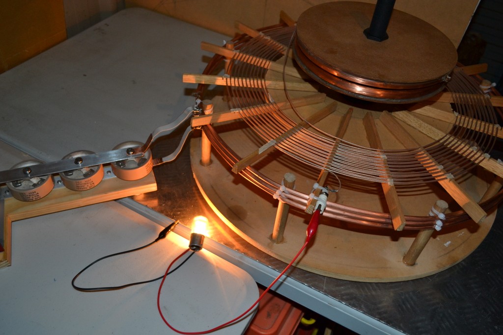
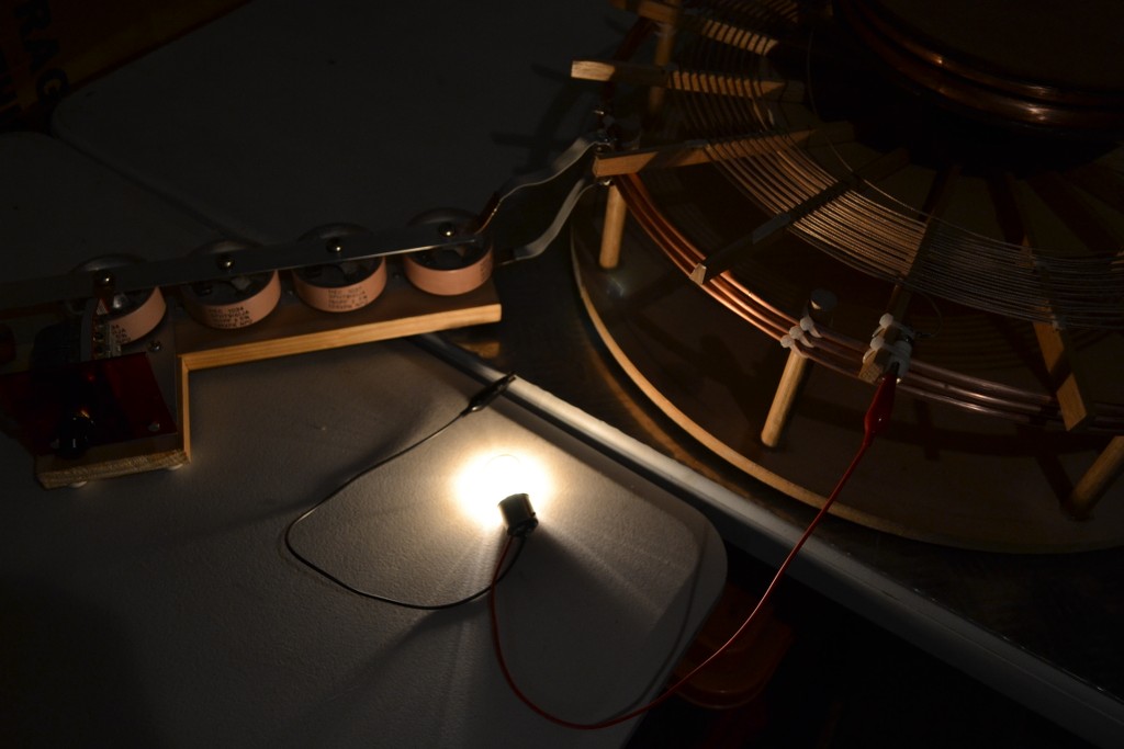
    Further and tests and analysis is yet to be done, however in order to test out my 6AG7 / 807 CW Transmitter on an actual coil, I've built a 'test' three turn primary (with one and two turn taps). This to see what happens when the spiral secondary coil (secondary only) is driven at its self-resonant frequency. With the top capacitance shown this brings the frequency down to ~1.78Mcps (from 2.08Mcps) Further tests with various couplings and so-fourth are yet to be done along with the extra coil in place. However with the primary tank circuit tuned and the impedance matched, the light bulb lights up, well beyond to what I was expecting!

    The light bulb is a 240V, 15W pigmy bulb which is lit to around twice its normal brilliance at least! It is connected to the secondary 'Telluric output terminal' and a ground plane. Small arcs can be drawn off the top capacitance terminals also. There is still much room improvement and extra coil experimentation and receiving with the other twin spiral coil of course along with the CIG configuration. Other coils as per the standard TMT dimensions given by Eric are under construction and testing also.

    Let the photos speak:


    It's wonderful to see the $4800 raised so far for the Advanced Seismic Warning System! I'll be throwing in my contribution soon too.

    Sputins.

    Leave a comment:


  • AstroNod
    replied
    Tesla marconi Antenna

    Hello From the Netherlands .

    Its been some time due to work but here i am agian .
    I`ll post my photo` s of some tesla marconi systems i made .
    this system have no ground connection just a groundplane for testing.
    the groundplane is the reflection cap. the reflection GP is good enough to made contact with the other antenna , sure when connect the GP to the earth / sea / conductorplane the signal get stronger into the other antenna . however for lab experiments the signal is strong enought due to the good GP .
    The standing wave in the transformer is the dif. between 2/phi and lightspeed on freq. the model on the photo ` s is made for CB band 27MHz
    i did work DX with it to in hertz mode .. so its marconi tesla system hybrid.
    the dielectric Ant. is about 25% of the GP and the GP lenght is de delay line + dielectric antenna . the coil is about 1 meter long so is the GP and delay (hertz radiator + top load ) and dielectric antenna top.
    with 25% i mention a plate not a sphere like on the photo.
    a metal plate or alu foil is easy to tune for max power transfer .
    my final antenna have a alu plate square with edge on top like diamond.
    i`ll post photo` s of the final antenna ` s later .
    Area sec coil = Area prim coil . not volume.... like normal V ,but volume with the skin effect etc. so i dont use volume just area .
    i made this antenna for other frequencies to, the more resonance wire the more gain. the lower the frequency the more gain .
    pri. coil more L is better than C use as much windings possible .
    like wise why not 3 or 4 windings if possible it might be better for Z load to the antenna tunner and or x mitter to however more L is more E
    I use online calculators and my own calculator for modeling ,without them i am helpless....
    there are minor mistakes with the TMT calculations formula from members and dollard. dollards basic is good, members make faults ...
    I did see a short video mr E say : we the members `are not too smart` hihi.
    tentative coil nr 6 calc. is N= le/l1 not N=ls/l1 now wire lenght is ok with turns. le
    than use this online calculator Helical Coil Calculator
    you see L and self cap . however in concentrated mode you need a ring cap ! or likewise... don` t do the tandem. less E and highly complex
    the ring cap get close to the coils . however use smal ring caps ! 1 a 3 inch like wise 2mm copper or 2mm silver teflon coax for high hf like 40m band , 7100KHz . a good way to start is first think of your ring cap. load to the self cap load of both coils , that you can count in to the disign of the coils with calculators.
    so place the ring cap at the tentative coil setting on higher freq. bands other wise you dont make it and you will get stuck with 1/4 wave shrinky .... and too much cap. even mr e d doubt his own belive before but i think he recoverd from that... hihi .
    with the online cal. you can change parameters wire diameter and spacing ect. use slightly higher coils and bigger wire !
    in my next posting i give some calculation for ham bands like 40 meters .
    ok before i forget the prim coil. here is the cal .
    Flat Spiral Coil Calculator
    than use this one online to see if you close to resonance .
    Resonant Frequency Calculator
    use small C most L as possible . 50 a 200pF var. C is enough.
    that it for now perhaps i save you some time and monnies .
    good that eric and lab team are building a HQ earthquake detector system now i can test my earthquake device soon .. just kidding .
    i my next post i show some supernova data just before big earthquake.
    Helical Coil Calculator
    Flat Spiral Coil Calculator
    Resonant Frequency Calculator
    i did upload some photo` s there old ones.
    the antenna ` s i make now look a whole lot beter like pro.

    next time i show a new antenna disign for hertz but with tesla coils and wardenclyffe / TMT upgrade to plasma antenna, NATO is gonna love that one.
    if there is any HAM on the forum who like to go telluric or via the ionosphere thats fine with me .
    tonight i made contact with australia on the 40 m band vk3kcx and we had a chat with digital radio mode ROS . i use a us patent http://www.aktuellum.com/circuits/an...ts/2537191.pdf
    i am from the netherlands thats the other side of the world 16620km away from the other station .
    i have 2 windings 86 m wire total in 2 loops of 43 meter with feeder line and antenna tunner it works on 40 20 10 meter bands .

    okeh keep up the good work so do i , post you some more when i can .
    thx to all the members post i did see some lovely photo`s and creations.

    sk de PD7Z
    Attached Files
    Last edited by AstroNod; 01-23-2014, 11:25 PM.

    Leave a comment:


  • Aaron
    replied
    41% to $10k goal for bond!

    $4066 has been raised for the $10k bond!!! 27% to almost 41% of the $10k bond gold in just the last few hours!!!

    Come on everyone, please help share the word - this is happening!

    URGENT - Save Eric Dollard's Telluric Project!

    Leave a comment:


  • Aaron
    replied
    Save Eric's Advanced Seismic Warning System

    We've hit $2676 already out of $10k needed for the bond! The campaign is for $25k, but it is the $10k that is the most important. Anything over that will go to equipment. $2676 out of $10k in 2 days is really encouraging!

    2 more vids are here:
    Eric Dollards Advanced Seismic Warning System | Indiegogo

    I'll be posting the full length video interviews with Eric soon....

    Please donate! URGENT - Save Eric Dollard's Telluric Project!

    Leave a comment:


  • Aaron
    replied
    Save Eric's Telluric Project

    Hey everyone,

    If you're able to even donate just $5 to say thank you, please do so.

    --------------------------------------------------------------------

    Hi,

    I (Aaron) just got back from a 2-week road trip and that included visiting Eric Dollard at EPD Laboratories and I'm happy to report that a LOT of progress has been made with Eric's Advanced Seismic Warning System.

    If you're not familiar with that, it can predict earthquakes 6.5 and above from 18 to 48 hours ahead of time! Imagine how many lives that can save - MILLIONS!

    SAVE ERIC'S TELLURIC PROJECT: Save Eric's Telluric Project


    It operates according to Tesla and Alexanderson's electrostatic transmission methods, which Eric improved upon. It listens to the sounds the Earth makes and records them and then gives data on solar activity, Earth's mechanical stress and other pieces of data. Eric then compares all the data to show what is about to happen - an EARTHQUAKE!

    Eric has ALREADY been given government approval to build this on government land near his lab. All applications are approved now Eric needs your help to meet the final qualification and that is to pay for a bond - then Eric and his associates at EPD Labs can start actually building it.

    Here is an Indiegogo campaign that is setup to help Eric raise the money - even if you can just donate $5, THAT WILL HELP! We have 30 days to raise the money for the bond or the project can be completely denied!

    SAVE ERIC'S TELLURIC PROJECT: Save Eric's Telluric Project


    If you can donate more, please do! This is TIME-SENSITIVE so please forward this email to everyone on your lists, copy and paste it into Facebook, in online discussion forums and anywhere else that you can.

    Sincerely,
    Aaron @ EricPDollard.com

    SAVE ERIC'S TELLURIC PROJECT: Save Eric's Telluric Project

    Leave a comment:


  • dR-Green
    replied
    Single wire shenanigans

    I've been busy testing out new parts, as well as modifying the "experimental" amplifier setup from a mess of wires to a semi-permanent modular design, which allows for various stages to be easily plugged in and out while maintaining the shortest practical signal path between each stage and minimising the stray wires going all over the place and affecting performance etc. The new part is also pretty good, making it possible to drive the primary coil with up to around +/- 8 volts with a clean undistorted audio output at the receiver. It's also possible to overdrive the whole thing and get bulbs to full brightness (not done for the images below) but this makes a terrible mess of any audio signal and inadequate cooling causes (component protection) dropouts.


    28V bulb mentioned before between transmitting coil output (ground end) and bucket of soil


    Transmitting coil output, body capacitance on other side of filament


    More fingers = brighter. Gets better still with two hands but impossible to pose for the shot and take the picture at the same time.


    Touching both terminals of the bulb.


    Transmitting coil output with grain of wheat/rice bulbs


    Some other bulb


    Another one still


    28V bulb at receiving coil input/ground end


    Receiving coil output - 28V bulb connected across primary, as in Tesla's relevant patents

    Leave a comment:


  • David G Dawson
    replied
    Vladamir Utkin

    This is the 93 page version (14/06/2012) note that there is also a 64 page document (version 5) - there may be others:

    http://www.free-energy-info.com/VladimirUtkin.pdf

    Can resonate with all that this man divulges as he elaborates on both Don Smith and Nikola Tesla's work where we have already been but lacking a true understanding.
    Like the idea of only current and no voltage flowing to supply the Load as this is what both were implying and this coming from the Ground.

    The 'Crystal Set Initiative' gains a new meaning after you read this.
    Eric Dollard may be too far ahead of us in theory to be able to understand fully and believe this pdf may help in that recognition of the true facts.

    Smokey

    Leave a comment:


  • Aaron
    replied
    Save Eric's Advanced Seismic Warning Project

    Hi Everyone,

    Just got back from an almost 2 week road trip and started it off by visiting Eric and getting some film/pics for his Advanced Seismic Warning System. As many of you know, he actually built one at Landers and he is going to build one again.

    He ALREADY has governmental approval as it is going to be put on government land - approved by both the Federal and State governments. Everything is in place, he already has 50 something telephone poles that are already mounted in the ground - a few need some work but that is where he'll be stringing the wires for the antennas.

    ERIC NEEDS YOUR HELP!

    Thousands have already been spent on application fees, etc. and the final thing to wrap it up before he can start building is that he need $10K for a bond. If he doesn't come up with this in the next 30 days, the project can be permanently denied. Normally, the bond alone is $25k, but because of sympathetic interests, only $10k is required!

    Please go here and contribute whatever you can and ask others to do the same: Eric Dollards Advanced Seismic Warning System | Indiegogo

    There will be more pics and vids posted on that page soon.

    If the bond money isn't raised and that project falls through after all the time, money and effort that Eric and Justin has put into it, I don't think Eric is going to be sticking around anymore. The non-profit itself has already been saved and is in the hands of people that Eric trusts and honestly, the building isn't as important to Eric as the earthquake project.

    Leave a comment:


  • Geometric_Algebra
    replied
    The Wardenclyffe Collection

    A eulogy to the final death of Tesla's project...

    Wardenclyffe, As It May
    Wardenclyffe, As It Is
    Wardenclyffe, The Historic
    Wardenclyffe, The Decision
    Wardenclyffe, The Unknowable
    Wardenclyffe, Interlude
    Wardenclyffe, Denied.
    Wardenclyffe, The End: Part 1 Part 2
    Last edited by Geometric_Algebra; 01-19-2014, 01:26 AM.

    Leave a comment:


  • Web000x
    replied
    Originally posted by Sputins View Post
    [I]
    @David. How are things going for you? What effect on sprout germination did your spark-gap style MWO have? After all of the ‘trouble’ on the forum and such, did you ever manage to win back your girlfriend? (I hope you did).


    Sputins
    Things are going great with me. I am the happiest I've been in a while. My Ex-girlfriend and I didn't end up getting back together, but it's given me good perspective towards the kind of girl I truly do want in my life. I'll find a good one.

    I did have some good results with growing sprouts exposed to the MWO for 15 minutes a day. However, at that point in my life, I thought I could just remember my results and that would be good enough so I don't have any pictures to show as of yet. Right now, I am revisiting that area of research and am systematically documenting the growth with photos. It will be a few weeks before I finish all of my experiments in that direction in which case I'll have a comparison photo put together that I'll post here. I'm even going to go so far as to submerge an airtight container into a 5 gallon bucket full of water to simulate the effects of the human body vs. penetration depth. It should be interesting.

    @Dingus, send me your email via P.M. and I'll forward you the files.

    Dave

    Leave a comment:


  • Sputins
    replied
    Inventing a free world

    darkcityradio.com

    Inventing a free world – With Matt McMahon

    Eric Dollard Discussing Wireless Transmission - 15 January 2014
    Dark City Radio - Archives

    The MP3 recording is there now!

    Leave a comment:


  • Dingus
    replied
    Originally posted by Web000x View Post
    I made an MWO based on Eric's design (12 inch O.D.). You can see it some pages back if you sift thru the Dollard threads. I've measured the free oscillations of the outer ring to be around 85 - 89 MHz. I'd like to build an RF power oscillator in that range to see if it has the same effect on sprout germination as the HV capacitor discharge does. I'll send you my AutoCAD files of the front and back of the antenna if you are interested.
    Oh, yes. I'd appreciate that. Thank you. Coincidentally, the largest practical size I might be able to make it is 12". I'll try to measure the free oscillations of my own outer ring when it's done, for comparison purposes.

    Have you had positive effect on sprout germination using HV capacitor discharge?

    Leave a comment:

Working...
X