Announcement

Collapse
No announcement yet.

Eric Dollard

Collapse
This is a sticky topic.
X
X
 
  • Filter
  • Time
  • Show
Clear All
new posts

  • Sputins
    replied
    Primary Test Coil.

    Originally posted by Web000x View Post
    I made an MWO based on Eric's design (12 inch O.D.). I'd like to build an RF power oscillator in that range to see if it has the same effect on sprout germination as the HV capacitor discharge does.
    Dave
    Adelaide, South Australia will be the hottest city on earth today with extreme temperatures. The city could post a temperature record, with a 46C peak forecast. (114.8 Degrees Fahrenheit)

    So the shed (garage) is far too hot during the day, while at night the mozzies are out in force!

    Nevertheless a Primary (test) coil is now constructed, 57cm diameter, three turns for a total of ~8.7 - 9uH of inductance. Two turns yields ~4.3uH. The Xl = Xc at resonance, but inductive reactance values are approximately 3T= 100Ohms or 2T= 50Ohms of reactance (for the 160M band range). Starting out with 3 turns and the capacitor bank strapped directly on, consisting of (5X) 160uF fixed and a 400pF variable capacitor. (I can’t afford a nice variable vacuum cap at present). This gives me 820pF to 1220pf to tune with (or I can adjust to suit).

    It’s just a test coil to ‘play with’ as the weights / surface area of the secondary isn’t matched yet, as I am forced to just use the materials I have on hand at the moment. I’m testing this with my flat spiral coils to begin with as they nicely self-resonate on the 160M band. - Photos/results later.

    @David. How are things going for you? What effect on sprout germination did your spark-gap style MWO have? After all of the ‘trouble’ on the forum and such, did you ever manage to win back your girlfriend? (I hope you did).


    Sputins

    Leave a comment:


  • Web000x
    replied
    Originally posted by Dingus View Post
    Ok, so I didn't realize that the frequencies put out by the MWO don't matter, so long as they're following phi(or possibly other irrational numbers) because it produces white noise according to Bob Beck at the beginning of this video: U.S. Psychotronics Associations - Multi Wave Oscillator presentation (Part 4 of 5) - YouTube

    I imagine it's still important to keep the input frequency constant. The problem of making the coils remain. I'm starting with a PCB with copper on both sides & etching it into the shape I want. I was thinking of measuring the capacitance of the entire PCB sheet, then just assuming the capacitance per square inch will stay constant after it's etched. I think that's the best I can do.
    I made an MWO based on Eric's design (12 inch O.D.). You can see it some pages back if you sift thru the Dollard threads. I've measured the free oscillations of the outer ring to be around 85 - 89 MHz. I'd like to build an RF power oscillator in that range to see if it has the same effect on sprout germination as the HV capacitor discharge does. I'll send you my AutoCAD files of the front and back of the antenna if you are interested.

    Dave

    Leave a comment:


  • Dingus
    replied
    Ok, so I didn't realize that the frequencies put out by the MWO don't matter, so long as they're following phi(or possibly other irrational numbers) because it produces white noise according to Bob Beck at the beginning of this video: U.S. Psychotronics Associations - Multi Wave Oscillator presentation (Part 4 of 5) - YouTube

    I imagine it's still important to keep the input frequency constant. The problem of making the coils remain. I'm starting with a PCB with copper on both sides & etching it into the shape I want. I was thinking of measuring the capacitance of the entire PCB sheet, then just assuming the capacitance per square inch will stay constant after it's etched. I think that's the best I can do.

    Leave a comment:


  • orgonaut314
    replied
    With resonance there is also a Q. This means that if your resonance frequency is a little off there will still be energy transfer. Lakhovsky used a 30 cm ring or coper spiral to make his plants grow and heal. He figured 30 cm. I suspect here that this 30 cm has something to do with the most important resonance from the sun??? The other frequencies? Heared a story that they correspond to other stars or planets???? Lakhovsky never told anyone so you have to experiment I'm afraid. Perhaps Lakhovsky filled the tubes with material too?

    Thanks Dawson for the copy gave me some missing information.

    Remember we are all learning BTW I don't see how the dpi is of any influence on the dimensions if you know it to be the most probable A4. But I have to dive in it once....

    BTW2 I am also puzzled by the hairpin. As far as I know Tesla did not give dimensions only said it to be a stout copper bar. Are there so much harmonics that they coffer all frequencies in this hairpin? Might be the simplest most effective solution?

    BTW3 I suspect Tesla designed the hairpin in his mind and varied the length until he got a clean and sharp mental picture meaning that it was right.
    Last edited by orgonaut314; 01-09-2014, 03:41 PM.

    Leave a comment:


  • David G Dawson
    replied
    Lightning and Cosmic Rays

    Sputins,
    Thankyou for the Lightning exhibition, most impressive.
    I have asked Eric where he is taking us with the CRD (Cosmic Ray
    Detector) but no answer as yet.
    This video is quite good and is making a connection between Lightning
    and Cosmic Rays:

    Documentary Mystery of Lightning Lightning Strike - YouTube

    Shows the capacitor plate effect in the atmosphere where the energy
    collects with different polarity on the Clouds/Plates like in a variable capacitor.
    Chris Carson's electrostatic rotating condenser device is probably a
    replication of a controlled Lightning event.
    Some good Fractal patterns here on the human body from a Lightning
    strike and also on the ground.
    Why are lightning strikes more prevalent on a Golf Course?

    These 'scientist' guys are catching up to Eric but slowly.

    Smokey

    Leave a comment:


  • Dingus
    replied
    Originally posted by orgonaut314 View Post
    Hi, I think you would have to print the drawing on A4 or A3 as the text says (didn't reread it).
    There's no mention of the page size or the dpi to use anywhere near that drawing, or the schematic drawing on one of the previous pages. I'm also going to assume its meant to be printed on 1/16" sheet of fiberglass like the one on page 14, but I was planning on making it with FR4. There also wasn't a printout for the backface.
    Originally posted by orgonaut314 View Post
    As for the power design. Here is the thing. The powerunit is just a spark gap. Eric used spark gaps from diathermy machines, they are something like this one with a Ford bobine.
    I know it's just a spark gap, but there are far more components shown in the booklet that seem rather unnecessary.
    Originally posted by orgonaut314 View Post
    The Lakhovsky antenna is in fact the primary from Tesla just like the hairpin was a first primary design by Tesla. Tesla went beyond. But that does not mean the hairpin or the Lakhovsky does not work.
    By the way Lakhovsky's antenne is meant to resonate on a large number of frequencies the sparks start all these frequencys and the harmonics. If you just make a ring with diameter 30 cm you have a right frequency there.
    My problem is that I don't know if I'll be able to make a 30cm ring. And if that's the outer diameter, then what's the inner diameter? How big should the break in the ring be? What about the capacitor?
    Originally posted by Sputins View Post
    @Dingus
    The Lakhovsky Multiple Wave Oscillator Handbook put out by Borderland Science (Tom Brown) is a good resource to start with. In this book is Eric’s ‘Lakhovsky’ Golden Ratio (Logarithmic) antenna design. There are a number of circuits in that book which Eric drew some not credited to him as such, but they are clearly his, from the hand writing & drawings. Then there is Eric’s updated circuit that John P posted.

    As for the antenna, the first ring is just like a single turn Primary coil on a spark-gap Tesla coil. The thing it was Eric’s idea was to make the antenna in a logarithmic form according to the Golden Ratio. (1.618 or 0.618) (Same idea for the extra coil wire spacing of 62%, an approximation for 0.618)

    So building the antenna on the Golden Ratio formula is likely to be more healing to the body. With luck, if the antenna is in Golden Ratio relation, the complex harmonics is also likely to be Golden Ratio in relation?

    A homemade unit could easily be made, doesn’t have to be powerful, just as long as you have a resonant condition in your Tesla Coil and a spark gap (1B22 would be a bonus) to provide a broad spectrum of frequencies / harmonics, build it according to the Golden Ratio.
    I'm pretty well aware of most of this. I've seen the video of Dollard with Bob Beck explaining the MWO. I just felt the need to quote from earlier in the thread so my post wouldn't seem completely arbitrary. Let me use an analogy to explain what I've been asking for. You can break a glass with an instrument tuned to the resonant frequency of the glass. If you use a harmonic of that frequency, it'll take more time & energy to break it. If the resonant frequncy is wrong, it & the harmonics are prettymuch useless. Can anybody tell me what the frequency of the glass is before I 'tune' my MWO? I don't know where I got the number 43 Mhz from, but can someone verify it? And how do I make sure the smaller rings/tank circuit frequencies are following the Golden Ratio if I can't tell what each ring's capacitor value will be until after I've etched it?
    Originally posted by Sputins View Post
    Likely a single turn primary of that size is going to have a very low inductance of just a couple of micro henrys. So if you can determine what your centre frequency is approximately out of your Tesla Coil, design the primary tank circuit around that. Make the resonant parameters approximately fit. If your frequency in the range of 0.5 to 2Mcps and you have say 3 micro henrys of inductance, a resonant tank circuit capacitor will likely be somewhere between a 0.002 and 0.04uF. Use variable capacitors if necessary to seek it out, once found replace with nearest fit, fixed capacitors.
    I don't have a tesla coil, or most of my other components yet, so my first focus has been on making the antenna since it's probably going to be the most difficult part of construction, I figured I'd design around it. I also had the idea, that since the MWO's effects supposedly persist for some time after the power is cut & because it uses low amps & high voltage, would it be possible to power it with short bursts from a van de graaff generator or a piezo grill starter? I figured it might be something worth trying after I make the coil, but before I get my power supply.

    It also recently occurred to me that with the break in the rings gets repeatedly smaller yet the thickness of the PCB remains constant, so eventually the air gap between plates could break down before the PCB capacitor. Either it'd be better to eliminate some of the smaller coils or I'm missing something important. That & some diagrams depict the coils with rounded ends & others with flattened ends, usually with trapezoidal gaps, instead of rectangular like you'd expect. What's up with that?

    Originally posted by Sputins View Post
    Yes this device would likely interfere with local electronic devices. Not sure about the metal implant.
    In Lakhovsky's patent he states that the patient is seated in a wooden chair. I figured that this was because otherwise someone could sit in front of it in a metal chair, which would disrupt the effect. I thought that metal implants might be acceptable so long as they're not grounded. My sick friend has a powered wheelchair & a harrington rod to keep his back upright. I could move him to a non-conductive chair, but there'd nothing I could do about the implant.

    Originally posted by Sputins View Post
    Good luck.
    Thank you.

    Leave a comment:


  • Kokomoj0
    replied
    Originally posted by Farmhand View Post
    Yeah I found the video but it has some profanity so I dare not link it, though
    there is no need just search "Hilarious Lightning strike". It hit in Ipswich,
    Queensland, nice strike. People need to be wary that the window they watch
    the storms from is not near where the electrical feed comes to the house.

    The guy done well or got lucky to catch the parts he did. Awesome. I bet
    they felt alive after that one.

    I was doing it one day and a bolt hit the pole, then a ball of lightning rolled
    down the lines and dropped onto a passing car made it splutter then rolled off
    and dissipated when it hit the ground in the gutter. It could just as easily
    have rolled down the feeder to the window as the feeder line was above the
    window I was looking out of. My reaction was more severe, I jumped back into
    a wall behind me and being a solid wooden wall I bounced right back off it
    back to the window to see the ball.

    Kinda like this. But not so firey. One I seen was more blue. It moved the same but not far before dropping.
    Fireball on the lines is probably fairly common when serious very electrical storms are around.
    Caught on Tape: Fireball Blazes Across Electrified Power Lines - YouTube

    Ducking for cover is a good reaction.

    On the day I was actually watching multiple bolts hitting the lightning rod on a
    fire observation platform, about 3 clicks away, it was taking repeated hits
    with hardly any noise, I can only guess because it had good conduction to
    ground, it kinda grizzled rather than went bang or crack as the associated
    thunder usually does. I was having a good time at first.

    It kinda sounds like that bolt got fairly low resistance to ground as well. Buku current.

    Thanks for the Screen captures. Spectacular.

    ..

    Lightning in extreme slow motion - YouTube

    Lightning in Super Slow Motion - YouTube

    Amazing Upward Lightning! - YouTube

    Leave a comment:


  • David G Dawson
    replied
    Tesla Hairpin

    Tesla Hairpin:
    Some pictures of the Hairpin.
    These are some of the Carbons that are available with home-made Spark Gaps that work well.
    Big Carbons were used in the old Movie projectors and have now got a full 12" tin of these in Copper sleeves.
    Small Carbons taken from old batteries - not all batteries use Carbons today but the red Eveready 'Heavy Duty' 'D' & 'C' still do and what I am using in the Hairpin.


    Uploaded with ImageShack.us

    Two shots of the setup showing how simple it all is:


    Uploaded with ImageShack.us


    Uploaded with ImageShack.us

    Some pages back in this Forum shows an Oscilloscope picture of the spark.
    This is the one you grab hold of the live ends of the light bank and can go deposit it into a bowl of water and not get zapped while the lights still shine brightly under water.
    There is more that I should be doing with this unit and may even build an Antenna and use as a MWO.

    This is another option from the BSRF MWO book compiled by Thomas Brown and I have all the parts for this one too but not built as yet.


    Uploaded with ImageShack.us

    Hope this helps.

    Smokey

    Leave a comment:


  • David G Dawson
    replied
    MWO & Tesla Hairpin

    Hello Dingus,
    Would suggest you use a Neon or Furnace high voltage transformer to achieve the initial 8 kv from the 110/240 volt Mains.
    These should be available on Ebay but not in Australia for the Furnace type - more in use in the colder Countries.
    Have two here, one 10 kv and the other at 12 kv untried.
    The 10kv was used for a Tesla Hairpin across a sparkgap and was most successful.
    Caps used were TDK 4700 pF doorknobs at 12 kV.
    1B22s are still available from Nebraska Sales but I used flat Carbon rods out of 'D' batteries and made the gap adjustable and worked well.
    SOLD OUT1! but smaller 1B23s still available at US$15.

    In an attempt to keep this simple would be using the Antenna made up from 1/4" or 3/8" Copper pipe formed into the Golden Ratio design that John Polakowski presented from Eric.
    Standard 'U' fittings to attach it to a wooden backing but would raise it slightly with an insulator like pcb material to reduce prospect of arcing and burning the wood.

    Will put up some pictures of the Tesla Hairpin to give you some construction ideas as this is actually all a very simple one to construct and works well.
    I came away from the Hairpin feeling elated as I was probably also being dowsed in healing rays just as from a real MWO.
    Later on this one with the pics.

    Smokey

    Leave a comment:


  • mikrovolt
    replied
    Speaking arrangement

    without a large R&D budget a demonstration along with lecture can still of a importance, recall early video made in Humbolt county with dear friends called classic now.


    For example here is a demo video which needs more lecture.
    turning the handle is what makes the demo model work without within practical budget. What would be nice to know from Eric Dollard in his own terminology and math how to differentiate.

    Tesla coil "the true secret" how it was really used. - YouTube

    This may bring about an irish temper because of dealing alot of theoretical mis-information can be frustrating. I'd like to show respect for the video, I place it here as an example or tangible connection that verbal alone is not as stimulating as demonstration together with lecture.

    Leave a comment:


  • orgonaut314
    replied
    I think your spark's can have a frequency of 50hz or 60hz. The resonance comes from the spark energy discharging in the natural resonance of whatever you have. So I think you don't have to worry about resonance and the Tesla coil is just there to make the very high voltage?
    That is how I understand the spark thing. With the crystal radio we don't use sparks so we have to tune.

    Leave a comment:


  • Sputins
    replied
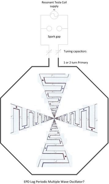
    In all likely-hood one might use a one or two turn spark-gap (resonant) primary coil and enclose Eric's Golden Log Periodic Series Antenna design inside and maybe similar things might be possible?

    Last edited by Sputins; 01-07-2014, 05:07 AM.

    Leave a comment:


  • Sputins
    replied
    Mwo

    Originally posted by Dingus View Post
    I would like to make one of these for a friend of mine who is sick. There are many instructional sites on making PCBs, so that shouldn't pose too much of a problem, but my biggest concern is tuning the primary coil. I understand that the other coils are log periodic following the golden ratio, but that won't mean much if the primary is out of tune, will it? What frequency should the primary coil be? (and I'd have to assume the PCB is rather uniform in its capacitance)

    I should also mention that my friend has a large metal implant. Does anyone know if that or any near-by electronics would cause any complications, or do any harm to the electronics?
    @Dingus
    The Lakhovsky Multiple Wave Oscillator Handbook put out by Borderland Science (Tom Brown) is a good resource to start with. In this book is Eric’s ‘Lakhovsky’ Golden Ratio (Logarithmic) antenna design. There are a number of circuits in that book which Eric drew some not credited to him as such, but they are clearly his, from the hand writing & drawings. Then there is Eric’s updated circuit that John P posted.

    As for the antenna, the first ring is just like a single turn Primary coil on a spark-gap Tesla coil. The thing it was Eric’s idea was to make the antenna in a logarithmic form according to the Golden Ratio. (1.618 or 0.618) (Same idea for the extra coil wire spacing of 62%, an approximation for 0.618)

    So building the antenna on the Golden Ratio formula is likely to be more healing to the body. With luck, if the antenna is in Golden Ratio relation, the complex harmonics is also likely to be Golden Ratio in relation?

    A homemade unit could easily be made, doesn’t have to be powerful, just as long as you have a resonant condition in your Tesla Coil and a spark gap (1B22 would be a bonus) to provide a broad spectrum of frequencies / harmonics, build it according to the Golden Ratio.

    Likely a single turn primary of that size is going to have a very low inductance of just a couple of micro henrys. So if you can determine what your centre frequency is approximately out of your Tesla Coil, design the primary tank circuit around that. Make the resonant parameters approximately fit. If your frequency in the range of 0.5 to 2Mcps and you have say 3 micro henrys of inductance, a resonant tank circuit capacitor will likely be somewhere between a 0.002 and 0.04uF. Use variable capacitors if necessary to seek it out, once found replace with nearest fit, fixed capacitors.

    Yes this device would likely interfere with local electronic devices. Not sure about the metal implant.

    Good luck.
    Last edited by Sputins; 01-07-2014, 04:23 AM.

    Leave a comment:


  • orgonaut314
    replied
    Originally posted by Dingus View Post
    Thank you, but after reading through the website that PDF came from, I don't think I can trust it very much. The template didn't even mention any sizes, so if the DPI of my printer differs from the person who made it, they'd be tuned differently. And it didn't include the strips on backface needed to make the PCB into capacitors. With different size/materal board between the layers there'd be different capacities. Isn't it supposed to basically be an LC circuit? And what's with the overly complicated schematic for the power supply?
    Hi, I think you would have to print the drawing on A4 or A3 as the text says (didn't reread it). As for the power design. Here is the thing. The powerunit is just a spark gap. Eric used spark gaps from diathermy machines, they are something like this one with a Ford bobine.
    The Lakhovsky antenna is in fact the primary from Tesla just like the hairpin was a first primary design by Tesla. Tesla went beyond. But that does not mean the hairpin or the Lakhovsky does not work.
    By the way Lakhovsky's antenne is meant to resonate on a large number of frequencies the sparks start all these frequencys and the harmonics. If you just make a ring with diameter 30 cm you have a right frequency there.
    That site might look like not much but the orgone stuff is pretty impressive. The author used to sell it but made everything free in an attempt to have so much people make these things that they can not be stopped anymore.
    Succes!

    Leave a comment:


  • Farmhand
    replied
    Yeah I found the video but it has some profanity so I dare not link it, though
    there is no need just search "Hilarious Lightning strike". It hit in Ipswich,
    Queensland, nice strike. People need to be wary that the window they watch
    the storms from is not near where the electrical feed comes to the house.

    The guy done well or got lucky to catch the parts he did. Awesome. I bet
    they felt alive after that one.

    I was doing it one day and a bolt hit the pole, then a ball of lightning rolled
    down the lines and dropped onto a passing car made it splutter then rolled off
    and dissipated when it hit the ground in the gutter. It could just as easily
    have rolled down the feeder to the window as the feeder line was above the
    window I was looking out of. My reaction was more severe, I jumped back into
    a wall behind me and being a solid wooden wall I bounced right back off it
    back to the window to see the ball.

    Kinda like this. But not so firey. One I seen was more blue. It moved the same but not far before dropping.
    Fireball on the lines is probably fairly common when serious very electrical storms are around.
    Caught on Tape: Fireball Blazes Across Electrified Power Lines - YouTube

    Ducking for cover is a good reaction.

    On the day I was actually watching multiple bolts hitting the lightning rod on a
    fire observation platform, about 3 clicks away, it was taking repeated hits
    with hardly any noise, I can only guess because it had good conduction to
    ground, it kinda grizzled rather than went bang or crack as the associated
    thunder usually does. I was having a good time at first.

    It kinda sounds like that bolt got fairly low resistance to ground as well. Buku current.

    Thanks for the Screen captures. Spectacular.

    ..
    Last edited by Farmhand; 01-06-2014, 04:54 AM.

    Leave a comment:

Working...
X