Announcement

Collapse
No announcement yet.

Eric Dollard

Collapse
This is a sticky topic.
X
X
 
  • Filter
  • Time
  • Show
Clear All
new posts

  • cyborg
    replied
    Health risks

    Here is a chart from the FCC regarding safe exposure to RF.
    The lower the frequency, the safer it is to your health. The low power levels of experiments here are well within the safe range according to the chart.

    FCC_RF_Safety

    There is also a IEEE paper on the subject that goes into detail and calculations, but I didn't think you would want to wade through all that.

    If you are still concerned about exposure, build a Faraday cage around the experiment. At low end HF, chicken wire will suffice.

    OK, now you have no excuses, back to the bench!

    Leave a comment:


  • Farmhand
    replied
    One thing to remember when experimenting, is that we can strain our neck and
    such things by leaning over he bench for long periods, having a long term neck
    and upper back problem I notice when i experiment too long and in fact I can no
    longer look down at a bench for any real period to do anything much any more.

    I just thought I would mention it as some might not connect the neck strain with
    headaches (they make the head hurt), when it could just be from the act of the
    experimenting and not necessarily the experiment itself.

    Cheers
    Last edited by Farmhand; 12-18-2013, 04:50 AM.

    Leave a comment:


  • dR-Green
    replied
    Originally posted by David G Dawson View Post
    Others need to respond here as to what they feel as after-effects from working near radiating sources - other than electromagnetic - it's different.
    Sometimes a brain pain in the front and generally to one side, but most of the time nothing. I wouldn't really associate this with operating the coil but since it's all experimental I keep it in mind as a possibility. But the frequency of this is probably in the region of 1-5% of the time, certainly not consistent enough to make any conclusions so far other than being a coincidence. But seeing as the human body is a nice conductive mass then who knows.

    Possibly some differences in temperature around the extra coil but can't be certain. Hands tend to detune it and stop any effects that may or may not be there.

    Recommended incandescent bulbs for testing:

    MP1MMW - 1.5 Volt - 0.015 Amp
    #40 - 6.3 Volt - 0.15 Amp
    #42 - 3.2 Volt - 0.35 Amp
    #44 - 6.3 Volt - 0.25 Amp
    #46 - 6.3 Volt - 0.25 Amp
    #327 - 28 Volt - 0.04 Amp

    If the filament resistance is too low then nothing will happen, it will be as if the bulb isn't even there. Resonant frequency is very slightly affected by the presence of a bulb, but generally close enough to "normal" to not need any adjustment to get a glow, from there it's easy to fine tune it.
    Last edited by dR-Green; 12-17-2013, 01:13 AM.

    Leave a comment:


  • David G Dawson
    replied
    Triode Driver MWO

    dr-Green and Sputins,
    Thanks for your responses.
    Yes, have the dual Leds setup and was used on the Hendershot device as a non polarised indicator as this was a flip-flop type of generation, not yet achieved.
    Have a small SWR meter here and may find that also useful.

    cyborg,
    Yes, quite correct and realised after Posting that I needed to take the load resistance into account and for the 6SN7 is about 7,000 ohms.
    Here is where it gets tricky and we need to consider reactance of both L and C and can see an amp meter coming in the Plate circuit as an indicator.
    Have a 1500 pf variable cap in with the fixed 1500 pF and did not see much change with that rotated.
    Yes, we are driving the CSI as a transmitter in an attempt to peak tune the system to measure performace and in particular to measure the half power points and gauge the magnification factor of the Extra Coil and of course, to light lamps at a distance as another indicator.
    Also have the RMR 'Regenerative Magnifying Receiver' (2C22) here which is waiting for testing and should be good for range testing.
    My Extra Coil is different to Erics calculated theory but appears to work and I have my reasons why in previous exchanges.

    Lots of work ahead here I feel as this has not been done before and is only a suggested Driver by Eric and need to now work out the fine details and I started last night by reading my ARRL collections.
    Used the 1N34 pickup head on the secondary and was loud in the headphones and removed the ground lug and all signal disappeared.
    Had a feeling my ground of 6'x4' wire mesh was acting as a receive antenna but not the case but the secondary, by design, probably is as I still hear the local Station in the background.

    Crystal Sets are a bit of an enigma in that most of the designs came out of cities where there was a selection of high powered commercial and national broadcasters at work.
    You only heard from the Country folk on the odd occasion as they were probably limited to one or two stations with some improvement in the dark hours.
    The idea of selecting a design that can power a loudspeaker is simply an indicator to me that it is finely tuned and probably a good basic 'front end' and this is where Moray also began.
    Point here is that we are also using this as a receiver of other 'noise' which can be amplified by an organisation of Vacuum Tubes, again like Moray.

    Today I feel like I am in for a cold and I put this down to the beginning of a detox and this is from being near the CSI while it is radiating from the 6SN7 and an MWO type situation - an active MWO.
    The 'IIC Tubes' device (Iron Inside Copper) gives the same reaction but this is from all of Copper/Iron/Bismuth/Neo Magnets/Crystal Ball and a Mobius Coil, all in and around a long 4' Tube device - a passive MWO.
    Don't think people quite understand this Lakhovsky MWO type effect and this is why Tesla looked into the Health side as he also saw it as an electrical kick start to the Human form and so too George Van Tassel with the Integratron and why Moray sought the Patent only associated with health as they dismissed his energy solution as it was NOT thermionic.

    Feel the Pineal Gland is at work here and this is what has been excited into action and something like the body's computer that needs to be housecleaned where all the detriment can be garbage binned - just an analogy.
    Perhaps we already have our own mini Integratron courtesy of Eric Dollard?
    Want to feel enlightened, just build a Dollard CSI and power it up!
    Lots of indicators here and all meaning lots of work ahead for the electrical experimenter.
    Others need to respond here as to what they feel as after-effects from working near radiating sources - other than electromagnetic - it's different.

    Smokey

    Leave a comment:


  • Sputins
    replied
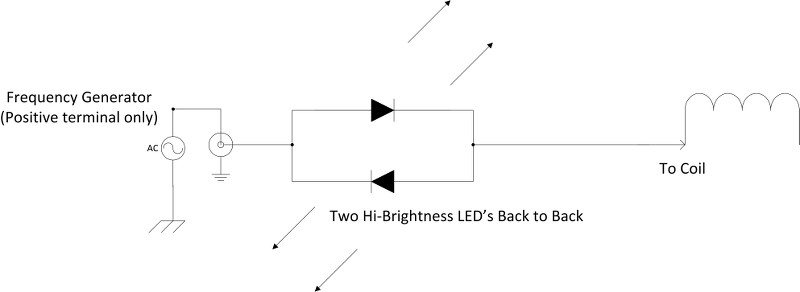
    Simple LED resonant frequency (TEM) test for coils.

    Obviously the most accurate way of finding the resonant frequency(s) of a coil is to use a frequency generator and an oscilloscope. There is another simple (not-quite as accurate) but it’s a very easy and visual method.

    The circuit below is simply two hi-brightness LED’s connected, (soldered) back to back. One end goes to the signal generator (of sufficient output over the forward voltage of the LED’s), the other end, or test lead goes to the coil under test. Once resonance is achieved BOTH LED’s light up. Tune for maximum brightness of the LED’s and then you have found the resonant frequency (TEM) of the coil.


    Testing my spiral coils I found I achieved resonance at 2.08Mcps, (also confirmed with O-scope) As a secondary resonance check I find that my touch lamp several meters away begins to go nuts and cycles madly (strobes) once resonance is precisely found. Hehe

    Anyway if you haven’t seen this little LED resonance indicator circuit, it’s well worth the few cents to put it together. One can even go fancy and include it in a little box and add BNC connectors & a clip if you want.

    Sputins.

    Leave a comment:


  • dR-Green
    replied
    Originally posted by David G Dawson View Post
    dR-Green,
    Went back through the pages to 40 here but could not find your Driver.
    What are you currently using to light your lamps?
    You mean in the latest pictures? A basic op amp as the output stage. The little black dot in the middle of the green board. The other part is for modulating the signal.


    Tuning has to be quite precise in order to light the filament, it's easy to sweep (frequency) about and not notice anything. This should become easier with more power but then the type of bulb is also an issue, because some light easier than others. They are generally connected like this.

    Leave a comment:


  • cyborg
    replied
    lighting the light.

    Originally posted by David G Dawson View Post
    Triode Driver:
    6SN7GTA Triode Driver in parallel works well first up and loud in the headphones.
    Has extended reception distance out to about 5' but no lamps lighting and can even still hear the local Radio Station in the background.
    Went back into Eric's information and come out somewhat overwhelmed by all that he has presented and need to sit back and further digest.
    Using Eric's 110volt HT but notice the specs say 90 volts for 1st Triode and 250 volts for the 2nd and remember him saying he did not have the specs and was working from memory.
    Wondering whether the 110 can't be extended somewhat and not sure why the volts are staggered as a Class A1 amplifier.
    In a TV, both the horizontal and vertical deflection oscillatores are specced at 450 maximum volts and would expect in practice, this would be down graded to about 300 to 400.
    Tuning of the the Function Generator showed the frequency to be very close to secondary design which was encouraging.

    dR-Green,
    Went back through the pages to 40 here but could not find your Driver.
    What are you currently using to light your lamps?
    Thanks.

    Will go back to some basic earlier tests and refine my system as I need to review what I am doing.

    Smokey
    What are you driving, a TC?
    Are you attempting to transmit power to another TC?

    If so, impedance match is important to get maximum power into the primary,, then the coupling to the secondary/extra coil is also critical. If you are using the spiral setup with the strap primary, I think you may have serious issues in this department. It all has to be tuned as a system.

    Leave a comment:


  • David G Dawson
    replied
    Triode Driver

    Triode Driver:
    6SN7GTA Triode Driver in parallel works well first up and loud in the headphones.
    Has extended reception distance out to about 5' but no lamps lighting and can even still hear the local Radio Station in the background.
    Went back into Eric's information and come out somewhat overwhelmed by all that he has presented and need to sit back and further digest.
    Using Eric's 110volt HT but notice the specs say 90 volts for 1st Triode and 250 volts for the 2nd and remember him saying he did not have the specs and was working from memory.
    Wondering whether the 110 can't be extended somewhat and not sure why the volts are staggered as a Class A1 amplifier.
    In a TV, both the horizontal and vertical deflection oscillatores are specced at 450 maximum volts and would expect in practice, this would be down graded to about 300 to 400.
    Tuning of the the Function Generator showed the frequency to be very close to secondary design which was encouraging.

    dR-Green,
    Went back through the pages to 40 here but could not find your Driver.
    What are you currently using to light your lamps?
    Thanks.

    Will go back to some basic earlier tests and refine my system as I need to review what I am doing.

    Smokey

    Leave a comment:


  • cyborg
    replied
    chrystal set and transistors

    The high power crystal set will probably not be audible through the speaker unless you are in a metro area close to the transmitter. there will be too much loss in the transformer, I would suspect. Ditch the the transformer/speaker and sub it with high impedance headphones or maybe try a very tiny transformer and speaker like what might be used in an old pocket transistor radio.

    Bipolar transistors such as npn, pnp can be readily rested with nothing more than a multimeter with a "diode check" function They will read like "back to back" diodes from the base to collector and base to emitter. You will have to switch the lead polarity depending it's a pnp or npn. The collector to emitter should read open*.

    *some power types have a built-in b-e resistor usually 50-100 ohms, so the b-e wont read like a diode. Some also have a built-in inverse polarity diode across the c-e , but you won't notice that unless you reverse the c-e polarity during the "open" test.

    These tests will tell the story of transistor health for 90% of the cases.
    Of coarse a go/no-go test is no sub for a curve tracer or even a dc gain tester, but you really don't need those things unless you are interesting in the nitty-gritty of the device specs. The data sheet will get you in the ballpark for most applications.

    There is additional protection circuitry that can be built to protect transistors in TC service. The problem is the "experimental" nature of the beast, where there is a good chance that an experiment will cause a sudden change in SWR and impedance which can be very detrimental to solid state devices.
    Tubes don't like it much either but the damage is not quite so obvious so quickly!

    Leave a comment:


  • David G Dawson
    replied
    GLOM CFA NIA Flares

    Just a word on GLOM.
    Old Computer power supply boxes are real good for Tube chassis as well as low DC power supplies - used these originally on the rotating rainmaker machines and their Amp ratings are quite good.
    Old TVs - Flybacks, neck Ferrites plus Copper, both rapidly becoming things of the past and have a huge pile here and was 'told' to collect these items and you also get some high power Horizontal NPN Driver transistors or Tubes like 1S2, 6BK4, 1B3GT etc - Tesla here, high frequency and voltage.
    Yes, my Lab also is chock a block but somewhat organised and causes you to stop at some time and organise better, it's called housekeeping and also 'learn to fix what gets broke'.
    Things above, people are just throwing away and collect on the sidewalk and you go street shopping at collection time - it's free!
    Getting back into my Thyratron downconverter shortly and all of the above is used in those and why I am interested in Eric's help with the Thyratrons - a learning curve.

    Cyborg,
    Good to see the interest in the CFA (Cross Feed Antenna) and thank you for your description on the NIA (Negative Inductance Antenna) as you appear to have a very quick assessing ability and a need to hear more of that here.
    Good luck with your build and one I also have on my project list and will probably also do as well as the NIA.

    Jerry Bales is wrapping magnets around Hydrogen vessels and manipulating the electrons in their orbits and collecting the energy when the electron snaps back into its normal orbit - just a theory at this time but feel more plausible with a Plasma.
    This could be called an 'Oscillatory Chamber' - Philo T Farnsworth type stuff (the concept of this device is in development) but picture this with a Plasma and not electrons and a possible 'Counterspace' interaction where the entire unit runs cool - we need to elevate ourselves above the resistive heat of the electron and go cool and cold with a Plasma which is already being achieved now with the Ion Valve.
    Moray keeps telling me 'its in the Ions'!
    More on this when I get a chance to develop further and not what I would call 'Fission'.
    The reason why I have a large 5C22 Hydrogen Thyratron here for such experiment and also why we see anomalous results with an Impulse Discharge like in a multivibrator device or even a relay - The Tesla Instant.
    I have a cube in the picture with continual lightning inside the vessel and your energy needs are easily tapped off and this is a result of replicating Nature's way of doing things and the entire unit runs cool to cold and exactly what you get during a Thunderstorm - a massive drop in temperature.
    We need to keep in mind that Tesla saw thermionics (filaments) as not what was required as this was the electron activator and not what we should be using and here we have all these evacuated vessels and some with gases and nobody bothers to experiment with them outside of the intended thermionic side.
    Suprises ahead!

    dR-Green,
    Thankyou for the Solar Flare URL.
    Have a status here on my desktop which is showing 'Active' at this time but the Solar pictures don't appear to be telling you too much as I have some difficulty in relating to what is being presented.
    Think the development of the CRD is important at this time as Eric has the ability to understand what is ahead for us all and a need now to monitor the severity of the event or at least to be alert to the changes now taking place.
    The URL and video on Planet X is not to scare everyone, just a heads up and a be prepared for what is ahead for us all.

    I see the 'Negative Inductance Antenna' as another 'Cosmic Ray Detector' but here we have the stand alone principle where we only need an outdoor antenna and NO energy source is required.
    This could be amplified through the twin 1N34 probe head into a speaker and here comes my second Crystal Set schematic which I have already presented here:

    High Power Crystal Set, August 1960 Popular Electronics - RF Cafe

    First one was a dud and have a 3rd option waiting in the wings.
    My association with transistors is to use them where there is no requirement for an outside energy source which is a major problem with the Tubes where considerable sized power supplies and Mains demand is required.
    Don't believe this was a problem with Moray as he was not using external energy sources but managed to manipulate the voltage gains in the Tubes by other organisational means and also what I too am seeking.
    What Eric is doing with the CIG, I don't think you would even contemplate using solid state (SS) as your specifications would always be way above what was available.
    With Tubes for an experimenter you get a warning of trouble and not so with SS, just an instant death!
    Can you take your transistor out of the circuit easily and place it on a Tester like you can a Vacuum Tube?
    With the UK Telequipment (UK Tektronix) yes, you could but this was an interim measure and a bit like the Nuvistor but was soon phased out and became a permanent solder job.
    Thus began 'the throw away society'!

    Smokey

    Leave a comment:


  • cyborg
    replied
    orginal CFA patent

    Here is a pdf of the CFA patent. It's an outline at best.
    I read discussion that there may not be sufficient capacitance to produce enough displacement current to aid in strong field generation. Some quick calculations seem to verify that assertion, unless the device was driven at very high voltages.

    However, the patent implies that the CFA can be driven with the power splitter described in the papers by a standard 50 ohm transmitter. no mention of high voltage RF at all.

    I have a couple of disks now, so maybe i'll make the cylinders from mesh screening.
    The "dipole version" with dual plates and cylinders has best chance of success, IMO.
    Attached Files

    Leave a comment:


  • cyborg
    replied
    negative inductance antenna

    The negative inductance antenna is not all that mysterious.
    Basically it's a trick that NEGATES the phase of the inductance.
    A capacitance is a negative reactance that varies inversely with f.
    A negative inductance is a negative reactance that is directly proportional to f.
    So, if the phase is kept at zero the antenna is broadbanded by being resistive
    over a wide spread of frequencies without a LC resonance characteristic.

    Other other hand, the CFA is sort of fractal antenna that works by combining the Fields in such a way to produce a third.
    It's very small, 1/200 of a wavelength, so it world be great for applications where more conventional antennas are too large...if it works on transmit AND receive...

    I'm going to scrounge up some stuff now...

    Leave a comment:


  • dR-Green
    replied
    Smokey, thanks for the tips on inserting or removing the valves/tubes. Also good idea with the "L" brackets. The only metal boxes I have are computer cases, in fact I seem to have become a magnet for old computers and monitors lately, there's literally no room to turn around in the lab except for a small corner which has been kept clear to finish off the tests on the new coils. Now that those are done I will need to do major work on getting a bench in there and sorting everything out.

    Anyway, on the weather, the last time I spoke to Eric he told me to check this out Solar Flare Alerts | About Solar Flares | Warnings | Solar Flare Storms - FlareAware.com If I remember correctly he said it's all about to go crazy. I think he'd recommend heading for the bushes...

    Leave a comment:


  • David G Dawson
    replied
    Negative Inductor Antenna

    Wrote a little earlier on this but here is the real data on the Negative Inductance Antenna - NO CAPACITOR and no tuning.
    Quote:
    "the antenna becomes broadband and the necessity of tuning the antenna to an individual frequency is obviated".

    Feel this is an extension to the TMT and is what the CFA is bordering on as nobody appears to know how these Antennas work and would suggest a counterspace and LMD component and much as to what we are all currently working with.

    Two US Patents are involved from a Thomas K Albee on a 'Broadband VLF Loop Antenna System':

    Broadband VLF loop antenna system - The Bunker Ramo Corporation

    'Submarine Antenna Communications System' (3 to 300 khz):

    SUBMARINE COMMUNICATIONS ANTENNA SYSTEM

    Note this is all VLF and also in the lower area of our investigations and could probably be extended into the 1.8 ~ 2 Mhz band.
    When you look at the Figs 3 & 4 of the second and you see more than a 10x amplification factor in both volts and 'Q' you must realise you are on to something.
    Will be building this, the first gives component values but not the transistor types and would be suggesting Germanium but then again, this is open to experimentation just like the back to back transistors to emulate a 'Tunnel Diode'.
    2N2222 is always a good general Transistor for these types of projects.
    I firmly believe there are considerable extension today to the work of Tesla and this is one of them and is still not understood what is manifesting.
    Still searching for more to the Moray 'front end' where no external source power is being utilised.

    Smokey

    Leave a comment:


  • David G Dawson
    replied
    Planet X

    Planet X, A Brown Dwarf, Second Sun, BlueBonnet:
    Knew this would eventually come out with some better insights as to what is about to happen:

    Planet X/"Nibiru"/Brown Dwarf Twin Planet X System Observations and Orbital Analysis

    Had to blame the erratic Weather on something and what better than Planet X.
    Like the man I talked to the other day who said the Weather was not normal and most irregular and could only agree.
    This may be the reason why the Sun is quiet and the other influence in our skies is taking hold but as yet we cannot see its surface or even know how active it really is.
    I keep saying that I don't see a connection between the Sun and current severe Weather like another named Blizzard for the US and an Atlantic Storm about to hit the UK and Europe and the sheer intensity of Haiyan rolling through the Phillipines.
    Would very much like to know how Piers Corbyn (UK) is predicting the Weather as I doubt it is from the Sun but is probably from a Cosmic Ray Detector (CRD) and this may be why Eric Dollard is interested in such and you will also note that he states the exact same in one of his videos that the Sun has gone quiet and is 'dying' - might be a little more to it than just that.
    Jupiter, as our current second Sun could also be changing its energy patterns.

    Smokey
    Last edited by David G Dawson; 12-14-2013, 05:32 AM. Reason: spelling

    Leave a comment:

Working...
X