Breadboard builds
Everybody's breadboards are looking good. Having output is even better!
I think I'm going to build one of those intriguing looking CFAs.
If it works, I have some applications to try it out on.
I wonder if it receives as well as it is supposed to transmit? Since this spec has been glossed over, I suspect the receiving results may not be as stellar.
They are simple enough to make, though!
Announcement
Collapse
No announcement yet.
Eric Dollard
Collapse
This is a sticky topic.
X
X
-
Sputins,
Excellent work!
A good feeling when it all comes together - you don't get that feeling with solid state - no glow!
Dewey Larson has explained very well our involvement with technology where nobody is really interested and just want to go along with the flow - Adam Bull has expressed the same disallusionment with people and society who seem to be fixed in a state of being on the Planet but not being a part of it.
They simply don't want to know and this can only be called a part of the sheeple program - its working!
Am collecting parts here for the Tektronix Oscilloscopes (mine is a 564B & RM503) but having difficulty sourcing the Compactrons - Nuvistors are OK.
dR-Green,
Yes, you may be correct in that I am too close to the coil and will set up for the new test as that was my intention and why I Posted and appreciate your observations.
And again the TTPG is for the CIG but will test it on the CSI without the cap, just for interest.
Thanks for the offer with respect to detail to Eric but had a letter to him also in mind and will do so as that way I do get some direct answers and will give him a Christmas present as well.
I think he enjoys responding to letters as he can include some of his invective in those about all that he does and doesn't like and makes for interesting reading.
Will be including detail on a 'Negative Inductance' ( NO Capacitor) antenna which I will Post here shortly and think he should consider this with respect to long line antennas.
Horrors of all horrors it includes two transistors but these are Moray transistors and they use no external power and feel this is an answer to some of the antenna problems we need to dig deeper with.
This may also be able to be used with Vacuum Tubes and will be building as it just sounds to be too good to be true and feel a sychronicity here with the TMT/CSI.
CRI - Crystal Radio Initiative
CSI - Crystal Set Initiative
TMT - Tesla Magnifying Transmitter
FTL - Faster Than Light

Uploaded with ImageShack.us
Have finished building the 6SN7 'Triode Driver' in parallel mode and will now try that on the CSI - this will be the 5th Dollard device.
(Eric P. Dollard Page 14 Post #399)
Used two 6" long x 1" x 1/2" aluminium angle and placed the valve bases across those with two bolts low on the frame for rigidity and works well.
Used two bases, 1 for the Triode Buffer if required or something else and those are the parts required at top right.
The 'L' angle is good as you can fit a pot if needed on the sides but looking at going to a 2" x 1/2" and this will give much greater depth for components.
Always a problem obtaining a chassis but this is an easy way out and no large holes required to be cut out and air conditioning is great.
When I insert new Valves into bases I always use a petroleum jelly smear on the pins as this frees up the workings after being idle for so long and makes insertion and removal that much easier.
The RCA box is home built - any Tube that I know I will be using has a box made up as they nearly always come unboxed - easier to stack and safe to handle.
The four and five and even the 7 pin bases used for the multivibrators are of the 'grab' style, easy in, hard out but the Octals are 'pressure' style and just need the lubrication.
Another pic showing some of the Tag Strips available for Vacuum Tubes:

Uploaded with ImageShack.us
Just noticed I have an error on the board which needs to be corrected before power up.
GLOM:
Have managed to buy more 6AG7s (Power Output Pentode) in military guise of the metal can type but there is always a catch and comes with a heap of 6AC7s (sco RF Pentode) but may be a good candidate for Moray.
This sco, mco and rco means short, medium, and remote/long cutoff and gives you some idea if you want fast or slow.
Typical example is not using an rco where you have AGC or similar involved.
Smokey
Leave a comment:
-
Sputins, it's beautiful, looks really nice to me, I know very little about
tubes/valves, but the scope tells the story, lovely wave form. I wish my health
would allow me to do more work and study, but thems the breaks.
Can I ask what voltage would you be expecting to get from the Tesla
transformers when driven by this ?
Cheers
Leave a comment:
-
I have 2-4 more tests to do on the new coils and then I'll be sending Eric some mail. If you want I can print out your CRD posts and put them in the envelope if you haven't made other arrangements.Originally posted by David G Dawson View PostEric P Dollard:
If this is your official blog site - it would be really nice if you could come in now and again and answer our questions as I see them all being ignored.
I know you hate this medium but what recourse do we have left - snail mail?
Leave a comment:
-
Very nice work there Sputins!
Did you tune both receivers with a local oscillator to make sure they are in phase before starting? Also keep the overground antenna a decent distance from the TMT otherwise you'll just be picking up the signal from that. If everything in the area is saturated then you might have a problem.Originally posted by David G Dawson View PostDid some comparison tests between the Hertzian and Telluric propogation and was disappointed in that I saw no discrepancy
Slow but adequate. The periods in between is where you should do your homework.Originally posted by cyborg View PostThis is a slow way to get from A to B on many levels, sort of like turning on your favorite TV channel to watch the test pattern!
Leave a comment:
-
EPD Channel?
This is a slow way to get from A to B on many levels, sort of like turning on your favorite TV channel to watch the test pattern!I'm guessing he doesn't have a clue that any of this is happening right now because he doesn't have the internet, or even a computer. The only way he can know is if someone calls him up or writes a letter to tell him.
Leave a comment:
-
Questions needing Answers
Why are we working with Eric P Dollard material and devices?
Mine is a simple quest for 'Energy Synthesis' (ES) and probably all of the others will also agree and also to learn more about Tesla from the Master and with an eventual replacement for 'alternative electricity' that we don't have to pay for.
Would like to ask Eric about Carbon and what he knows of its ES ability as it was noted by Tesla as being the doorway to the 'Warmth Ether'.
I keep collecting the stuff here and a good source is the old Movie Projector rods made from Carbon/Copper sleeve.
Thinking of following dR-Green and Sputins, think Madhatter and Geometric Algebra were also moving along this line and going into a full blown CIG but using Carbon Anodes as in the original RCA 805, 813 type of Tube.
Would very much like to prove my Extra Coil theory but would like a profound response from Eric as to where the CIG is going to lead us.
Seeking direction here from the Professor to assist us in knowing what is possible in the future by following his lead.
It is not only the Quadrature learning curve we are involved with here but also the carrot at the end of the stick - where are you leading us?
Did some comparison tests between the Hertzian and Telluric propogation and was disappointed in that I saw no discrepancy and appear to be in an area where the EM signal is being dumped here into this locality by antenna design - Dipole.
This is supported by the simple 1N34 dual probe being used to easily pick the signal off the wire fenceline of the property.
Was going to install a 27' Alexanderson antenna but at the point here where we are looking at downsizing and now looking at something smaller that is capable of being transported easily and here we need to look at the Alexanderson system and see if that is not at all possible and can Eric assist in that area?
The Cross Field Antenna may be such an answer:
Crossed-Field AM Radio Transmission Antenna - 1/50 Wavelength Long; 100 kW
There is now considerable detail on the Inet on this antenna and would like to suggest that there are possible sychronicities with the Alexanderson system.
I know you are out there in the desert paddocks fiddling with the idle long line telephone systems but can't that be downsized into a convenient 10' cube or similar?
Talk of counter spatial or reactive elements and utilising both the distributed networks of Tesla and the lumped networks of Alexanderson - surely all of this cannot be reduced into a cube like the size of the CFA?
Nobody appears to understand how the CFA works and suggests strongly an association with both the distributed and lumped components and where the LMD and counterspace is very much involved like the Camp David and the Log Periodic Antenna.
The sole idea of utilising the 'counterspace' is working within a small area - the long line stuff can be achieved within the cube in 'counterspace'.
Am I making sense here?
Perhaps we are in need of a Fractal Antenna?
Tesla did part of it in a simple extended coil and now the Alexanderson 'counterspace' bit needs to be added in a convenient cube size.
As I see it.
Smokey
Leave a comment:
-
6AG7 / 807 Vacuum Tube CW Transmitter
6AG7 / 807 Vacuum Tube CW Transmitter & Power Supply: Virtually completed. Various controls for the Oscillator tune & key, Dip meter for fine adjustment, PA Plate current & PA key, indicator bulb for filament power. The power supply has a voltmeter to 1000V and 300mA meter for the main plate supply. The power supply contains the main transformer (via a Variac), filament transformer, negative lead chokes, FW rectifier and the filter caps. The Transmitter is exclusively driven via the VFO, no crystals.
Test Setup: The 30Watt light bulb being the dummy load on the transmitter via the LC tuned & impedance matching pi- network. The pi network is experimental, the dip in the mA meter can be found easily. The light bulb is far brighter than what appears in the picture! Light bulb running on 2Mcps.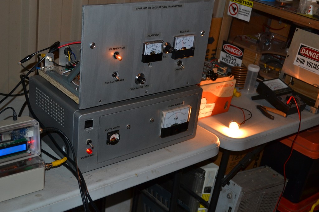
Pi Network: Experimental, temporary setup, next to experiment with driving an actual primary coil.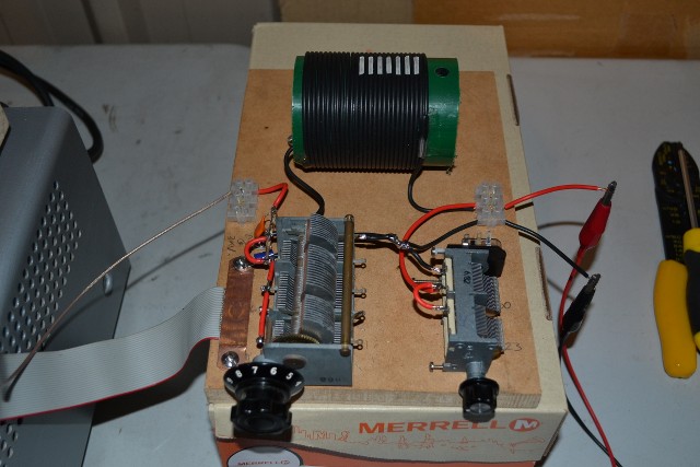
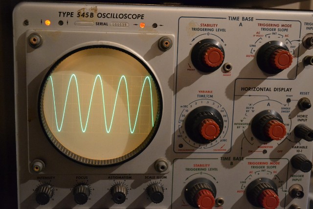
Oscilloscope Tektronix 545B: The output of the 6AG7 seen here, 30Vptp @ 2,000,000cps. I think with another new plug in L1 coil (or smaller variable air capacitor) I can improve slightly on that output.
Transmitter: Rear view: Filament, HV’s (+750, +300) & VFO in at rear, (cannot be plugged in wrongly). 6AG7 tube and L1 plug-in oscillator coils for the 160, 80 & 40 metre bands. Power Amplifier finals are two parallel 807 tubes.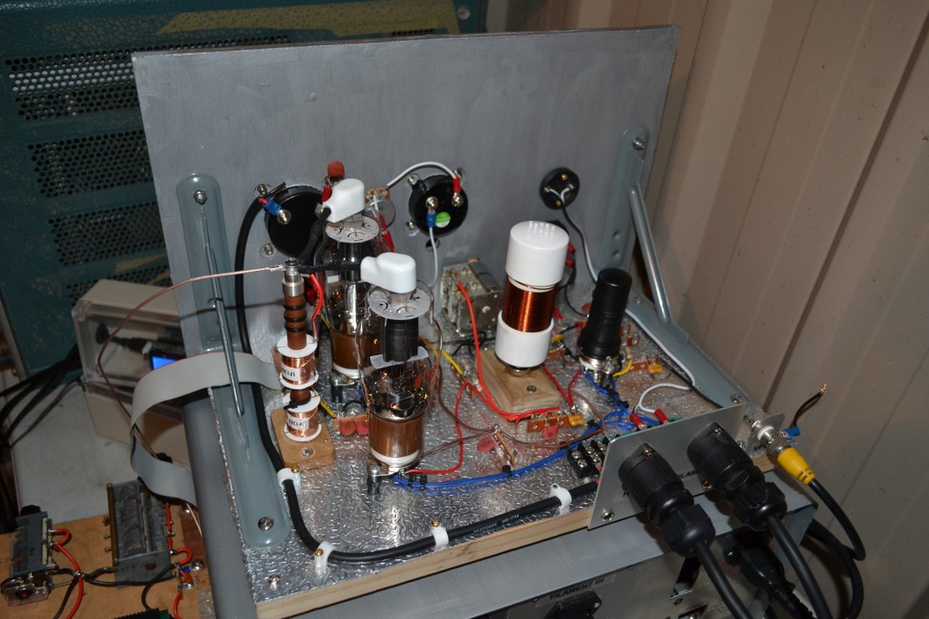
Transmitter 807 tubes: In parallel for near 100watts. The next version transmitter will have these in push-pull arrangement. Perhaps two 807’s each phase, four 807’s in total.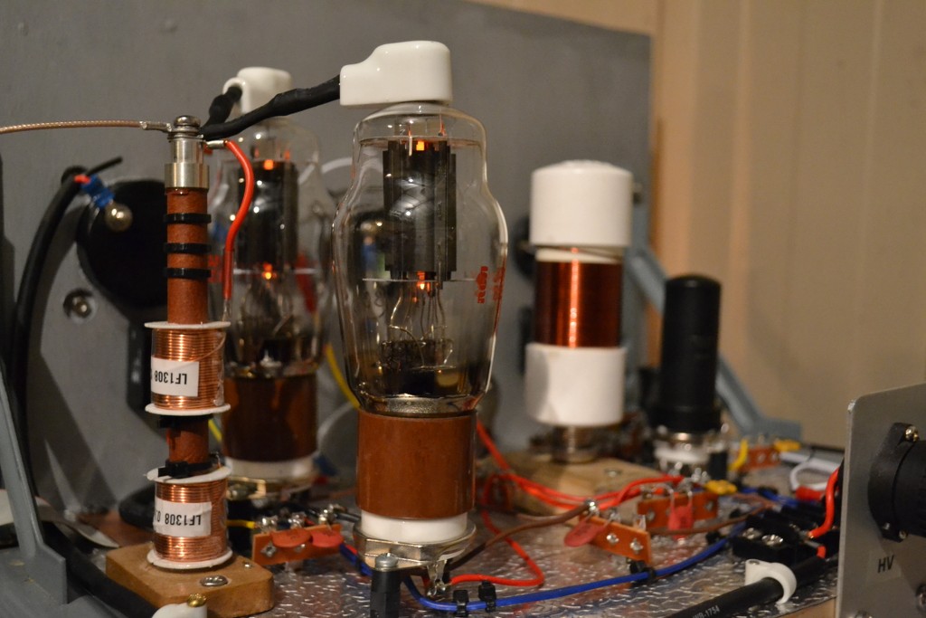
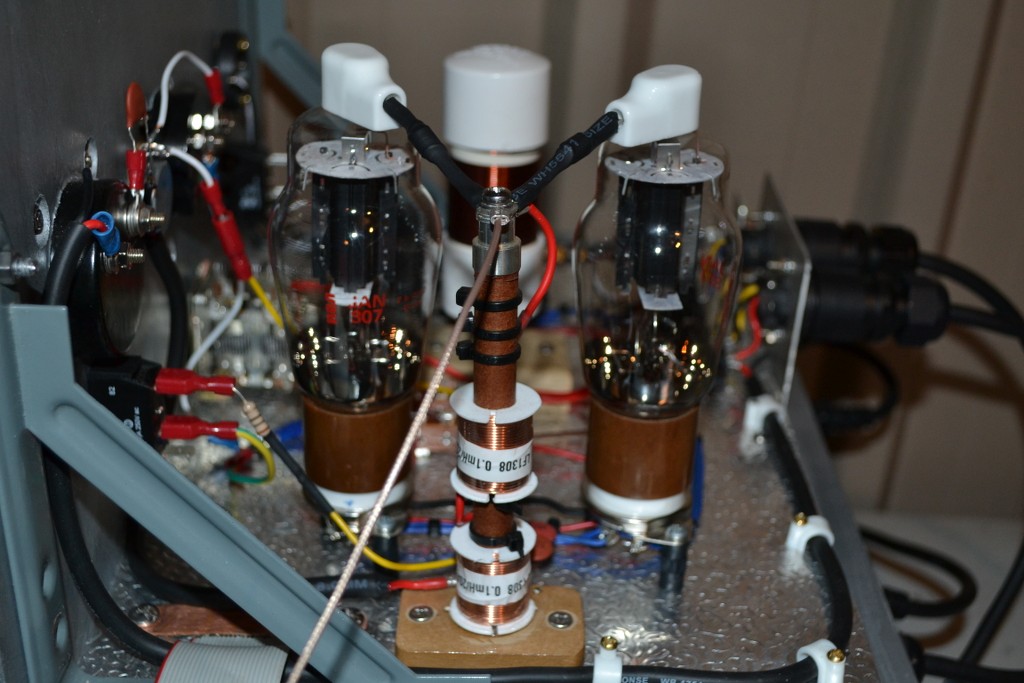
There it is. My first transmitter build, far from perfect but has been an invaluable learning exercise into the world of vacuum tubes and CW transmitters. The Transmitter is only for use with driving TMT coils and CIG (no antenna system). So now that I have a 100watt vacuum tube variable frequency driver from 0.5 to 5Mcps, I can now return my efforts back into the CIG coils themselves. The primary coil(s) are my next main focus. Also the CRD as a side project.
Sputins.Last edited by Sputins; 12-12-2013, 01:19 AM.
Leave a comment:
-
@Arto: Wonderful articulated words with your last post. Just simply brilliant! I totally agree.
@Smokey: True experimental research! 100%! (What the-heck do ‘normal people’ say & think when they come to visit you with those strange Orgone weather modifying devices spinning around and the various devices around your lab)??! Har-har. Great to see!
Leave a comment:
-
As far as I know the 2050 is to be used for driving a CIG type setup, the 6SN7 is for driving the CRI coil for some higher power testing than an oscillator can do alone, to be able to use neon bulbs and fluorescents to see the gradient along the coils etc. But that should be pretty good for low(ish) power transmissions too.
I'm guessing he doesn't have a clue that any of this is happening right now because he doesn't have the internet, or even a computer. The only way he can know is if someone calls him up or writes a letter to tell him.Originally posted by David G Dawson View PostIf this is your official blog site - it would be really nice if you could come in now and again and answer our questions as I see them all being ignored.
Leave a comment:
-
Tesla Transformer Pulse Generator
TTPG:
Spent part of the day looking at the NET pulse of the pulser and don't like what I see - a really spikey negative pulse and cannot see why.
In reality I don't know what frequency I should be using but have settled on 250 hertz and the same initially for the test HT voltage.
2050 is working well and all appears to be normal and Eric's schematic is of a basic pulser but for such a circuit as the CSI?
Radar stuff here and limited in frequency to about 2000 cps but do I remove the cap in the primary and just pulse into the Copper - will have to remove to find out?
'The Electrical Experimenter' is right but leads into 'Bog Down Constructions' and we are really not sure how we should be doing any of this.
Have been through the notes but Eric does not elaborate too much as he covers just so much ground.
Looks like I need to build the 6SN7GT pulser instead and this can be made a parallel line for more grunt and can then use the designed frequency of 1557 khz.
In review I feel the TTPG was an example of a thyratron pulser using the 2050 but would not be a candidate for the CSI.
Anyway we have another build of Erics that works and will do the 6SN7 pulser as we now have all the support equipment for Tubes as well.
GLOM:
Picked up a Range Calibrator BC-949-A (Korean War) cheaply on Ebay and has a 6H6 power supply and what I would expect to be a 6SN7 as it is a small transmitter and really wanted a housing for more Tube projects - should work well for the above and can add others to the same chassis.
Eric P Dollard:
If this is your official blog site - it would be really nice if you could come in now and again and answer our questions as I see them all being ignored.
Not much good putting up projects for us to do if you are not going to assist in the construction so that we have a successful conclusion that helps to support and also verify your own theories.
The occasional kick in the butt is all we need and we might gets things rolling a little faster.
I know you hate this medium but what recourse do we have left - snail mail?
Thanks.
Smokey
Leave a comment:
-
****correction****
Ok Doc, wow, I messed up by an order of magnitude!! It needs a re-do as follows:Originally posted by cyborg View PostOk here's where little errors creep in:
8.28 cm = .828 meter
length per turn = approx .828 meter X pi = 26.012
126 X 26.012 = 327.76 not 32.271 meters
This must just be a slip of a decimal because you do get in the correct ballpark in the end.
full wave = 300/327.76 = .9153 MHZ
quarter wave = .9125/4 = .228825 MHZ or 2288.25 KHZ
We already slightly disagree on the initial numbers.
You also note significant differences according to the the test method being used. Obviously the coil is being influenced by the coupling. Maybe even the counter pickup?
When I get a chance I may attempt to make one of these and do my own test. What was the spacing and guage?
I get 32.77 meters length
full wave = 300/32.77 = 9.153 MHZ
Quarter wave resonant at 2.28 MHZ for a straight wire.
Like I said, everyone can make a mistake...EVEN ME !!!

Leave a comment:
-
You mean 0.0828Originally posted by cyborg View PostOk here's where little errors creep in:
8.28 cm = .828 meter
length per turn = approx .828 meter X pi = 26.012
I assure you the circumference of my coil isn't 26 metres!
That's because you use 300 and I use 299792458.Originally posted by cyborg View PostWe already slightly disagree on the initial numbers.
[edit] I see what you mean. I think the calculations were done in a spreadsheet so the rounded up or down numbers don't necessarily end up translated 100% accurately to the forum in text, and the coil was built from the wire length rather than the wire length being calculated from the circumference. 8.28cm diameter is "calculated" but of course building the thing to that level of accuracy by hand is impossible. The pre-cut wire length fitted the coil frame perfectly. The other two configurations on the same frame are probably calculated from the circumference and the physical wire length was cut at a certain number of turns physically wound on the frame. The first one was not done this way because I already knew the length.
The noted differences (between coils) are due to lack of knowledge/experience with the first coil and first set of test. Through all that I learned to how optimise the test setup, and as you can see in the two next coils I'm getting both around the same propagation. This is mainly due to nearby objects and the pickup for the probe etc, if it gets too close then it lowers the frequency. Also any differences in the wire length leading from the oscillator to the coil has an effect.
The wire gauge doesn't really make much of a difference but I think it was 24 SWG. Conductor spacing should ideally be 62% if you're going to do a proper job of it.
Originally posted by cyborg View PostYou also note significant differences according to the the test method being used. Obviously the coil is being influenced by the coupling. Maybe even the counter pickup?
Measurements:
2.5pF = 4030 kc
5pF = 3964 kc
10pF = 3887 kc
25pF = 3786 kc
50pF = 3737.5 kcLast edited by dR-Green; 12-11-2013, 12:00 AM.
Leave a comment:
-
Ok here's where little errors creep in:Originally posted by dR-Green View PostThat is not my result, it's Tesla's. Eric verified it back in the 80's. I have done it on numerous occasions and with different coils. Farmhand posted that his extra coil shows the same thing on the previous page. Even the online Tesla coil calculator incorporates it. Someone else did some sort of a study and report on it, but I don't know the URL for that.
Extra Coil:
126 turns
Diameter = 8.28cm
Height = 8.28cm
Conductor length = 32.271 metres
Luminal frequency = 2322.4 kc
Direct = 2694.8 kc = 116%
10pF = 2833.1 kc = 122%
New Extra Coil #2:
97.25 Turns
Diameter = 8.28cm
Height = 8.28cm
Conductor length = 25.323 metres
Luminal Frequency = 2959.677 kc
Direct = 3522 kc = 119%
10pF = 3831 kc = 129%
New extra coil #3:
93.25 Turns
Diameter = 8.28cm
Height = 8.28cm
Conductor length = 24.256 Metres
Luminal frequency = 3089.819 kc
Direct = 3676.7 kc = 118.99%
10pF = 3990.5 kc = 129.14%
Note that the design frequency in this case was 3670 kc. For "New extra coil #3" the calculated quarter wave wire length was multiplied by 1.19, resulting in direct connection measured frequency of 3676.7 kc. The wire was EXTENDED to bring the frequency DOWN to the intended value.
How can you disagree and dispute it when you don't know?
The new Colorado Springs scale model extra coils also show the same thing, but I won't be posting details on that.
8.28 cm = .828 meter
length per turn = approx .828 meter X pi = 26.012
126 X 26.012 = 327.76 not 32.271 meters
This must just be a slip of a decimal because you do get in the correct ballpark in the end.
full wave = 300/327.76 = .9153 MHZ
quarter wave = .9125/4 = .228825 MHZ or 2288.25 KHZ
We already slightly disagree on the initial numbers.
You also note significant differences according to the the test method being used. Obviously the coil is being influenced by the coupling. Maybe even the counter pickup?
When I get a chance I may attempt to make one of these and do my own test. What was the spacing and guage?
Leave a comment:
-
That is not my result, it's Tesla's. Eric verified it back in the 80's. I have done it on numerous occasions and with different coils. Farmhand posted that his extra coil shows the same thing on the previous page. Even the online Tesla coil calculator incorporates it. Someone else did some sort of a study and report on it, but I don't know the URL for that.Originally posted by cyborg View PostThe proof of the pudding in any experimental result is repeatability. Has anyone independently verified your result?
Extra Coil:
126 turns
Diameter = 8.28cm
Height = 8.28cm
Conductor length = 32.271 metres
Luminal frequency = 2322.4 kc
Direct = 2694.8 kc = 116%
10pF = 2833.1 kc = 122%
New Extra Coil #2:
97.25 Turns
Diameter = 8.28cm
Height = 8.28cm
Conductor length = 25.323 metres
Luminal Frequency = 2959.677 kc
Direct = 3522 kc = 119%
10pF = 3831 kc = 129%
New extra coil #3:
93.25 Turns
Diameter = 8.28cm
Height = 8.28cm
Conductor length = 24.256 Metres
Luminal frequency = 3089.819 kc
Direct = 3676.7 kc = 118.99%
10pF = 3990.5 kc = 129.14%
Note that the design frequency in this case was 3670 kc. For "New extra coil #3" the calculated quarter wave wire length was multiplied by 1.19, resulting in direct connection measured frequency of 3676.7 kc. The wire was EXTENDED to bring the frequency DOWN to the intended value.
How can you disagree and dispute it when you don't know?
The new Colorado Springs scale model extra coils also show the same thing, but I won't be posting details on that.Last edited by dR-Green; 12-10-2013, 07:11 PM.
Leave a comment:
Leave a comment: