Announcement

Collapse
No announcement yet.

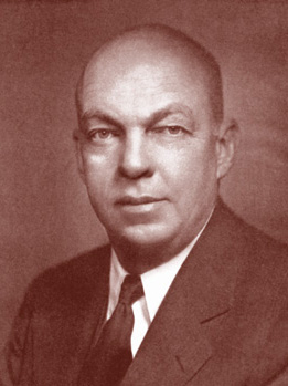
Eric Dollard

Collapse
This is a sticky topic.
X
X
 
  • Filter
  • Time
  • Show
Clear All
new posts

  • Sputins
    replied
    Originally posted by cyborg View Post
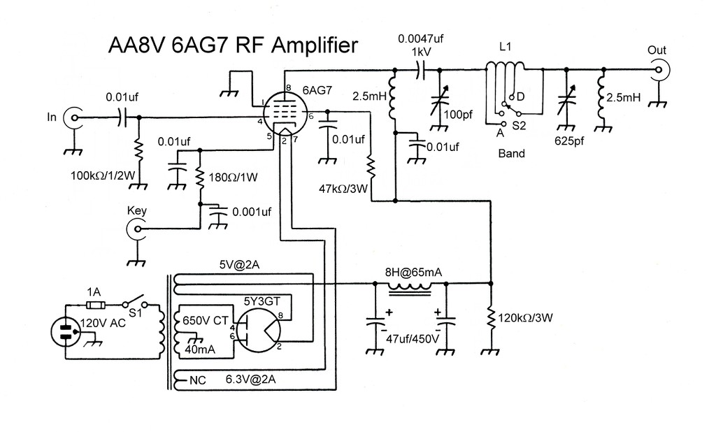
    The Tube circuit is indeed a low power amp designed to take rf in and supply power to an antenna . The plate circuit contains a classic "pi network" for that purpose. The output is controlled by the key (CW transmitter)

    I have already built high powered solid state Tesla stuff. They work fine. In fact they have features not found in the tube versions.
    I'm not Eric Dollard, so what do I know?
    A lot has happened since Tesla's time so why not avail ourselves of the advantages?
    Okay yes correct, the posted schematic is for a low powered CW amp with a pi network for an antenna. My purpose is to simply use the 6AG7 as a pre-amp to drive the grids of larger, higher power tubes. The provided links talk about using a low power VFO into a 6AG7 to drive the grids of a 6146B tube.

    At work we have many analytical RF plasma instruments that run constantly 24/7. The older ones use 3CX1500D3 tubes (that contain beryllium however) but are very robust. Rarely a tube dies and a replacement is easily installed. The later model instruments use special HV transistors with water cooled heat sinks. It is found that the transistorised models fail more often (quite often) and the replacement HV transistorised module is more expensive and harder install than a tube.

    Nevertheless if you want to produce a transistorised driver using MOSFETS, or other HV transistors with the added features then no-one is stopping you. Perhaps you could even share your schematic and experiments. It will most likely be quite popular with some people.

    However my intent is to learn about and apply the lost & dying art of vacuum tube technology with regard to ham radio, the CIG & TMT drivers as per the instruction / suggestion of Eric (and others) because that is what Eric is an expert with, it works & is proven by experiment.

    Leave a comment:


  • David G Dawson
    replied
    Responses

    orgonaut314:
    Thankyou for your comments.
    The cap covers about 1" and the Primaryy was designed to have a 6" overlap of the two turns to fit the cap into.
    Cap is 6x ruffled aluminium plates with polythene damp proof course as the insulator and fills the 1" gap nicely with about 1500pF and the 3 gang variable gives another 1400pF to play with and has solid white nylon outers to keep everything in place.
    Designed ahead with this as I knew I would have to fit a cap in somewhere and securely at that and the overlap gave the required space.
    All in accord with what Eric describes in his notes and I was fortunate in having messed in this area previously with a Don Smith device.
    Will take a close-up of the detail and show the Smith version as well.

    cyborg:
    Yes, thanks was aware of that and why I am making up a test bed to find the best solution to the problem but needed to also improve my understanding of Thyratrons, the 2050 in this case with the second shield grid.
    Have worked with the OA4G on the CRD and also have a test bed for that which helped in the understanding.
    Began working on Thyratrons about a year ago as I had a device that was able to charge oil-filled caps rapidly from a flyback, spark gap, bridge rectifier arrangement and discovered that I didn't need a spark but just a plasma event like in an Ion Valve and this I am slowly getting back to.
    The problem was downconversion to useable energy from the caps and the solution to that was using Thyratrons and probably directly through a transformer to give the required AC.
    Hints of OU here as the supply drain dropped to near zero but the caps continued to charge.
    I think if I had been working with Philo T Farnsworth, I would also be sticking to Vacuum Tubes as you are just that much closer to the Plasma events which is one off the Aether and you can remove or sidestep the electrons that are only getting in the way causing heat and resistance as you have so many grids to play with.
    Don't think you can do that successfully with solid state as you require a void of space of vacuum or gas and this is the key as the Aether just loves a vacuum, denied in solid-state.
    I build the test bed models as they may also assist with the TH Moray efforts.

    Smokey
    Last edited by David G Dawson; 12-04-2013, 01:05 AM. Reason: spelling

    Leave a comment:


  • dR-Green
    replied
    Capacitance terminal construction

    These parts will form the base of the capacitance terminal, adjustable and extendible through use of inline connectors and various lengths of copper pipe etc. Friction holds it all in position.


    Leave a comment:


  • dR-Green
    replied
    Originally posted by cyborg View Post
    I have already built high powered solid state Tesla stuff. They work fine.
    Any designs you can share with us, say 10 and 100-500 watt?

    Leave a comment:


  • dR-Green
    replied
    Originally posted by orgonaut314 View Post
    @dR-Green: perhaps you could use insect mesh type of galvanized steel instead of coper plate? Works well with orgon blankets
    McMaster-Carr
    Thanks for the suggestion. That could be a good/the best idea for the receivers, I could even ask some local farmers if I can put some of that in their fields to test all around the area. For the transmitter or main earth point I intend to make a radio station style star radial system using 3 metre lengths of pipe. It won't be practical to do the same for the receiving end.

    Leave a comment:


  • cyborg
    replied
    Originally posted by Sputins View Post
    Yes, the schematic shown is low powered. It’s a pre-amp not a power amp.


    Sure, there are some pretty powerful modern RF amps, with all the bells and whistles and with the appropriate price tags. You can go ahead and use those if you prefer, you may even have some success.

    .
    The Tube circuit is indeed a low power amp designed to take rf in and supply power to an antenna . The plate circuit contains a classic "pi network" for that purpose. The output is controlled by the key (CW transmitter)

    I have already built high powered solid state Tesla stuff. They work fine. In fact they have features not found in the tube versions.
    I'm not Eric Dollard, so what do I know?
    A lot has happened since Tesla's time so why not avail ourselves of the advantages?

    Leave a comment:


  • cyborg
    replied
    DAwson/thyraton.

    Where did you get that circuit?

    According to the 2050 specs, the grids are held at a voltage before conduction
    shield 100V, trigger 250

    That is why it conducts immediately when inserted.
    bias the grids correctly and and you should be good to go.

    Leave a comment:


  • cyborg
    replied
    Originally posted by Sputins View Post
    Yes, the schematic shown is low powered. It’s a pre-amp not a power amp.

    Why use tubes? Because Eric says so. No solid state allowed. Read his postings.

    Sure, there are some pretty powerful modern RF amps, with all the bells and whistles and with the appropriate price tags. You can go ahead and use those if you prefer, you may even have some success.

    However in order to call it an Eric Dollard-like replication, one must use RF Vacuum Tubes. Of a certain era even better.
    Tesla didn't use vacuum tubes. By that tenant, Dollard isn't doing a "true replication" either. Hey, if following Dollard is the most important thing, then more power to ya.

    I'm just saying that there are better ways accomplish the same thing.
    My theory is that Dollard despises solid state for no reason other than he doesn't understand it.

    Leave a comment:


  • orgonaut314
    replied
    @Sputins: thanks for the tube explanation, helps me further I now understand the supply. I need to make 100V out of 500V or so think I can just use a resistor for that? In solid state we had all these voltage stabilizers fro a decent dc. Guess that is not needed with tubes?

    @Dawson: the weather generator is incredible and an example of what the technology in the future will be like! Looking at the Tesla primary coil I was wondering how you connected the backside of the primary to the capacitors?

    @dR-Green: perhaps you could use insect mesh type of galvanized steel instead of coper plate? Works well with orgon blankets
    McMaster-Carr

    Leave a comment:


  • David G Dawson
    replied
    Tesla Transformer Pulse Generator & CSI

    TTPG:
    Unable to get the TTPG to perform as indicated and all I get is a 'THUNK' out of the 2050 Thyratron with a violet glow and looks as if it wants to take off.
    Would have liked to have heard a 'TING' but that didn't happen.


    Uploaded with ImageShack.us

    Admit to not being too familiar with working with Thyratrons especially with a Shield grid that in most cases is wired back to the Cathode.
    Have made some circuit changes but to no avail and now going to set up a test bed to assist.
    HT is good but disappears as soon as 2050 is loaded into its socket and all I get is about 40 volts and there is no output on the NET discharge line.
    Found a good site from Hewlett Packard that has many vintage schematics and found 2050s in use with a 335B FM Modulation and Monitor Meter and also shows a 5R4 in the power supply:

    Home

    Nothing wrong with Eric's schematic and is installed without error but just my lacking in the understanding.
    Actually using a HP3311A sig gen for the pulse or the Wavetek 191 and the Oscilloscope is a HP 1471A - you use what you can get within reason.
    The Tektronix 564B is a little too heavy to move around and is an anchor for the bench.
    HP are very good schematic wise with voltages listed and all the required detail added.
    Typical is voltage reduction from +460 volts down to +280 via a 5,000 ohm resistor at 20 WATTS - nice radiator!
    Now you know what they were used for.
    About the only thing I ever disliked about Tubes was the waste of energy via resistors to achieve a particular voltage but always nice in a cold climate.

    Sputins:
    Thanks for the Post and URLs and agree wrt the 6AG7 as they were an early addition to my Tubes want list.
    Excellent description and what a Filter Choke is used for.
    Take note of the 5Y3GT or 5R4GYB and where the HT is being extracted from - the centre tap of the filaments!
    The same above in my 335B schematic and I did a double take on that and then it dawned on me that they are also the Cathodes.
    This now explains why the vintage transformers have a CT 5 volt filament supply.
    5Y3/5R4 are double diodes, that simple and may be what my problem is above.
    Wish you well with your projects.

    Took this shot in the middle of the messing around to show the latest setup and what is required:


    Uploaded with ImageShack.us

    Smokey

    Leave a comment:


  • dR-Green
    replied
    Originally posted by Sputins View Post
    Very nice! Particularly the new twin 160 metre band TMT coils..

    The nut and bolt fittings I would assume are 316 stainless steel, in order to be non-magnetic? Would Brass fittings have slightly better conductivity?
    Seems like they are slightly adjustable for various coupling arrangements if need be.
    Thanks Sputins. Actually I hadn't considered the material of the bolts until you mentioned it. They are magnetic and is the only kind the local DIY store stocks, I'd have to order anything else online. The thing works anyway so I won't change anything in the meantime, but I'll probably upgrade to brass at some point in the future. It will be interesting to see if there are any observable differences. Next on the agenda is Operation Earthpoint, I need to acquire around £300 worth of copper to bury in the garden.

    Leave a comment:


  • Sputins
    replied
    Deep Breath, stay calm.

    Originally posted by cyborg View Post
    Why are you guys building low power circuits with tubes are are ancient, even by tube tech standards?

    Besides, why not use solid state? An equivalent solid state circuit would fit in the palm of your hand...power supply and all!

    Tubes are still used in Ham radio linears, but even those are not as popular as they once were either. The new solid state ones have fold back, broadband coverage and automatic tuning, which is a vast improvement over the tube types.

    If you want to learn about the current state of amateur radio, take a look at ARRL.org...it ain't your grandpa's wireless no more.

    Don't get me wrong, tubes are interesting and can probably survive an EMP better, but they are very primitive and bulky by today's standards.
    I have old ham radios, some dating back to the 30's, but only for demo and display purposes but I don't build new projects with tubes.
    I was wondering why anyone would want to.
    Yes, the schematic shown is low powered. It’s a pre-amp not a power amp.

    Why use tubes? Because Eric says so. No solid state allowed. Read his postings.

    Sure, there are some pretty powerful modern RF amps, with all the bells and whistles and with the appropriate price tags. You can go ahead and use those if you prefer, you may even have some success.

    However in order to call it an Eric Dollard-like replication, one must use RF Vacuum Tubes. Of a certain era even better.

    Leave a comment:


  • cyborg
    replied
    Just wondering ...

    Why are you guys building low power circuits with tubes are are ancient, even by tube tech standards?

    Besides, why not use solid state? An equivalent solid state circuit would fit in the palm of your hand...power supply and all!

    Tubes are still used in Ham radio linears, but even those are not as popular as they once were either. The new solid state ones have fold back, broadband coverage and automatic tuning, which is a vast improvement over the tube types.

    If you want to learn about the current state of amateur radio, take a look at ARRL.org...it ain't your grandpa's wireless no more.

    Don't get me wrong, tubes are interesting and can probably survive an EMP better, but they are very primitive and bulky by today's standards.
    I have old ham radios, some dating back to the 30's, but only for demo and display purposes but I don't build new projects with tubes.
    I was wondering why anyone would want to.

    Leave a comment:


  • Sputins
    replied
    Tube Circuits.

    Obviously anyone looking into Eric’s work and wants build practical devices really needs to learn the art of HAM RADIO. This is what I have been trying to do for quite a while now, but there is still much to learn.

    My single ended 160 metre transmitter and power supply nears completion and prelim testing. The larger push-pull version is under design and G.L.O.Materials are being collected and is partly assembled.

    For those wanting to use small output VFO’s digital or otherwise, generally the tube to use as a pre-amp in order to drive larger tubes (Like 807’s in my case) the 6AG7 is a good tube to pick for this task. Also the 6CL6 is a similar tube (same tube in different package). For extra-large tubes (1KW and beyond) an intermediate tubes may be necessary.

    I found this site which not only shows the schematic, but explains the schematic so you can understand the components and operation of circuit. (For those who might be new to tube circuits - For those under 40 years)!


    I wish I had found this site in the beginning as it would have made my task much simpler:

    The AA8V 6AG7 Amplifier - Why Use A 6AG7?
    The AA8V 6AG7 Amplifier - Schematic Diagrams and Circuit Descriptions

    Like Eric has said, "It’s not that there's is a big difference between tubes and transistors, [in the application of] but it’s the tube circuits that are different"..

    @David Dawson, thanks for the pictures of your experiments!! -Great stuff! My pics to come when I have something working correctly.

    Sputins

    Leave a comment:


  • James Barker
    replied
    Originally posted by T-rex View Post


    "...men substitute words for reality and then they talk about the words." - Edwin Howard Armstrong
    "We take words for ideas and mere ideas for truths. We give force of personality to coincidental properties. Language is the mother of metaphysical abstractions and poetic deceptions. From all this have come the imaginary beings, ghosts, genies, demons, gods, and the rest. With help of a surfeit of words -- of which the largest portion present poorly defined and weak ideas -- we connect, as in music, chords of modulation together. And we do this in so many cases without positive or actual results." -- F. A. Mesmer (rough translation)

    Leave a comment:

Working...
X