Announcement

Collapse
No announcement yet.

Eric Dollard

Collapse
This is a sticky topic.
X
X
 
  • Filter
  • Time
  • Show
Clear All
new posts

  • #91
    I think the 5pF at 40cm value is wrong. I put them both into graphs and the 5pF in question isn't consistent with the trend or the 1.5cm reading so it looks like a typing error?

    I'd say it's the 40cm or larger distance readings we're interested in so there's no real need to spend a lot of time getting readings at close distances, but I suppose in this case the other reading is useful

    What's the direct connection frequency?


    http://www.teslascientific.com/

    "Knowledge is cosmic. It does not evolve or unfold in man. Man unfolds to an awareness of it. He gradually discovers it." - Walter Russell

    "Once men died for Truth, but now Truth dies at the hands of men." - Manly P. Hall

    Comment


    • #92
      Originally posted by Nhopa View Post
      I noticed during testing that the meter readings had a "bump" at lower frequencies, but it was small, that is the meter reading hardly dropped at those points. I did not make note of them, but if they turn out to be important I can easily go back and take note of them.
      I noticed this last night too while doing magnification factor measurements. I got confused for a bit at the 10pF peak being so much lower voltage than the direct connection, and then after finding the peak and checking it, the voltage started to rise again as I increased the frequency. But then luckily I remembered your comment and realised what was going on I made a note of the "fake" peak anyway because I initially put it down thinking it was the real one. Didn't bother to look for it in any of the other tests. I did notice though that while exciting the coil at the real frequency, in the spectrum analyser a small bump shows up on the "fake" frequency at the same time.

      Anyway, in my opinion the new extra coil wire length is not correct. The magnification factor is very low. This is primarily due to the tuning through the terminal capacitance. The lower the frequency the coil is tuned to, the lower the magnification factor becomes. This applies to the extra coil tested alone. So I think ideally the coil luminal frequency should be close to F when it's free, so no huge terminal capacitance is required to bring the frequency down, allowing for a higher magnification factor. Tuned down to almost 50% of its luminal frequency the extra coil is not optimised I don't think, and I believe the same applies to the secondary. The frequency is raised to such a degree from the relative tunings up to F that the required capacitance with the existing extra coil means that both coils are tuned down pretty low relative to their luminal frequencies, resulting in a low magnification factor all round I believe.

      Magnification Factor test results, where (n) is the numeric value (20% = Magnification Factor 20).


      This is the problem as I see it: Both the secondary and extra coil need to be tuned down via external capacitance to make them resonant at F when tested alone. When both coils are joined, the frequency of each one is increased, the capacitance needs to be increased to compensate, thus the magnification factor is lowered even further.

      What the magnification factor of the TMT in concatenated mode through various tunings of each component is I don't know, but I think if the extra coil magnification factor tested alone isn't high then surely that needs to be addressed first.

      To solve this problem, the question is, what is the optimum relative tunings of each coil. On this basis then it would seem that one would want the frequency to be raised into resonance at F when both coils are joined, rather than being tuned down to F, in order to maximise the magnification factor. Perhaps extra coils of 100% and 124% of F should be experimented with as a general starting point to this end, 124% being as Raui suggested before.

      [edit]

      Originally posted by dR-Green
      Tuned down to almost 50% of its luminal frequency the extra coil is not optimised I don't think, and I believe the same applies to the secondary.
      This is wrong. More soon.
      Last edited by dR-Green; 08-14-2012, 12:21 AM.
      http://www.teslascientific.com/

      "Knowledge is cosmic. It does not evolve or unfold in man. Man unfolds to an awareness of it. He gradually discovers it." - Walter Russell

      "Once men died for Truth, but now Truth dies at the hands of men." - Manly P. Hall

      Comment


      • #93
        The secondary coil magnification factor is now measured.

        The secondary coil is tested alone. Below 47% secondary tuning is not measured as it would require using the condenser plates, and there's no point anyway. The data is again integrated into the previous test results. The vertical axis represents the magnification factor as a numeric value, the horizontal axis represents the secondary tuning relative to F. The voltage (mV) reading follows the same arrangement. Example, 40% vertical axis = 40mV. 100% vertical axis = Magnification Factor 100.

        It would appear that the magnification factor is highest when the secondary is tuned to approx 60% F. Taking this as an approximate and theoretical optimised tuning for the secondary, then by using the extra coil, the secondary frequency is raised by 40% up to F. This is assuming two individual quarter wave resonances in both coils in the concatenated mode.

        Another possibility is that the secondary could be tuned lower than 60%, and the extra coil used to raise it to 60% at which point its magnification factor will be highest. Either way I believe an extra coil with a different wire length is needed.

        Last edited by dR-Green; 08-13-2012, 10:17 AM.
        http://www.teslascientific.com/

        "Knowledge is cosmic. It does not evolve or unfold in man. Man unfolds to an awareness of it. He gradually discovers it." - Walter Russell

        "Once men died for Truth, but now Truth dies at the hands of men." - Manly P. Hall

        Comment


        • #94
          Lakhovsky MWO

          Eric Dollard's analysis of the Lakhovsky Multi-Wave Oscillator


          Note: much of the background information, and photos regarding the original Lakhovsky Multi-Wave Oscillator (MWO) was taken from a recent engineering analysis of three original Multi-Wave Oscillators that were discovered. That information was obtained from this link, in the form of a pdf that can be purchased: http://users.skynet.be/Lakhovsky/index.htm
          (Note: Eric Dollard has no association with this site; it is merely where some of the original equipment information was obtained)


          Theory of Health Benefits
          The basis behind Lakhovsky’s design was the MWO helps regenerate living cells in the body. In Lakhovsky’s book “The Secret of Life”, Lakhovsky compares a cell to an oscillating electrical circuit. A circuit is said to be able to oscillate if it contains an inductor, to store a magnetic field, a condenser, to store charge, and a conductor to connect the two elements. Lakhovsky claimed each individual cell had self capacitance and self inductance, thus being capable of oscillating. The nucleus of the cell is composed of twisted filaments, mitochondria, and chromosomes. These pieces are constructed of conductive elements(read: carbon), forming a sort of inductor. These inductors then are covered with an insulating material: cholesterol, plastin, and other dielectric substances. Thus each tubular element has both self capacity and self inductivity. Furthermore these are suspended within the electrically conductive blood(which contains salts as an electrolyte). These form the individual components to complete the oscillating circuit of the cell. This oscillating cell must also have a natural, or resonant frequency. Not all cells in the body are the same, so different cells will have different tuned resonant frequencies. The theory behind the MWO is that it will produce a multitude of resonant frequencies, a frequency envelope if you will, and then each cell in the body will absorb its resonant frequency out of the envelope, which powers up the cell and restores it to health. The cell then can be compared to a radio receiver. Thus the MWO makes every cell in your body vibrate to its natural resonant frequency, killing off any disease.

          Original Equipment
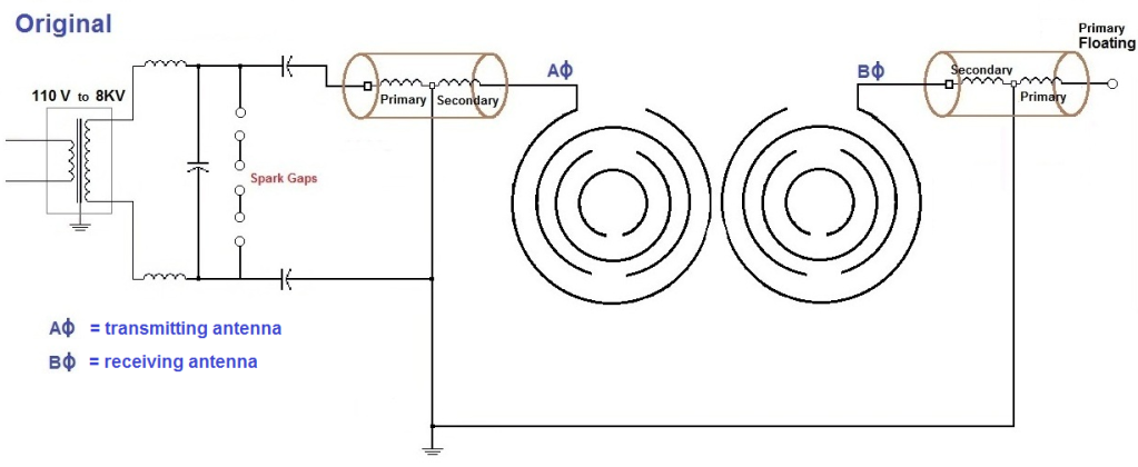
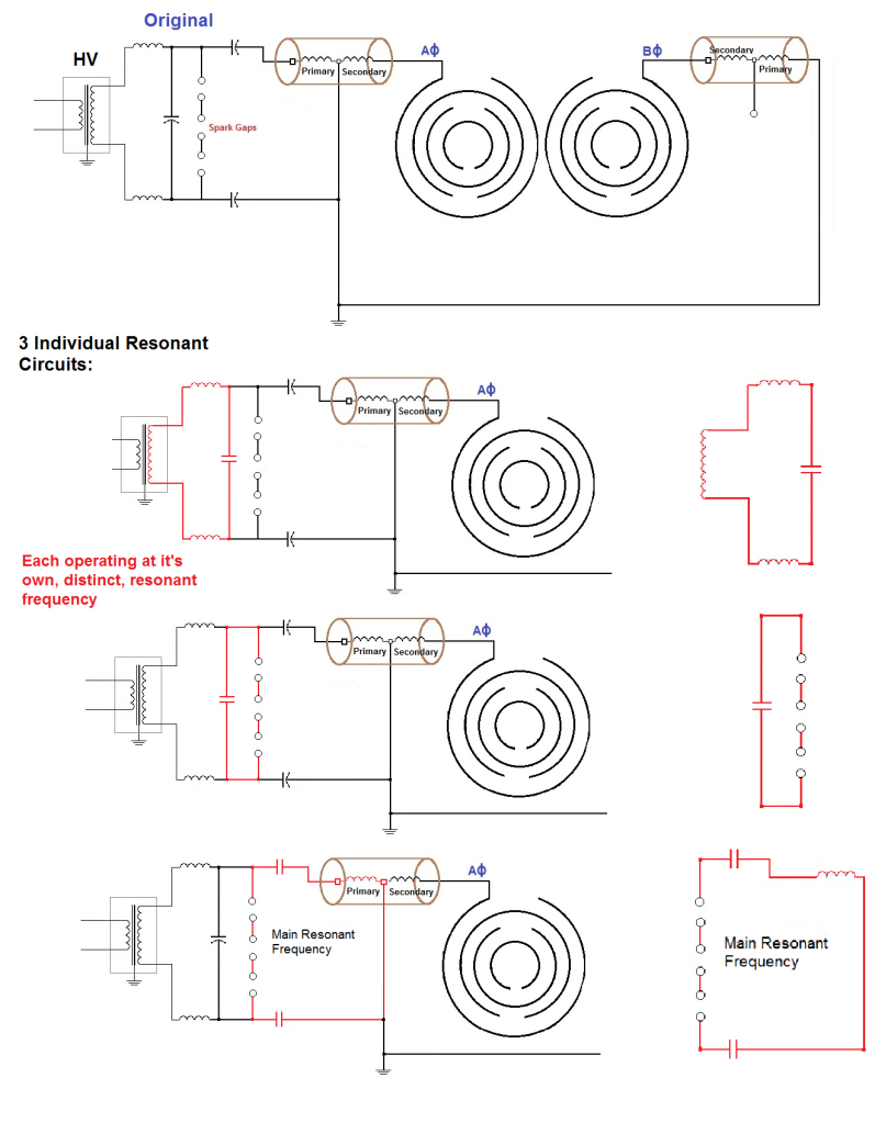
          There seems to be different versions of the original Lakhovsky MWO. Though all operating on the same principle, they have slightly different implementations. The pdf noted above documented three different original Lakhovsky Multi-Wave Oscillators. The differences in the equipment are in the antenna construction, and slight difference in the circuit schematics: Below is the basic original schematic:


          The H.V. transformer provides 8 kilovolts to the circuit. Connected to opposite sides of the HV supply, the two antennas are electrically 180 degrees out of phase with each other. This is important. Inside the brown cylinders are transformers to step up the voltage even higher, but operate not as a regular transformer, but more like a Tesla Transformer, a transmission line. With a high voltage potential between the transmitting and receiving antenna, and the antennas being 180 degrees out of phase, a displacement current flows in between the two antenna. This circuit is asymmetrical, that is, it is not balanced. When Eric first examined the schematic, he didn’t believe it was original, he guessed it was what “somebody else” thought Lakhovsky was doing. After careful examination of the pictures of the original equipment, Eric came to conclude this is indeed the schematic of Lakhovsky’s equipment. Eric referred to this circuit as “driving with the brakes on, but only on one side of the car.”

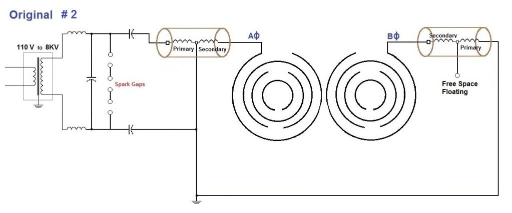
          There is also a second schematic, used in one of the original units which is connected slightly differently:

          Circuit operation
          The receiving antenna is tied to ground, with only the transmitting side being energized(hot). This creates a lopsided situation. Furthermore there really is no “ground” with this system. With the receiving coil connected directly to ground, it lights up the whole neutral circuit of the neighborhood with each impulse from the spark gap. It is basically creating an antenna out of the local neutral wiring. Lots of RF interference! Not good! Eric provided me with the following metaphor regarding this setup:
          “It would be like connecting a wire to one phase of the breaker box in your house, and then connecting this wire directly to a ground rod that has been pounded into the earth.”
          Eric also gave me the following quote regarding the effects of having the system grounded in this manner:
          “It’s more like an electromagnetic terrorist device than a healing tool.”
          Also interesting to note is the receiving antenna primary winding serves no real purpose, it only has one end connected to ground, otherwise it is just floating in space. Eric guesses it was put there just to comply with requirements for a Tesla coil, to have the same mass of primary and secondary. However in the pdf analysis, the researchers made it clear the coils were not operating in a “Tesla mode”.

          Displacement Current
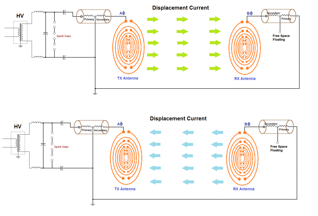
          Before moving on to how the antennas function, let’s take a simplified look at what is happening between the two antennas. They function similar to a capacitor. A high voltage potential exists between the two antennas with an insulator (the air) in the middle, so a displacement current flows. The direction of the displacement current changes, due to the changing polarity placed on the transmitting antenna (the receiving antenna always stays at ground potential). The displacement current flows back and forth, back and forth, as represented pictorially here:


          It must be noted that the displacement current is NOT a continuous wave. We are dealing with impulse currents here. The displacement current flows each time the spark gap is triggered.

          Triggering Circuit
          The triggering circuit is key to providing the proper resonant frequencies. However there are a few problems in Lakhovsky’s original circuit, preventing harmonic oscillations. Looking at the schematic, we have 3 individual resonant circuits on the primary side, each operating at a different frequency:


          The individual circuits are outlined in red. They all collectively contribute to the operating frequency of the spark gap triggering the primary. Thus the operating frequency isn’t a clean, harmonic signal. Each circuit contributes to “noise” in the desired frequency. Herein lies a problem: without a stable driving frequency, how can specific harmonic wavelengths be induced in the antenna rings?


          Oscillations in Ring Antennas
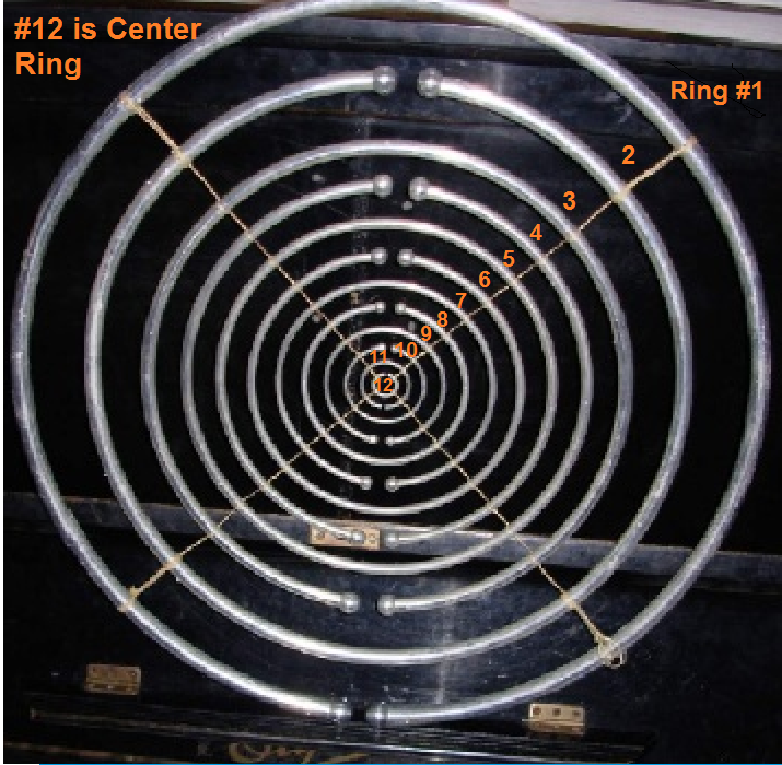
          Lakhovsky’s vision was more than just creating oscillating displacement currents to flow through the body. His antenna design was intended to create the multiple frequencies (TEM) that are thought to be beneficial to the cells. To create the different frequencies, each ring was supposed to resonate at its own unique wavelength, thus the different sized rings. The outer most ring was triggered, and then current flowing in the outer ring would couple through mutual induction with the inner rings. The problem is, in the way the original is setup, very little current can flow into the antenna. Eric estimates only about 1% of the power in the primary circuit can flow into the outer ring and couple with the inner rings. Here is why:
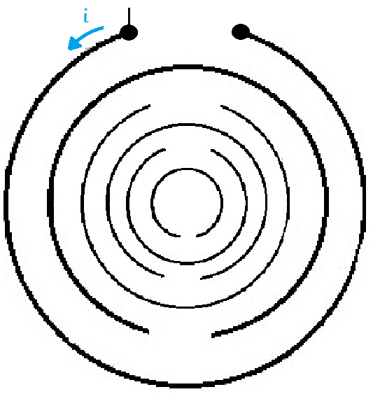
          The outer ring is only connected on one side, which is not a complete circuit path in and of itself. Therefore the outer ring will function only as an antenna, or transmission line. The length of the outer-most ring has both self capacity and self induction, so a small current can flow around it:


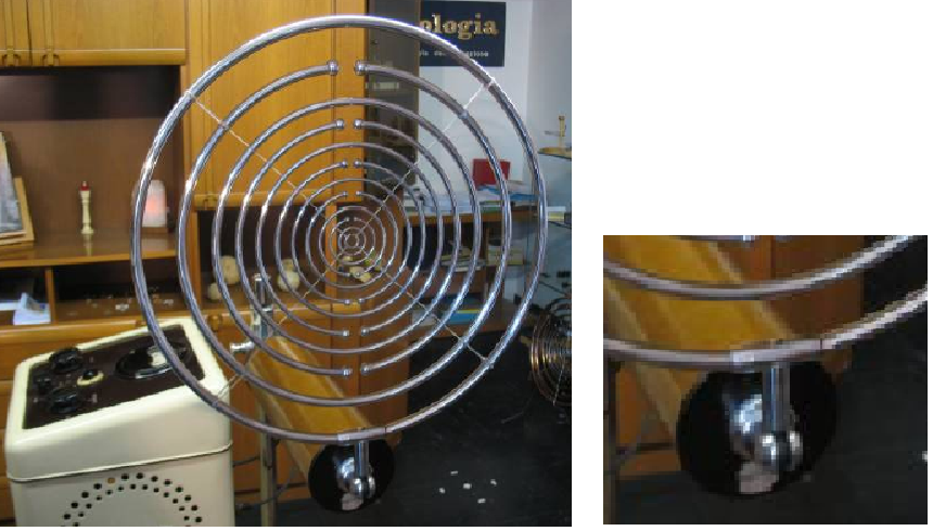
          However the current will become less and less as it couples with the inner rings, which doesn’t lend itself to producing strong signals of varying frequencies. This is why Eric originally didn’t believe this is how the original was configured. He reasoned if current was to be induced into the center rings, the outer antenna could not be only one wire connected. There must be a magnemotive force around the outer ring in order to induce and EMF into the inner rings.. Looking at some of the original pictures, we can see the antennas were in fact one wire connected. It is also evident in the original schematic. First let’s examine the typical MWO setup:


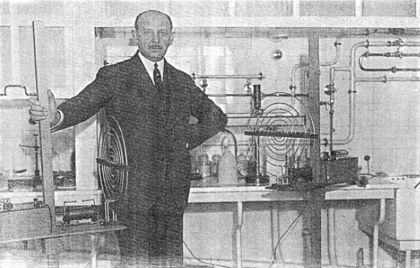
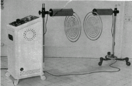
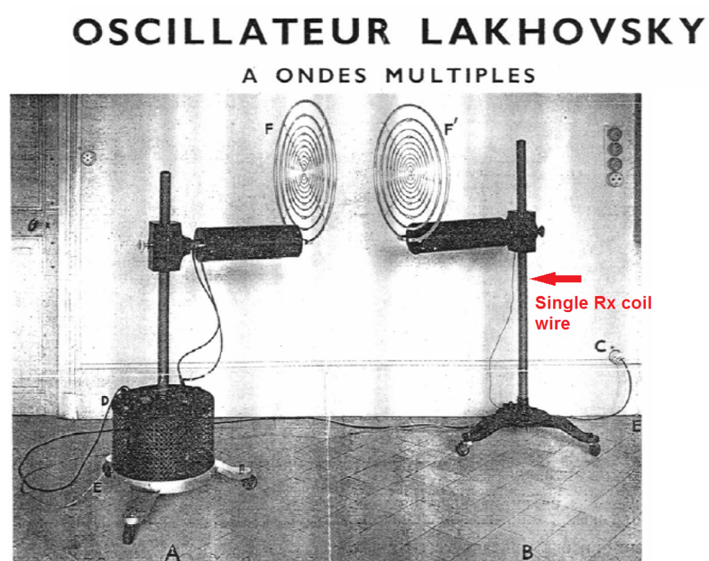
          We have the power supply, and the transmitting and receiving antenna. Note the brown cylinders the antennas are attached to, these contain the “Tesla Coils”. Here is a picture of the inside of one of the cylinders:


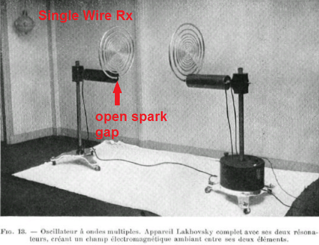
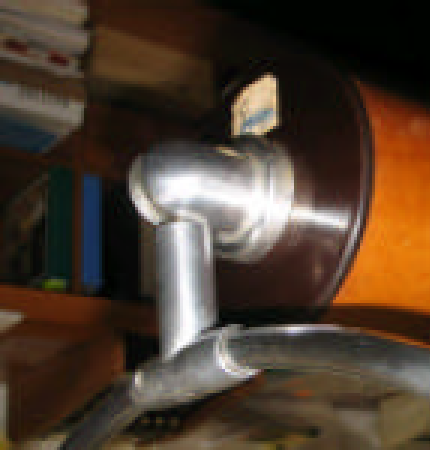
          A couple things to note in this photograph: First the primary is on one side of the secondary, this in itself proves this is not a “balanced” setup. If it were balanced the primary would be in the center of the secondary. Secondly, there is only one wire going from the secondary to the antenna, again showing it is only in one wire operation.

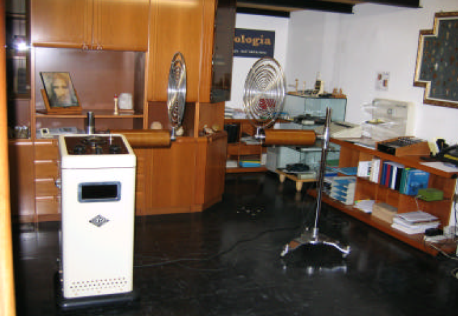
          Another reason Eric at first didn’t believe this to be original equipment is the receiving antenna is only connected to the power supply by one wire (also evident in the schematic). This one wire serves as the ground for the receiving antenna, putting it at ground potential. The problem is, the transmitting antenna will not selectively transmit to the receiving antenna! It will transmit to anything metallic in the room that is at ground potential! Another seemingly flaw in the original design. Here are some more pictures of original equipment, noting only one wire returning from the receiving coil:


          Last edited by jpolakow; 08-14-2012, 03:50 AM.
          Please help support my indiegogo campaign: Cosmic Induction Generator

          Comment


          • #95
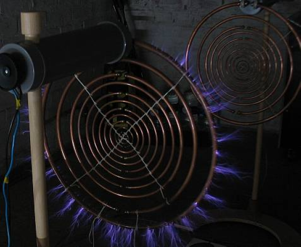
            Now for proof of the effects of having the receiving antenna at ground potential, lets take a look at the transmit antenna under high power. In the following picture the transmit antenna is receiving more power than it normally would, it would not normally produce corona at its edges. Take a look:


            The purple-ish corona at the edges of the outer ring is high voltage on the antenna ionizing part of the air. What is ionizing the air is the displacement current, travelling to ground. The glow can be considered a partial arc, it ionizes some of the air on its way to ground, but not the whole path. What is interesting to note is the direction of the corona. The direction of the corona is the path of the dielectric flux. See how most of it is travelling straight down, to ground? It appears very little of the dielectric flux is travelling to the receiving antenna. The way this is wired, the dielectric flux will take the shortest path to ground.


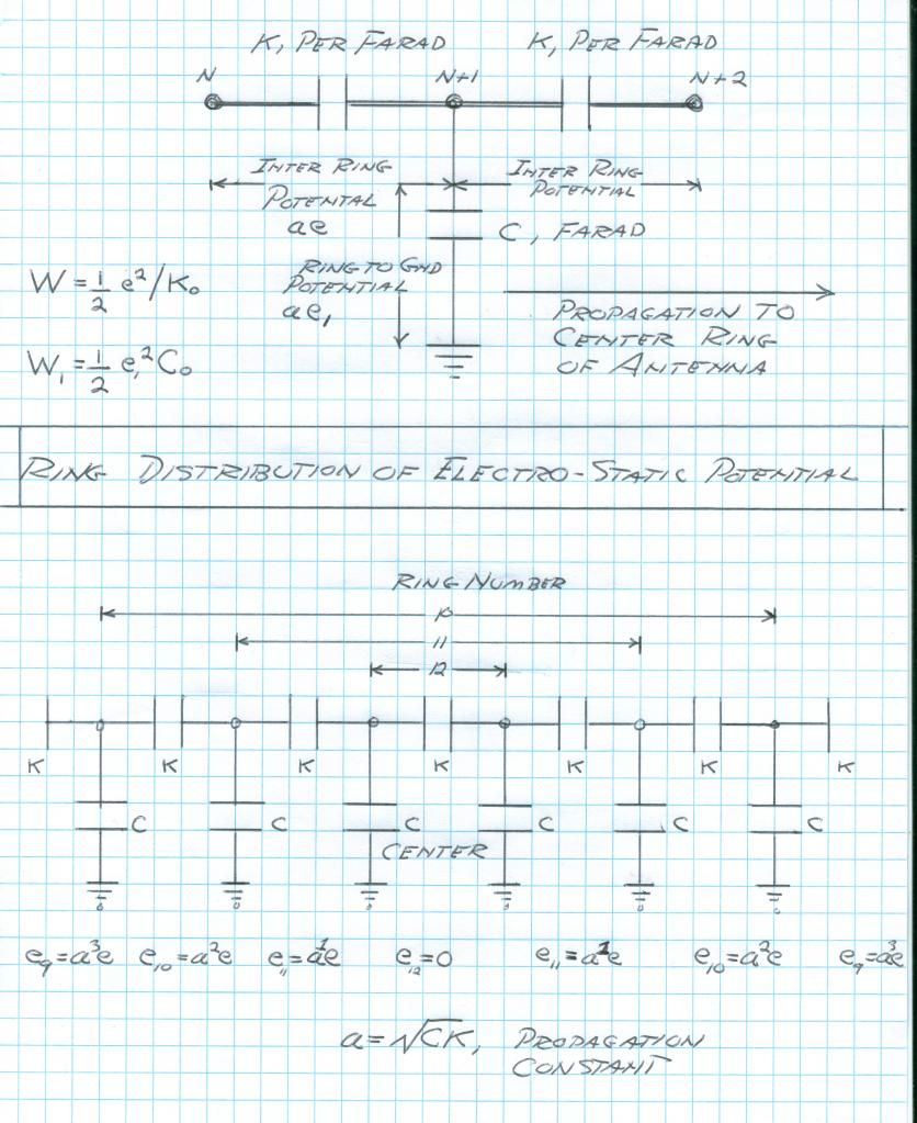
            In the following diagram by Eric, he numbers the rings according to this convention:


            So far we have covered some ideas as to why the original MWO might not have produced a true multi-wave spectrum of RF. Now we will take a closer look, to see if the original antennas were producing much RF at all, or if it was purely a displacement current between antennas.

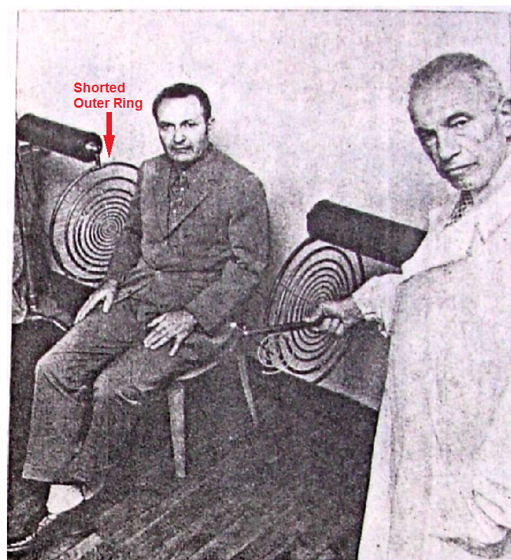
            Looking at some of the pictures of the original antennas, it appears that the outer ring was shorted on both sides, that is there was no spark gap between them. If this was the case, there would be NO magnemotive force; no induced EMF to the center rings, the whole antenna would be at the same potential:


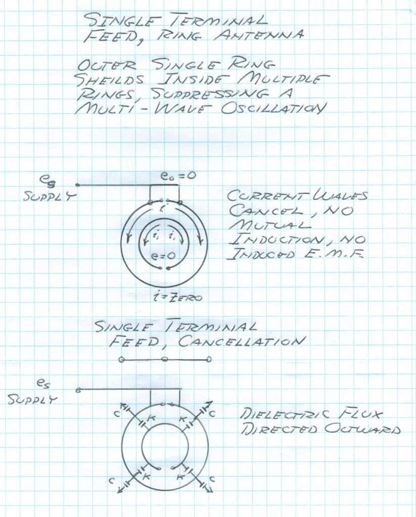
            Not all of the antennas are of this design; there are antennas with an open outer ring as well. For the moment, let’s look at just the ones with a closed outer ring. This would effectively put the entire antenna at one potential, there would be no frequencies emitted! There could be no magnemotive force through the outer ring. Only a displacement current would exist between the two antennas. In this case the antenna construction wouldn’t matter; you might as well just use two plates of metal. The antennas just form a large capacitor! In this case a more apt name might be the “Multi-Wave Capacitor.”


            Here is a diagram by Eric assessing this situation:
            Please help support my indiegogo campaign: Cosmic Induction Generator

            Comment


            • #96
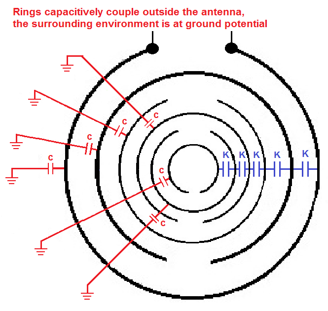
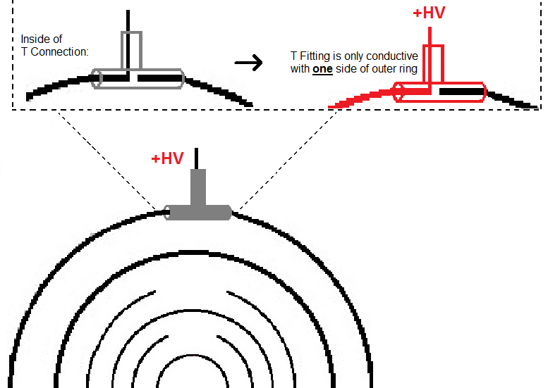
              Looking at the reasearchers analysis of the original MWO, in the pdf noted in the beginning, the researchers noted that one side of the t-fitting was not conductive to the outer ring. That is, the outer ring did not appear to be shorted. There was some type of dielectric in between the outer ring and the t-fitting on one side. They surmised this might have been used to tune the antenna to be resonant to a particular frequency, 43 Mhz. A diagram illustrating the concept:


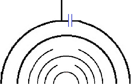
              Still, there would only be a small amount of space in between the t-fitting and the insulated outer ring. What this effectively creates is a capacitor. The circuit would be as follows:


              We all know a capacitor passes AC current, so the outer ring still could be considered “shorted” somewhat, suppressing a current around the outside ring.

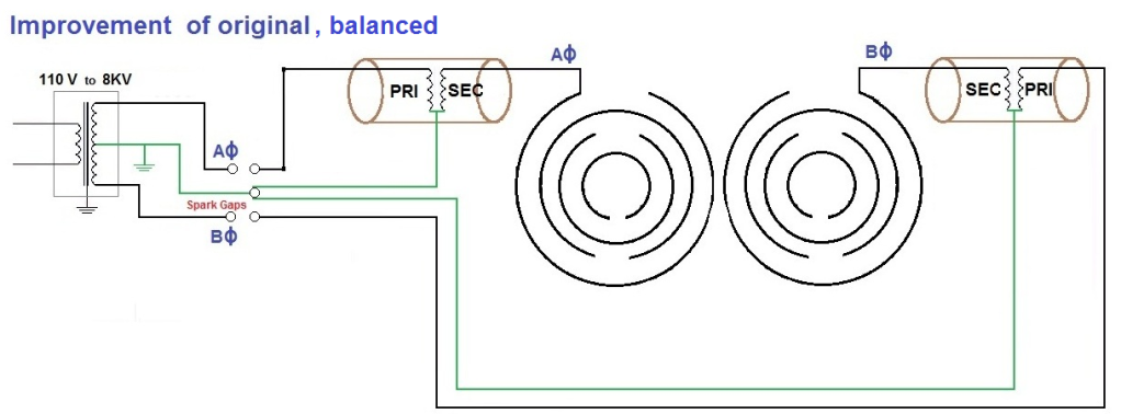
              Having looked at Lakhovsky’s original design, let’s take a look at what Eric originally thought Lakhovsky’s schematic was. He figured Lakhovsky was using a balanced setup, with each antenna being 180 degrees out of phase with relationship to each other, instead of the ground being referenced:


              This design forces all the dielectric flux to flow back and forth between antennas, instead of to the closest ground. Additionally, it would prevent the neutral wiring of your home from becoming a huge antenna.

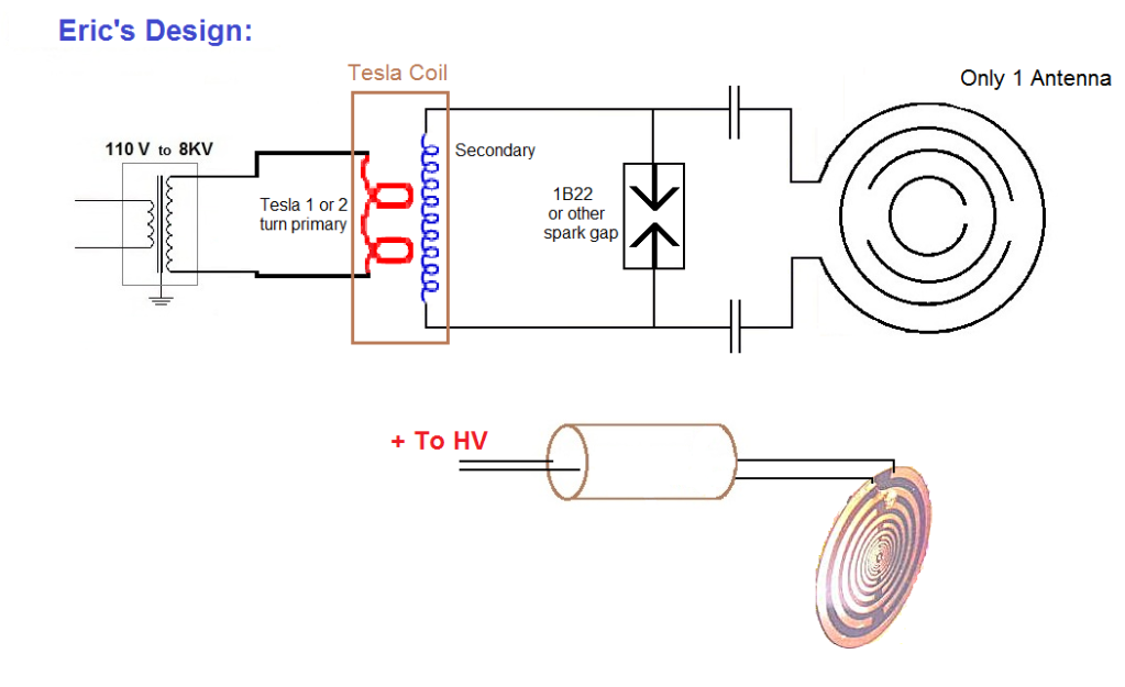
              Now it is time to examine what Eric’s ideal version of what a multi-wave oscillator would be. This is Eric’s design separate from Lakhovsky’s work. To produce a true multi-wave oscillation, you need to produce a magnemotive force (current) in the outermost ring. So naturally the antenna would not be one wire connected, it would be connected on both ends:


              In this design you can get the most magnemotive force(current) flowing in the outer ring, which produces an EMF in the center rings through mutual induction. Each ring oscillates and transmits its own resonant frequency, thus having a true multi-wave, or multi-frequency effect. With this version there is no receive antenna, only one antenna is needed to transmit the multiple wavelength oscillations. This is the way to actually produce a multi-wave oscillation, if that is what Lakhovsky was after. Also the transmit antenna is not limited to producing the individual wavelengths of its component rings. Listed in the additional links section are a few videos, in one of the videos Eric talks about “phantom antennas”. Note in the above picture the flat antenna is markedly different from the tubular ring construction seen in Lakhovsky’s originals, this is an original design by Eric Dollard.

              Antenna Design
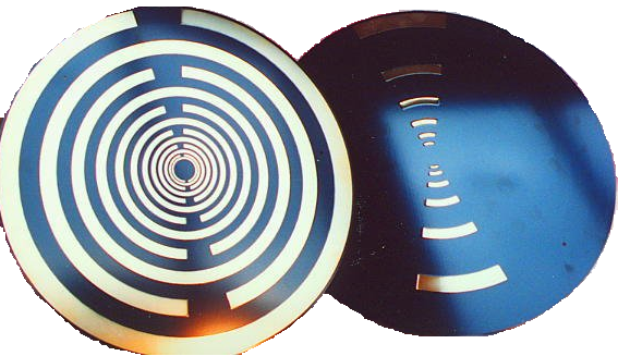
              In Lakhovsky’s antenna, the rings progress in diameter and spacing according to musical scales. Each ring corresponded to a particular note (which scale I’m note sure). Eric came up with a new design. He figured if the goal of the antenna was to preserve and stimulate life, what better progression could there be than that of life itself: the Golden Ratio. This is the “golden ruler” found in nature and the human body. The proportions of the golden ratio are what define this antenna. Eric figured it would be easiest to create this antenna on a circuit board, and just have it plated. Otherwise it is more difficult to get tubes and bend them perfectly, have the correct proportional spacing, suspend them with an appropriate dielectric, and have the correct cross sectional diameter of each tube(this has to be exact according to the geometric progression used as well). Where the Lakhovsky uses spheres at the ends of each ring to form a capacitance, Eric used strips on the back of the printed circuit board:


              Ultimately, Eric’s antenna didn’t require power to have beneficial effects. A sort of interesting piece of evidence: Where he lived there was a cat that would always sleep directly on the antenna. Eric insists a more through investigation of its beneficial effects needs to be studied.

              In summary, Eric says it is difficult to conclude what aspect of the original Lakhovsky Multi-Wave oscillator was producing beneficial healing effects. Was it the weakly generated multiple frequencies? Was it the displacement currents in between the two antennas? Was it the stray RF in the neutral wiring where the MWO was plugged in? It is hard to say. A more thorough study would be required in order to conclude what exactly is the cause of any healing effects. If the healing effects are indeed to multiple wavelength oscillations, he feels his design would perform remarkably better than Lakhovsky’s original.

              Additional Information:
              Excerpt of an article written by Hessel Hoornveld, detailing his meeting with Serge Lakhovsky(George Lakhovsky's son) in 1993:

              I have to agree with Serge that the original Lakhovsky MWO works as no other I know. Furthermore, its antenna is totally different tot that used on other devices. Most use a Bergstresser or Beck antenna, this MWO works with hollow antenna rings, which are tuned. I confirmed that they were really tuned when I checked them using my electronic tuning device. When I tapped the second ring, my tunig device clearly indicated a C Sharp. The outermost ring is a fixed ring directly attached to the coil and is a C. The next ring is a C Sharp, the next a D and so on until the inermost ring, which is a C. In other words, a full octave complete with semitones. If we examine the tuned rings (sound therapy), they also correspond to the chakras (energy points on the body). C is the base chakra, D the sex chakra, E the solar plexus chakra and so on.

              Each antenna ring is made from a different metal. What the metals are was not revealed to me. When I asked why different metals were used, I was told by Serge that they were chosen in connection with the different planetary positions. Although I would not guarantee that I am right, I have taken a studied guess. The outermost ring, the C, is made of brass, the second ring, a C Sharp, of a light rustproof metal, the third of copper, the fourth of brass, the fifth of a light rustproof metal, the sixth of copper, the seventh of brass, the eighth of a light rustproof metal, the ninth of copper, tenth of rass, the eleventh of copper , the twelfth of a light rustproof metal, and the thirteenth of brass. There are bracing wires running from the innermost to the outermost ring, which keep the antenna rings the correct distance apart.

              However, existing photographs of the MWO show antennas with different numbers of rings. I saw one with twelve rings, while Serge's MWO had thirteen with the innermost ring for the bracing wires. I do not know whether the thirteenth ring belongs to the antenna, but it seems very probable.

              SECRECY

              According to Serge, his father's MWO does not work when the moon is full, or when it is enclosed in a Faraday Cage. The rings of the antenna are held together by means of a string, and energy does not flow between them by conduction by but by radiation. The antenna is thus capable of radiating gigantic quantities of energetic energy. The higher and more powerful the energetic field, the faster illnesses and degenerative processes are positively affected. The outermost ring, the C ring, is directly connected to the coil on both sides.

              The reply to my request for a peek into the sanctum of the MWO was a definite no. Nevertheless, I hope that Serge will eventually give his permission because the technology involved is naturally of great interest to us all, and because I feel that his father's work should be open to the view of everyone who is open to it. It seems to me that Serge's fear that his father's techniques would be misused can be ruled out, for there are few people around today who are capable of dealing with this type of energy.

              When Serge demonstrated the MWO, two spark gaps could be seen. There is a large coil behind each of the two antennas, which are brought into resonance with each other. The whole technique is based on oscillation and resonance!! The sound of the two spark gaps is very stable and serene. No sparks jump from one antenna ring to another, as occurs with the Bergstresser and Beck antennas. It's quite safe to come vcery close to the antenna rings with a car key, although sparks begin to jump continuously from a distance of about six centimeters. This does not cause an unpleasant sensation though. This indicates an extremely high voltage, high frequency and extremely rapid pulse behavior through the spark gap, and I suspect that the MWO contains a rotating mechanical spark gap.

              The electricity needed to operate the MWO is supplied from a wall socket, which causes a fair degree of interference in the public electricity supply. This is something which was permitted in the past, but which is actually no longer allowed. Due to such interference, alarm systems, computers, answering machines and telephone systems etc. could suffer damage, or start to lead a life of their own. It was only possible to operate the MWO for a short period of time, about five minutes, or else it would overheat.

              The device is grounded through the mains. It may be that this was done in order to enable the feed cable connected to the wall socket to be used as a (capacitor). This works even when an earth connection is not present.

              Serge did not want to answer my question concerning the relationship between his father, George Lakhovsky, and Nikola Tesla; a brief silence followed. We know from available information that the two worked together, and that Tesla was also involved in the development of the MWO. Nikola Tesla had more than 1.000 patents to his name, and was the discoverer of alternating current, and induction motors.


              Links:
              Tom Brown Site: What is a Multiple Wave Oscillator

              U.S. Psychotronics Association MultiWave Oscillator (part 1 of 5):
              U.S. Psychotronics Associations - Multi Wave Oscillator presentation (Part 1 of 5) - YouTube

              Lakhovsky MultiWave Oscillator(part 1 of 4):
              Lakhovsky Multiple Wave Oscillator 1/4 - YouTube

              Also take a look at Dave's (Web00x) posts. He has been busy building a MWO
              Please help support my indiegogo campaign: Cosmic Induction Generator

              Comment


              • #97
                Secondary and extra coil testing

                dR-Green:
                I did some more testing with the coils. The can was on top of the extra coil (axial direction). Bottom of extra coil connected to top of secondary and ring. Top condenser ring connected to ground as was the meter grounded. I varied the condenser rings spacing as noted below. I measured two distinct frequencies for each test.

                Ring spacing 1st resonance 2nd resonance

                60 mm 984.6 Kc 1,688.2 Kc
                30 mm 922.4 Kc 1,635.2 Kc
                18 mm 873.0 Kc 1,603.0 Kc
                2 mm 735.0 Kc 1,554.3 Kc

                Next I will go back to the new secondary with .087" (almost #11 AWG) and run some test with different wire spacing. Following those tests I will suspend any further testing until I am back home in the US. We are moving back at the end of October, but all household items (including the hobby ones) must be packed for transportation by the middle of September. I will yet publish the secondary wire spacing results and then just read the forum entries. I hope by end of November I will be in position to continue the CRI. Also I may be close enough to Eric to pay him a personal visit. In the mean time I am considering to travel to Belgrade by train and pay homage to Tesla by visiting the Tesla museum.

                Comment


                • #98
                  The End

                  The coyote got into the rat poison and is puking violently, soon it will be dead.

                  I have just been informed that Olin Bales has destroyed the Landers Station. The ransom was not paid. My purpose for engaging in this E.G. Forum was an attempt to prevent this disaster, but now this purpose is obviated. Bales made good money scrapping my station and its tools and cars, now he is on to his next victim, with full protection by "The Law". Therewith closes my research, replacement is impossible, the materials are no longer available.

                  No more trips are to be made to "Prison Planet dot T.V.", it is over. If you sleep in a "Revenue Shack" the dog outside your window barks all night, by day it is barking savages whacking at their balls. If you try to sleep outside in your car on some back road, you are interrogated by the Cops. Yes indeed, freedom in "Prison Planet dot T.V." it's great to be free, isn't it?

                  Recently I was asked to be on an Interview by a so called "Free Energy" program. Free again, its all Free. No interest in my electrical work here, just Chemtrails, H.A.A.R.P. and related Soviet Scalar Conspiracies. Then I was called a piece of **** for not being a "Believer". To compound the event it was explained that my response was the result of a "Bad Attitude" and I won't get anywhere like that. Where would I get anyway.

                  Here on this E.G. Forum rested the hope that things could be renewed and or salvaged. This is not the case. At its best the individuals that make this group are indentured into servitude to the Harlot. Little choice exists in this matter, but one is led to believe your life is a result of your choices. In reality to even call it a "Life" is a delusion, and then demand it upon others who want no part. Even the most able, willing, and dedicated are hopelessly mired in the honey that drips from the Harlot. On the other end in the E.G. Forum, the worst, is the sodomizer of sheep, his credo, "I don't know anything, so you don't either." Taking the average between maximum and minimum values is a quantity of little value.

                  Two productive efforts grew out of this interval on the E.G. Forum, The Tesla Trancieving Transformer, and the Parametric E.M.F. This is well under way and there is little for me to add. At this point it seems that the beloved E equals mc Square went down the bowl. No energy equivalence exists in a Parametric Source of E.M.F. But this is yet to be proven.

                  Because of the circumstances outlined above along with others not mentioned I will no longer have any interaction on the E.G. Forum. This is no longer possible. Here the daily routine is to sit in the car in the shade, or hike around for miles in the desert heat. Little else is possible in America, other than to serve her. Thus out of boredom I will in all probability continue to write on those things which I study in the front seat of my car, they most likely will continue to appear here but I am rather inclined to throw them in the trash when finished.

                  QRT DE N6KPH SK...
                  SUPPORT ERIC DOLLARD'S WORK AT EPD LABORATORIES, INC.

                  Purchase Eric Dollard's Books & Videos: Eric Dollard Books & Videos
                  Donate by Paypal: Donate to EPD Laboratories

                  Comment


                  • #99
                    Originally posted by T-rex View Post
                    Taking the average between maximum and minimum values is a quantity of little value.
                    If that is a reference to my recent tests then it should be pointed out that there are no min max or average readings here. The presented data is simply a visual representation of the respective tuning of the secondary and extra coil that allows for resonance at F - what they are doing when tested alone under those conditions. The values are converted into ratios/percentage with the idea being that it will be easier to see if the ratios are constant on every scale of coil. This is mainly for future convenience of set up and tuning, assuming the ratios are constant.

                    For example, on my existing coil, if F = 3670 kc, by tuning the secondary to 60% of F and the extra coil to 87.5%, then I know I will have resonance at 3670 kc, and the Tandem mode frequency will be approx 50.5%. Any combination of tuning can now easily be set up and tested.
                    Last edited by dR-Green; 08-14-2012, 02:01 AM.
                    http://www.teslascientific.com/

                    "Knowledge is cosmic. It does not evolve or unfold in man. Man unfolds to an awareness of it. He gradually discovers it." - Walter Russell

                    "Once men died for Truth, but now Truth dies at the hands of men." - Manly P. Hall

                    Comment


                    • Originally posted by dR-Green View Post
                      If that is a reference to my recent tests then it should be pointed out that there are no min max or average readings here. The presented data is simply a visual representation of the respective tuning of the secondary and extra coil that allows for resonance at F - what they are doing when tested alone under those conditions. The values are converted into ratios/percentage with the idea being that it will be easier to see if the ratios are constant on every scale of coil. This is mainly for future convenience of set up and tuning, assuming the ratios are constant.
                      I honestly haven't paid attention to your more recent posts due to being busy winding coils and not wanting to overload my mental plate, so my apologies if I am wrong with this thinking. This most recent T-Rex transmission was labeled the 5th of August by the U.S. Postal Service, the same day that I told Eric about his Landers station being disassembled so if your post was more recent than that date, not to worry, not directed at you. I feel that Eric's description of the average value between min and max being of little value was directed at people that say that Eric's (many) observations are wrong and his ideas can't work (minimum observations, Kokomoj0). That was my first impression of the statement... Besides, everytime I talk to him, he seems to indirectly commend your efforts on the TMT.

                      Dave

                      Comment


                      • Originally posted by Web000x View Post
                        I honestly haven't paid attention to your more recent posts due to being busy winding coils and not wanting to overload my mental plate, so my apologies if I am wrong with this thinking. This most recent T-Rex transmission was labeled the 5th of August by the U.S. Postal Service, the same day that I told Eric about his Landers station being disassembled so if your post was more recent than that date, not to worry, not directed at you. I feel that Eric's description of the average value between min and max being of little value was directed at people that say that Eric's (many) observations are wrong and his ideas can't work (minimum observations, Kokomoj0). That was my first impression of the statement... Besides, everytime I talk to him, he seems to indirectly commend your efforts on the TMT.

                        Dave
                        I see, thanks for the clarification Dave
                        http://www.teslascientific.com/

                        "Knowledge is cosmic. It does not evolve or unfold in man. Man unfolds to an awareness of it. He gradually discovers it." - Walter Russell

                        "Once men died for Truth, but now Truth dies at the hands of men." - Manly P. Hall

                        Comment


                        • Originally posted by Nhopa View Post
                          Next I will go back to the new secondary with .087" (almost #11 AWG) and run some test with different wire spacing. Following those tests I will suspend any further testing until I am back home in the US. We are moving back at the end of October, but all household items (including the hobby ones) must be packed for transportation by the middle of September. I will yet publish the secondary wire spacing results and then just read the forum entries. I hope by end of November I will be in position to continue the CRI. Also I may be close enough to Eric to pay him a personal visit. In the mean time I am considering to travel to Belgrade by train and pay homage to Tesla by visiting the Tesla museum.
                          Sounds like a good plan, it would be nice to see the stuff up close too I'm going to get some of the materials to make a bigger coil tomorrow, but I'm not quite sure what to build yet I'm going to test two different lengths of wire on the extra coil, possibly rewind the secondary with thicker wire to see if the magnification factor peak shifts at all, and then that should be the end of the testing on this coil. Next will be a CRI frequency coil at 882 kc. The frame of that will be made from MDF rings with white PVC round conduit as the rods.
                          http://www.teslascientific.com/

                          "Knowledge is cosmic. It does not evolve or unfold in man. Man unfolds to an awareness of it. He gradually discovers it." - Walter Russell

                          "Once men died for Truth, but now Truth dies at the hands of men." - Manly P. Hall

                          Comment


                          • Originally posted by Nhopa View Post
                            I did some more testing with the coils.
                            Could you test the secondary alone again and see where the magnification factor is highest? I'm thinking that if it's universally around 60% of F then depending on what happens in the next extra coil tests, the secondary could be looked at so it can be tuned to 60% for highest magnification factor, with the size of the coil adjusted to make this fall on the right frequency for the system
                            http://www.teslascientific.com/

                            "Knowledge is cosmic. It does not evolve or unfold in man. Man unfolds to an awareness of it. He gradually discovers it." - Walter Russell

                            "Once men died for Truth, but now Truth dies at the hands of men." - Manly P. Hall

                            Comment


                            • 8.0" Diameter Extra Coil Summary


                              * C is the coupling test capacitance between oscillator and coil.
                              ** Fo is the center frequency measured with a storage oscilloscope.
                              Last edited by Geometric_Algebra; 08-15-2012, 01:55 AM.

                              Comment


                              • Lakhovsky's MWO

                                Interesting posting by jpolakow. The original patent by George Lakhovsky shows a capacitive discharge MWO. It appears this present posting suggests a inductive discharge MWO. Interesting to note that Dr. Bob Beck's MWO also employed a inductive discharge for which he was criticized in the book "The Lakhovsky Multiple Wave Oscillator Handbook" published by Borderland Sciences. Reading this current posting one gets the feeling that Lakhovsky was all "screwed" up with his design, yet it seems his MWO worked quite well as can be seen in his book "The Secret of Life" and as claimed by Dr. Bob Beck, who rediscovered and publicized the Lakhovsky MWO in the 1960's.

                                Comment

                                Working...
                                X