Announcement

Collapse
No announcement yet.

Eric Dollard

Collapse
This is a sticky topic.
X
X
 
  • Filter
  • Time
  • Show
Clear All
new posts

  • Originally posted by Web000x View Post
    Hey everybody,

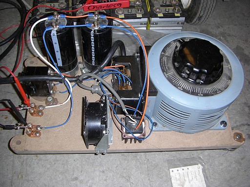
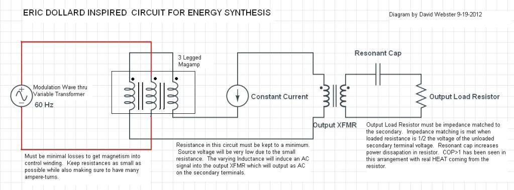
    I know that a lot of us found our quest into the alternative science literature in search for an alternative energy source. It has been a long quest of sacrifice, but thanks to Eric Dollard, it has begun to pay off for me. I don't have a lot of time to explain all of the little details because those will have to be tackled according to the material that you choose to use, but here is the basic bare bones circuit that I am using and am definitely 'Synthesizing Energy'.


    Dave

    [/B]
    Hi Dave.

    You are merely resonantly phase shifting conduction angle.

    Make your source a battery driven pure sine power inverter and see how much power you are really using !

    Cheers ........... Graham
    Comment


    • Originally posted by GSM View Post
      Hi Dave.

      You are merely resonantly phase shifting conduction angle.

      Make your source a battery driven pure sine power inverter and see how much power you are really using !

      Cheers ........... Graham
      Hey Graham,

      I know that over time we become ever more skeptical of such claims of 'free energy' and try to find out where the researcher has gone wrong in his measurements, but I assure you this circuit is the real deal.

      I don't have a pure sine wave inverter, but I do have one that puts out a 'spikey' 60Hz wave. I hooked it up to the variac that is feeding the constant current source and there was no difference in DC power being delivered from the battery while the circuit was being modulated vs. the modulation circuit being unpowered. The heat being developed in the output resistors is definitely a function of the parameter variation.

      Just build it and see.

      Dave

      Comment


      • For those of you who don't have magamps and don't want to wind toroids, go browse this site: Homemade Magnetic Amplifiers.. I'd be willing to bet that you can achieve the same effect as me using conventional transformers hooked up like the 'Magnetic Amplifier with Reactance Coils in Series' configuration shown on that page.

        Dave

        Comment


        • Originally posted by Web000x View Post
          My constant current consists of 120V 60 Hz wall socket EMF that is fed into a variable transformer that feeds a full wave bridge rectifier that charges my Constant Current Source which is a capacitor. It is important that there NOT BE ANY UNNECESSARY RESISTANCE in the constant current circuit; this is the reason for using a source capacitor instead of a low voltage, low amp hour battery which has inherent resistance. **This is all for theoretical analysis and not practical use as of yet**
          Kind of like this (being used to charge some batteries for a shopping go-cart), with large electrolytic caps in parallel to the bridge rectifier?


          Originally posted by Web000x View Post
          I just tried replacing my two smaller transformers with two microwave oven transformers that have LOWER RESISTANCE and HIGHER FLUX DENSITY CAPACITY and was able to get up to a 2600% net output and a 600% total output.
          You do not mean you are replacing the mag-amp toroids with 2 MOTs, correct? But replacing an input transformer to the toroid with a MOT to saturate the mag amp toroid's core with a higher voltage and the other MOT replacing the output transformer?

          Originally posted by Web000x View Post
          Net Output = (Total Output Watts)/(Input Loss Watts - Modulation Step-Up Transformer Watts) = 2600%

          Total Output = (Total Output Watts)/(Total Input Watts) = 600%

          The reason for the modulation step-up transformer is because it inductance of the control winding is so large that applying a direct 120V 60 Hz doesn't pass enough current to saturate the core. I have a variac connected to a microwave oven transformer (MOT) that modulates the control winding with the higher voltage. The MOT secondary winding has about 120 Ohms of resistance compared to the 14 Ohms in the control winding. Naturally, since the resistance of the secondary winding of the MOT doesn't play a role in the system under study, I left it out of the 'Net Output' calculations.

          Dave
          Dave, if I understand what you said clearly - I don't think you can't use i^2*R for the coils to get input power due to the phase angle. Using that actually will give you higher input power calculations than acutal, so the reported efficiencies you report would be actually LOWER than the actual efficiencies (if my reading of your post was correct). You would be under-reporting how good the system really is. If my memory serves me correctly, using (SQRT(2)/2)*V*I*cosine(angle) is better and will give you the RMS power value.


          You probably got that all figured out but I wanted to be clear in case someone else also read that as I did.

          If I may offer a suggestion, since your input power supply to the Toroids is a Variac and your Constant Current supply is also a Variac... I suggest just plugging each variac through a couple of kill-a-watt meters to get total power for each of those to cut off any naysayers to what the real input power is - since that would include all core losses and any other power being used at that point of power input. It would also eliminate arguments that it's some phase angle issue.


          You could also use a bridge rectifier and large cap at the output to produce a DC voltage over your known resistance to eliminate any power calculation errors there that some may claim.
          Last edited by SilverToGold; 09-20-2012, 05:29 PM.

          Comment


          • Thanks again Eric

            Dave,

            Very nice !! this is quite encouraging and exciting. Just wanted to say thank you for all your effort and contributions on the forum here.

            I do realize that much of what Eric has worked on, the hand made equipment, and his countess hours of research that is lost is priceless and maybe no amount of money can replace this.

            However Eric, There are wonderful, giving, caring people all over this world and there is a huge following of people that care about you and your work. Yes there have been
            a huge amount of hits on this forum in your name.
            (keep in mind though that for your average guy trying to understand your work, if like me.. is responsible for hundreds maybe thousands of those hits)

            I am not trying to downplay the traffic here on energeticforum ....
            I love this place

            The truth is though if you want to raise some capital for living, a lab, or whatever .....This group on here does care and wants nothing more than to see you come out on top .... and not gone to the bushes for good.

            This is a very limited group of people here though and limited funds.
            To really make a significant financial move it is going to take more wheels than this limited group here to pull it off.

            Maybe we cant raise a half a million for a new fancy lab...but even if we raised enough for you to buy a parcel of land with a shack in the woods somewhere so you can sleep under the stars with the coyotes and say screw the rest of the world on your own terms .... wouldn't that be
            worth a shot.

            I think there is enough study of the human filth already... seriously when is the last time you watched TV ??.... it is nearly all a study of human scum.


            All in All ... its really none of my business and maybe that's what you will tell me.


            Eric, If you ever want to get away for a couple weeks
            your are more than welcome to come crash with us. We have a small place across from the beach on Florida's gulf coast. Its not luxurious or anything you could crash on the couch its small but its home. I have no agenda other than to get to meet you and put back a couple of beers with you.
            I dont know if you fly but we would fly you out and back!

            This offer will always stand so if it gets to chilly in the winter come warm up in Florida for a couple weeks if you want.

            Take care

            Nate & Laura

            Comment


            • Originally posted by SilverToGold View Post
              Kind of like this (being used to charge some batteries for a shopping go-cart), with large electrolytic caps in parallel to the bridge rectifier?


              Yes, that is how I am charging my capacitor.

              You do not mean you are replacing the mag-amp toroids with 2 MOTs, correct? But replacing an input transformer to the toroid with a MOT to saturate the mag amp toroid's core with a higher voltage and the other MOT replacing the output transformer?

              In my original diagram, I only showed one output transformer for the sake of simplicity. In reality, I have put two transformer primary windings in series to have two output transformers to siphon off more energy. I replaced the original output transformers (Radioshack 50VA 5:1 Transformers) that I was using with two microwave oven transformers (MOT). Two microwave oven transformers now constitute the output transformers.

              There is another MOT in the circuit that is not shown for the sake of diagrammatic simplicity. It is delivering EMF to my control winding because of the incredibly large inductance of the control winding. This way I can deliver enough current to the winding.

              The circuit has three MOT's, One powering the control winding, and two acting as output transformers.


              Dave, if I understand what you said clearly - I don't think you can't use i^2*R for the coils to get input power due to the phase angle. Using that actually will give you higher input power calculations than acutal, so the reported efficiencies you report would be actually LOWER than the actual efficiencies (if my reading of your post was correct). You would be under-reporting how good the system really is. If my memory serves me correctly, using (SQRT(2)/2)*V*I*cosine(angle) is better and will give you the RMS power value.

              Yeah, I understand this, but the way that I am measuring this, I am looking for REAL losses that come from the resistances in the wire. i^2R is the real power losses within the modulation winding. Because I am not trying to multiply the EMF at the terminals of the control winding by the current going into the winding (which would have a phase angle associated) , I don't need to worry about phase angle. No matter what the phase angle of ANY circuit, i^2R represents the resistive losses regardless.


              You probably got that all figured out but I wanted to be clear in case someone else also read that as I did.

              If I may offer a suggestion, since your input power supply to the Toroids is a Variac and your Constant Current supply is also a Variac... I suggest just plugging each variac through a couple of kill-a-watt meters to get total power for each of those to cut off any naysayers to what the real input power is - since that would include all core losses and any other power being used at that point of power input. It would also eliminate arguments that it's some phase angle issue.

              Yeah, I have thought about that, but wanted to get other people up to speed with replication information first. I don't need to convince anybody else so long as I can build something that works.


              You could also use a bridge rectifier and large cap at the output to produce a DC voltage over your known resistance to eliminate any power calculation errors there that some may claim.

              Yeah, I have analyzed the hell out of this using DMM, Analog MM, and two different scopes, one with math functions to be able to project a Power wave on the screen. I am convinced that this is real. The heat from the resistors burns me and makes my lab smell like electrical fire. There is very little doubt in my mind of what I am seeing.
              Response in blue above.

              Dave
              Last edited by Web000x; 09-20-2012, 08:06 PM.

              Comment


              • Thank you for your reply, makes things clearer.

                Sounds VERY good and thank you for getting us all up to speed!

                This is pretty exciting and I firmly believe Eric is correct about Parametric Variation being a provable (mathematically and experimentally) means for energy "synthesis" - so I believe your basis is firm and your results correct.

                God Bless

                Comment


                • Various

                  David,
                  Well done!
                  Thankyou for the clear and precise information transfer.

                  Planned some years back to do the Marks TPU but had too many questions and so have two open grained Toroids here of 3" and 4.75".
                  What size Toroid are you using please?
                  Is there anything that you feel you would like or need to change to improve performance that you may have considered?
                  One comes to mind where the Toroids are wound on top vice alongside where energy transfer may be greater - a greater surface area of contact so to speak.
                  Asking these questions as I will probably replicate.

                  Chris Carson in Video 4&5 of the SBARC Lecture series, shows us a Toroid where it is said to act like a sponge in receiving the induced magnetic energy from the Primary Coil but then on the Secondary side how do we really get that same energy induced into the Copper if the Toroid Iron 'is acting like a sponge'?
                  Does anybody have an answer for this, David, Eric?

                  Have been looking for Chris Carson's Video on his electrostatic rotating capacitor device but cannot find it.
                  Can anybody help please as it appears to be no longer available?

                  Thankyou for pointing me to the Silver Mica Capacitors for high voltage as I had neglected the Audio Amp side.

                  Building Aluminium chassis here for the Regen Magnifying Receiver and looking at an adjustable power supply that covers about 200v to 1200v and found one in the 1964 ARRL Handbook on page 237 - uses voltage regulators for each adjusting group.
                  Next is a Bias supply and the pages after the above also have some good schematics.
                  Will upload later into Files at 'n6kph' for those interested.

                  The 3 major problems with Vacuum Tube technology is a suitable chassis, suitable power supply and suitable bias supply.
                  I have never considered Vacuum Tubes as ever being a problem like the 3 above.
                  Thanks.

                  Smokey

                  Comment


                  • Originally posted by David G Dawson View Post
                    My apologies to all if I have come over strong and you have all failed to understand what I have been talking about with the Math but it stands as presented without correction.
                    Hi David. I'm glad you're still around, I was looking over some of your posts the other day and wanted to ask you if you could repost it in a different format, similar to what I and others have posted. I don't know what you mean when you say "all metal" picks up a signal or something, also things like "Level 1". Could you possibly provide graphs or post the resonant frequencies of the coils with the wire lengths and frame dimensions, because I don't have a clue what's what.

                    Also have you done any Tandem and Concatenated mode tests? I would like to have a better idea of what's going on in your setup particularly with the different extra coils.

                    As for your troubles with posting images, why not use imageshack or photobucket etc, it's much easier.

                    Thanks
                    http://www.teslascientific.com/

                    "Knowledge is cosmic. It does not evolve or unfold in man. Man unfolds to an awareness of it. He gradually discovers it." - Walter Russell

                    "Once men died for Truth, but now Truth dies at the hands of men." - Manly P. Hall

                    Comment


                    • Dave,

                      Don't know why but, I look at your circuit diagram and I see what - Kapandze!

                      Penno

                      Comment


                      • Kapanadze or not Kapanadze the principle is the same.

                        Comment


                        • Csi

                          Hi David. I'm glad you're still around, I was looking over some of your posts the other day and wanted to ask you if you could repost it in a different format, similar to what I and others have posted. I don't know what you mean when you say "all metal" picks up a signal or something, also things like "Level 1". Could you possibly provide graphs or post the resonant frequencies of the coils with the wire lengths and frame dimensions, because I don't have a clue what's what.

                          Also have you done any Tandem and Concatenated mode tests? I would like to have a better idea of what's going on in your setup particularly with the different extra coils.

                          dR-Green,
                          Thankyou for asking and will try and work something out with appropriate drawings and yes I can see how confusing it can be.

                          CSI sits there waiting for the next stage but haven't quite caught up here and am having a problem in identifying how one can determine whether a device is working in a Tandem or Concatenated manner.
                          Appears I have missed something that could clarify that matter.

                          Tried many other coils that were not of the nature as the Extra wrt turns or size or dimensions etc.
                          All of these coils worked to some degree but not as good as my first accidental with the 50 turns of 14 awg.
                          Was hoping that all of these coils would work inside the Secondary but that proved to not be the case, a 1/2 coil yes but not a full.
                          Measured distance through air with re-radiation pickup by the probe head was the criteria used here to determine comparisons.

                          I tried to delete my files but had great difficulty as I was unable to identify any files to delete and don't quite agree with this method as anybody new would be missing the earlier data.
                          We simply don't have enough space here and why I prefer 'n6kph'.

                          'Level 1' is simply a reference to a signal strength from 0 to 10 and Level 1 is very weak where 5 is mid range and 9 is pretty strong.
                          Eric would use QSA 1 to 5, same thing.
                          'all metal' means anything that is metallic in nature and this would be referring to any sort of metal bracing like in my Carport or the metal roof or any metal lying around would have this AM Radio Signal on it and the probe head with contact was able to pick up that signal and rectify it so I could hear it in the high impedance Headphones.

                          Will see what I can come up with.

                          Smokey

                          Comment


                          • Manganin Winding Wire

                            Manganin winding wire:
                            (Copper 86%, Manganese 12%, Nickel 2%)

                            Have managed to pickup two coils of this wire, one in 28 and the other in 38 awg.
                            Screening is a rayon/silk and quite amazed by this technology and how it is done.
                            Would like to ask Eric if he knows of any particular use for this wire other than as a 'high resistance wire' and being insulated must have had a winding purpose other than for use in Rheostats where you would use spaced uninsulated.
                            Resistance is 5x that of Copper.
                            Would this be a winding candidate for David Websters device?
                            Thanks.

                            0A4Gs have arrived for the Receiver, 3 are from Sylvania (vertical round tube shaped cathode) and the other from RCA (the bell shaped cathode).
                            Just Love that Violet glow!
                            Also received 2 x 6AG7s for Oscillator use.

                            Smokey

                            Comment


                            • Originally posted by David G Dawson View Post
                              David,
                              Well done!
                              Thankyou for the clear and precise information transfer.

                              Planned some years back to do the Marks TPU but had too many questions and so have two open grained Toroids here of 3" and 4.75".
                              What size Toroid are you using please?
                              Is there anything that you feel you would like or need to change to improve performance that you may have considered?
                              One comes to mind where the Toroids are wound on top vice alongside where energy transfer may be greater - a greater surface area of contact so to speak.
                              Asking these questions as I will probably replicate.

                              Chris Carson in Video 4&5 of the SBARC Lecture series, shows us a Toroid where it is said to act like a sponge in receiving the induced magnetic energy from the Primary Coil but then on the Secondary side how do we really get that same energy induced into the Copper if the Toroid Iron 'is acting like a sponge'?
                              Does anybody have an answer for this, David, Eric?

                              Have been looking for Chris Carson's Video on his electrostatic rotating capacitor device but cannot find it.
                              Can anybody help please as it appears to be no longer available?

                              Thankyou for pointing me to the Silver Mica Capacitors for high voltage as I had neglected the Audio Amp side.

                              Building Aluminium chassis here for the Regen Magnifying Receiver and looking at an adjustable power supply that covers about 200v to 1200v and found one in the 1964 ARRL Handbook on page 237 - uses voltage regulators for each adjusting group.
                              Next is a Bias supply and the pages after the above also have some good schematics.
                              Will upload later into Files at 'n6kph' for those interested.

                              The 3 major problems with Vacuum Tube technology is a suitable chassis, suitable power supply and suitable bias supply.
                              I have never considered Vacuum Tubes as ever being a problem like the 3 above.
                              Thanks.

                              Smokey
                              Hey Smokey,

                              Those toroid dimensions sound like they will be comparable to mine. Here is the toroid that I used: Toroidal O-Core OA-250

                              One thing that I would do differently for experimental purposes would be to make taps or have multiple inductors that constitute the power winding. The reason for this is because if you want to try to parameter vary any decent amount of Constant Current, you are met with the unwanted magnetizing force inside the core that is developed from the power winding. I have 184 turns in each power winding so when the current is .4 Amps, the magnetizing force is 260 At/m. This is less than a desirable condition. The more saturated the core is, the less the magnitude of peak to peak current that is being induced by the parameter variation. Having taps or multiple power windings, you can experiment with different levels of constant current, magnetizing force, and inductance to determine where the ideal operating point is.

                              I think the goal for getting real usable power out of this thing is to have a decent size constant current while not saturating the cores of the magamp OR the cores of the output tranformers. I think the output transformers will be a bit more forgiving if saturated due to fact that they still see a dPhi/dt that drops the core to back below saturation, thus still generating an EMF, only distorted on one half cycle. (1) Finding the most efficient operating point of the constant current on the magamp hysteresis loop, (2) creating a large enough inductance change seen by the constant current, and (3) keeping the constant current high enough to cause a wider window for EMF to be developed at the output transformer's secondary winding will be the three main issues that you will have to fight with. They are all opposing one another. A change in one, affects the others.

                              I still can't conceive in my head the idea of the energy conveyance between the primary and secondary of a toroidal transformer. In the SBARC video, they say most of the magnetism stays within the toroid, yet they say that a magnetic line of force must terminate upon itself in a closed loop. Do the magnetic lines of force produce by the primary just "appear" inside of the toroid? Or do they expand outward from the primary, cutting the secondary windings as they find their home inside of the saturating core? I believe the latter to be true due to the fact that when I put a magnet near an energized toroid transformer, the magnet vibrates like hell. Eric seems to have a different explanation that I have yet to be able to fully grasp.

                              Did Chris Carson have a video of his electrostatic generator? I never saw that...

                              Dave
                              Last edited by Web000x; 09-21-2012, 05:11 PM.

                              Comment


                              • Thank you Eric and co workers for the fascinating material.
                                Although claims are many, this seems as plausible a place as any to be witnessing the birth of a new era in energy.

                                Comment

                                Working...
                                X