Announcement

Collapse
No announcement yet.

Eric Dollard

Collapse
This is a sticky topic.
X
X
 
  • Filter
  • Time
  • Show
Clear All
new posts

  • These books need to be readed very carefully and studied with interest

    Electric Discharges Waves And Impulses and Other Transients by C.Proteus.Steinmetz 1914 - (11.70MB)

    Download Link
    Download ElectricDischargesWavesAndImpulses.rar from Sendspace.com - send big files the easy way


    E.B.Moullin-Principles Of Electromagnetism (12.69MB)

    Download Link
    Download Moullin-PrinciplesOfElectromagnetism.rar from Sendspace.com - send big files the easy way


    On the picture below is HV Pulse Probe, very broadband (passive type, in fact capacitive divider 1000:1). Maximum Pulses Voltage is 30kV. So make it if you need for own research !!
    Last edited by SERG V.; 07-17-2013, 08:26 PM.

    Comment


    • BB Codes

      [IMG]URL=http://img641.imageshack.us/i/cv248.jpg/][/URL]


      [/IMG]

      Smokey

      Comment


      • Last Chance

        Not impressed!
        All are too small and not what Eric wants.
        One is corrupted, 2 x too small and goes back to the distractions at the URL source and one is missing.
        This is garbage!
        Got a real bad Post here that I am backing off from sending to Aaron.

        dR-Green how are you doing this full page posting as I see no mention of a Forum slot at ImageShack?

        I tried to clear out my very small Thumbnail allocation to make room and noway can that be done.
        But that is not what Eric asked for.

        Smokey

        Comment


        • Originally posted by David G Dawson View Post
          dR-Green how are you doing this full page posting as I see no mention of a Forum slot at ImageShack?
          First, disregard everything everyone else has said because it doesn't all work together at the same time

          Click on "My Images" on the top right and then you will see thumbnails of all your images on the page. In the image blow, on the left side there's a red arrow drawn in, with an "i" looking button circled. Click it for the image you want to share. Then the box will appear. Select the text in the "Forums" box indicated by the second red arrow in the image, and copy it, then paste it directly into your post UNCHANGED.

          If you quote this post then you will see the format. Also I'm sure no one will mind if you edit posts that have gone wrong and keep editing until it looks right.

          http://www.teslascientific.com/

          "Knowledge is cosmic. It does not evolve or unfold in man. Man unfolds to an awareness of it. He gradually discovers it." - Walter Russell

          "Once men died for Truth, but now Truth dies at the hands of men." - Manly P. Hall

          Comment


          • Thank You Garrett M,

            for your detailed descriptions. They do complete what I have in mind already for a longer period of time. Hope the thoughts become reality soon.

            Regards
            magnetO


            And I dont want to make reactive power, my aim is real power.
            Last edited by magnetO; 09-25-2012, 03:51 PM.

            Comment


            • Switch Mode Converter Using Two-State Inductance

              Originally posted by magnetO View Post
              And I dont want to make reactive power, my aim is real power.
              The easiest way to do this is to treat the saturable reactor just like a switch mode power supply that has a two-state or "switched" inductance, then you can use all the mathematical expressions that have been time tested for that use - there are a lot of good books out there on SMPS design to help.

              Remember to turn off the input current, during the rise time, once the H-field value is set to provide the maximum permeability and thus inductance. This value sets the limit for the maximum "on time". Then you will need to calculate for each STATE that the inductor is in, during the charge and discharge period of it's operation. Energy input to output is then easily calculated and when done right, operation is observed to have a high COP - much greater than 1:1.

              The control winding should have a LEADING non-inverted signal edge this eliminates a falling inductance seen when storing energy into the inductor and should have its fall time inflection point centered on the current peek, which is the turn off point for the power winding. The falling current of the inductor IS WHAT SHOULD TRIGGER THE HIGH POINT OF PERMEABILITY, once the control signal is falling, permeability should be rising. If you don't do this, don't expect it to work well or even at all for OU operation. Persistence and a clear head will take you the rest of the way.

              Remember to think it all through and use the basic rules outlined as a reference when trying out a different approach.

              Have fun building,
              Garrett M
              Last edited by garrettm4; 09-26-2012, 03:15 AM.

              Comment


              • Tesla Tech - Variation of Parameters

                Newest Experiments - Art of transmiting current through natural media


                zapitka cherez zemlju! - YouTube

                C 900 Watami 2,3 kilovata 001 - YouTube

                Opit N1 Effect Dominik. - YouTube

                The transmission of electricity through one wire and how it works! Efekt Dominik. - YouTube

                Effect Domenik. - YouTube

                MOV06522 - YouTube


                Aldis Masteiko - Video blog
                Aldis Masteiko - YouTube

                Comment


                • Originally posted by SERG V. View Post
                  Hi Mr.Web000x

                  One question for you. How is Mr.T.Rex? Is he OK ??

                  I wish him all luck i can imagine. He proved the real meaning of MAN - a HUMAN !! Thank you Mr. E.Dollard simple for that you have balls and mind against Jewish NWO bankers and war-mongers-dogs of wars !! Thank you in my name again!!

                  Keeo it up !!

                  Regards
                  Сергей В.
                  Hey SERV V.,

                  I wish I could tell you all that Eric is fine and everything in his life is going well, but that is far from the truth. Each time I speak to Eric he has a new story to tell about his experience with people and how he really wants nothing to do with them anymore. I am fortunate that he seems to like me and continues to call me weekly.

                  Every week he reminds me that the reason that he came on to the Energetic Forum to impart his knowledge was because he thought that there may be some chance of finding somebody willing to help in either suing Olen Bales (equipment that has been destroyed was obviously not Olen's property and should be sued for it) or getting his Landers station back. Neither of these two things have been accomplished and the latter will not ever be accomplished since the station has been piece by piece dismantled. This has Eric mentally torn up.

                  I am not able to support Eric financially the way that he deserves but do freely offer my support thru sweat and labor since that is all I have to offer. Being a feral human, it is difficult for Eric to interface with the rest of the world so that is my role. I have worked many, many hours helping Eric out and do all of it asking nothing in return because I know how important it is to get Eric back into a laboratory setting.

                  As I mentioned in an earlier post, Eric has received very little monetary compensation for his efforts, less than minimum wage. His clothes are tattered, teeth are in severe need of dental care, car needs tires, and gasoline prices are thru the roof. If any of you feel that you have a better understanding of nature after reading Eric's work, please consider doing what you can to show Eric that we are not a bunch of freeloaders here to just glean information. If you can make a donation, small or large, that would be great. If you don't have any money, maybe you know a family member or friend that is a lawyer that would look into the Olen Bales situation at the Landers station. Any help is appreciated.

                  Please look back at history. Remember how Tesla ended up, destitute and alone.


                  Dave
                  Last edited by Web000x; 09-29-2012, 01:50 PM.

                  Comment


                  • Attached Files

                    Comment


                    • Originally posted by Web000x View Post
                      I am not able to support Eric financially the way that he deserves but do freely offer my support thru sweat and labor since that is all I have to offer. Being a feral human, it is difficult for Eric to interface with the rest of the world so that is my role. I have worked many, many hours helping Eric out and do all of it asking nothing in return because I know how important it is to get Eric back into a laboratory setting.
                      Hi Dave. It seems that many of us are in the same situation of having no money for ourselves therefore being unable to help Eric in this way. I have a plan or two up my sleeve which I don't even want to be mentioning this much in case of possible "interference", but I hope to be able to help Eric out as a result of the endeavour. One relatively new idea involves some participation from Eric if he chooses, this would be the more profitable one, but I would understand if he wants nothing to do with it due to his past experiences with humans. The other idea requires nothing but (my) time, Eric will automatically receive something when this is done. So this is just to acknowledge that I appreciate Eric's input so far and I for one will be giving something back
                      http://www.teslascientific.com/

                      "Knowledge is cosmic. It does not evolve or unfold in man. Man unfolds to an awareness of it. He gradually discovers it." - Walter Russell

                      "Once men died for Truth, but now Truth dies at the hands of men." - Manly P. Hall

                      Comment


                      • Here is a little jewel that I found a while back when looking into the regenerative acceleration effect shown by Thane Heins. This paper was not written by me but has been colored blue and reformatted by me for easier reading.

                        Macroscopic Limitations on the applicability of Lenz’s Law in Ferromagnetic Media

                        EMDevices, April 9th, 2011
                        emdevices@yahoo.com

                        Abstract

                        The conditions on the applicability of Lenz’s law to ferromagnetic media are derived. The exceptions and limitations of this famous law are shown to occur around negatively sloped instantaneous permeability variations and relatively high magnetizing force.

                        Introduction

                        The phenomena of magnetic induction has been discovered and observed over a century ago by Faraday. Magnetic induction takes place in a coil when in the presence of a changing magnetic flux. The polarity of the induced voltage in the coil is dictated by the famous Lenz’s law.
                        Basically, this law states that the magnetically induced electromotive force will be in such a direction as to try and create a current , that will oppose the change in the inducing magnetic flux. The key concept of this law is the opposition to change, similar to inertial forces in Newtonian mechanics.
                        As described, magnetically induced current flow in a coil will try to oppose the external changes and two special cases need to be mentioned. 1) If the external magnetic flux is increasing in the z-axis, with the coil placed in the x-y plane, the current will produce a magnetic flux pointing in the negative z-axis, thus opposing the increase. 2) If the external magnetic field is pointing in the z-axis as before, but is now decreasing in magnitude, the induced current will produce a magnetic field in the positive z-direction, thus trying to add to the external flux and preventing its decrease in magnitude.
                        These phenomena of induction and the polarities associated with it are easily remembered by apply the right hand rule, as illustrated in figure 1.


                        Figure 1, illustrating the Right Hand rule polarities.

                        If the fingers of the right hand are curved in the direction of the current flow , then the thumb will point in the direction of the magnetic field density , or towards the positive z-axis. So, if the magnetic flux increases in the z-axis, the current will be opposite to what is shown, trying to flow clock wise as seen from the top.
                        Mathematically, Lenz’s law is incorporated by including a negative sign in Faraday’s law of induction:


                        , where is the number of turns, and the flux through the coil.

                        Derivation of Limitations

                        When a ferromagnetic material is placed at the center of the coil, the permeability will be higher then that of free space, and a larger flux will be created given the same external magnetizing force. These materials will support an increase of flux up to maximum level after which they saturate and all the magnetic domains are aligned with the external flux. As saturation occurs, the instantaneous permeability will begin to rapidly decrease from a maximum and will have a region of negative slope, as shown in figure 2. It is in this area of operation where Lenz’s law can be violated under certain constraints.


                        Figure 2, B-H curve for ferromagnetic material and instantaneous permeability

                        These constraints under which Lenz’s law can be violated macroscopically in ferromagnetic materials, can be derived from Faradays law of induction, by realizing that both the permeability and the magnetizing force are time dependent.


                        , expanding the derivative we obtain:


                        Factoring out the term from equation 2, we obtain:


                        Equation 3 is now separated in to two parts. The quantities in parenthesis are what indicate when the overall sign of this expression can change from a negative (due to Lenz’s law) to a positive value (a violation of Lenz’s law). This can occur because the instantaneous permeability can have a negative slope, but the magnitude has to be greater then .
                        This region of operation where Lenz’s law does not hold on a macroscopic level, can then be stated by the following inequality,


                        This area of the B-H curve where Lenz’s law can be violated, at least on a macroscopic level, is the area around and past the saturation point, after which the instantaneous permeability begins to drop rapidly and is exhibiting a negative slope.


                        Conclusion

                        The immediately apparent implication of violating Lenz’s law is that positive feedback has now been created. As the external flux increases, the induced voltage produced will now try and aid the external flux change, which in turn increases the induced voltage some more, and so on. For a stand alone coil, the implication is that a coil can be tuned with a capacitor and biased just right and it will begin to oscillate by itself, due to this positive feedback which occurs.
                        No attempt has been made here to determine or derive the source of this apparent “free energy” which no doubt comes from the magnetic material itself.
                        It should also be mentioned that perhaps not all ferromagnetic materials will be good candidates for violating Lenz’s law, and it all depends on their specific B-H curves, and how sharp saturation occurs and at what levels of magnetizing force. Qualitatively, it is apparent from the inequality that a sharp saturation point is desired in order to obtain a large negative slope in the incremental permeability, and it’s preferable that it occurs at as high an H value as possible.


                        Enjoy,

                        Dave

                        Edit: I think that my derivative notation was flawed so I fixed it.
                        Last edited by Web000x; 09-27-2012, 02:22 AM.

                        Comment


                        • Negative Slope

                          Dave,

                          Thanks for posting the article! The oscillating operation with a capacitor reminds me of a lambda diode (two jfets connected together) as a "differential apparent negative resistance" that assists the oscillations of an LC tank circuit by "effectively" making the series resistance a zero value. Interestingly, the lambda diode has a negative slope for a part of its V-I plot.

                          Below is a plot I put together from measuring a homemade lambda diode:


                          Note, the characteristic curve of this device resembles the Greek character Λ (lambda). This is presumably why the discoverer decided to call it a "lambda" diode.

                          Ironically, I was against operating my saturable reactor designs in the negative slope region, but will have to do some tests now given the purported possibilities of a negative slope for permeability. As was shown with the lambda diode, negative slopes are interesting operating points for a lot of circuit elements so I can see where the author was going with his explanations.

                          Tech note, if anyone operates their saturable reactors in the saturation region by having the control flux bias the core in the same direction instead of a reverse magnetizing field applied by the control winding, know that this causes the remnant flux to be quite high. The effective usable area of the permeability curve becomes quite small when using a DC input signal if you do this. Rather than put people to sleep explaining this myself, please read pages 599-660 of the MIT Radiation Laboratory Volume 5. It covers hysteresis measurements and plots, individual components of the total losses of a pulse transformer and most importantly the pulse magnetization characteristics along with a few circuits to gleam ideas from. Lots of useful engineering expressions to use when designing a parametric saturable reactor.

                          SERG V,

                          Before I forget, I found the Principles of Electromagnetism by E.B. Moullin, that you uploaded a while back, to be an excellent read on magnetism! It has a formal but very friendly and readable style. I liked that the author brings up the magnetic vector potential, which I have been looking into lately, because very few books I have read bring it into discussion. Thanks for sharing!

                          To All,

                          I have some schematics for a parametric water capacitor (however, this isn't entirely unique as Armageddon03 had originated this idea) and another one for treating hydrolysis like a gas filled vacuum tube to lower the apparent resistance so a low voltage high current secondary source can be used to lower the watt input and also some thoughts on capturing the electrostatic charge from an alpha/beta emitter using a radioactive oxide powder mixed into a dielectric to form a matrix type film for use as a battery/capacitor. I'll post the details and pictures when I get some more free time, probably sometime next week.

                          Garrett M
                          Last edited by garrettm4; 09-29-2012, 07:35 PM.

                          Comment


                          • Web000x - Dave Thanks for honest answer !

                            Comment


                            • EXTRACTING ENERGY FROM AETHER BY PROFESSOR F.B.MOULLIN

                              The fact that one can extract energy from the source which powers the intrinsic ferromagnetic state is not explicitly evident from existing "official" textbooks, but it is implicit and, indeed, does become explicit once pointed out, in one textbook authored by F. B. Moullin. 'The Principles of Electromagnetism' 3rd Edition, Oxford 1955.

                              Professor F. B. Moullin describes on pages 168-174 an experiment concerned with the effect of air gaps between poles in a magnetic circuit. The data obtained are reproduced in Fig. 1, where Professor Moullin shows a curve representing a.c. current input for different air gaps, given that the voltage supplied is constant.

                              In the same figure, Moullin presents the theoretical current that would need to be applied to sustain the same voltage, and so the related pole forces across the air gap, assuming (a) no flux leakage and (b) that there is complete equality between inductive energy input and the mechanical energy potential for the magnetization that is established in the air gap in a quarter-cycle period at the a.c. power excitation frequency.

                              The data show that, even though the level of magnetic polarization is well below the saturation value, being confined to a range that is regarded as the linear permeability range in transformer design, there is a clear drop-off of current, and so the volt-amp reactive VAR power input needed, as current increases, compared with that predicted by the mechanical potential built up in the air gaps.

                              Unless leakage flux is excessive, here was clear evidence of anomalous energy activity.

                              Moullin discusses the leakage flux inferred by this experiment but points out that there is considerable mystery in why the effect of a small gap, which should certainly not result in much flux leakage in the gap region, nevertheless has an enormous effect in causing what has to be substantial leakage in the light of the energy discrepancy.

                              Moullin did not contemplate that energy had been fed in from the aether or zero-point field system and so he left the issue with the statement that it was virtually impossible to predict leakage flux by calculation. He was, of course, aware of magnetic domain structure and his argument was that the leakage flux problem was connected with what he termed a 'yawing' action of the flux as it passes around the magnetic circuit.

                              Normally, provided the level of polarization is below the knee of the B-H curve, which occurs at about 70% of saturation in iron cores of general crystal composition, it requires very little magnetizing field to change the magnetic flux density. This is assuming that every effort is made to avoid air gaps. The action involves domain wall movements so that the magnetic states of adjacent domains switch to different crystal axes of easy magnetization and this involves very little energy change.

                              However, if there is an air gap ahead in the flux circuit and the magnetizing winding is not sitting on that air gap, the iron core itself has to be the seat of a progressive field source linking the winding and the gap. It can only serve in that sense by virtue of the lines of flux in the domains being forced to rotate somewhat from the preferred easy axes of magnetization, with the help of the boundary surfaces around the whole core. This action means that, forcibly, and consequential upon the existence of the air gap, the flux must be carried through the core by that 'yawing' action. It means that substantial energy is needed to force the establishment of those fields within the iron core.

                              More important, it means that the intrinsic magnetic polarization effects in adjacent magnetic domains in the iron cease to be mutually parallel or orthogonal so as to stay directed along axes of easy magnetization. Then, in effect, the
                              magnetizing action is not just that of the magnetizing winding wrapped around the core but becomes also that of adjacent ferromagnetic polarization as the latter act in concert as aether-energy powered solenoids and are deflected into one another to develop the additional forward magnetomotive forces.

                              The consequences of this are that the intrinsic ferromagnetic power source with its thermodynamic ordering action contributes to doing work in building up forces across the air gap. The task, in technological terms, is then to harness that energy as the gap is closed, as by poles coming together in a reluctance motor, and avoid returning that energy as the poles separate, this being possible if the controlling source of primary magnetization is well removed from the pole gap and the demagnetization occurs when the poles are at the closest position.

                              This energy situation is evident in the Moullin data, because the constant a.c. voltage implies a constant flux amplitude across the air gap if there is no flux leakage in the gap region. A constant flux amplitude implies a constant force between the poles and so the gap width in relation to this force is a measure of the mechanical energy potential of the air gap. The reactive volt-amp VAR power assessment over the quarter-cycle period representing the polarization demand can then be compared with the mechanical energy so made available.

                              As already stated, this is how Moullin deduced the theoretical current curve. In fact, as his data show, he needed less current than the mechanical energy suggested and so he had in his experiment evidence of the aether energy source that
                              passed unnoticed and is only now revealing itself in machines that can serve our energy needs.

                              ....
                              For all the rest read the Free Energy Adams Motor Theory till the end !!

                              Moullin1.JPG
                              http://www.energeticforum.com/attach...1&d=1348718999

                              Moullin2.JPG
                              http://www.energeticforum.com/attach...1&d=1348719019

                              Free Energy Adams Motor Theory.pdf
                              http://www.energeticforum.com/attach...1&d=1348719085
                              Last edited by SERG V.; 09-27-2012, 04:19 AM.

                              Comment


                              • Originally posted by David G Dawson View Post
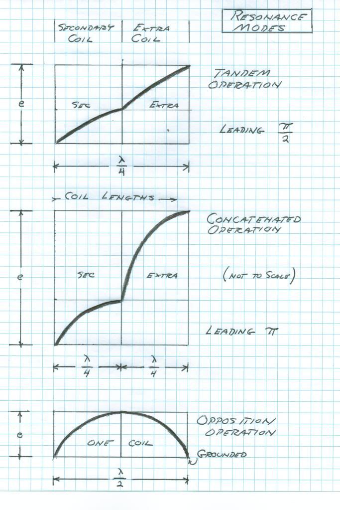
                                CSI sits there waiting for the next stage but haven't quite caught up here and am having a problem in identifying how one can determine whether a device is working in a Tandem or Concatenated manner.
                                Appears I have missed something that could clarify that matter.
                                This is the main reference, also it has the effect of raising the frequency of the secondary.

                                Originally posted by T-rex
                                The secondary winding is the prime mover of this transformer. Here the system operating frequency is established , and then locked in place by a primary resonator. This in itself establishes a telluric transmission network, a basic resonant transformer with a mono-polar connection at the secondary neutral. Another transformer can be constructed, identical in every way except wound in an opposite direction to the first coil. Interlinking the neutrals of these two counter-wound transformers enables a one wire transmission between the two units. This is the basic telluric system. No more is needed than this.

                                The extra coil is employed in order to magnify the potential to much higher values than possible with only a secondary winding*. This however involves ratios of refractions and reflection that are difficult to calculate or even understand. Hence its complications are best avoided in basic telluric testing.

                                *This will increase receiving sensitivity, or "gain"

                                Two modes are possible for extra coil in relation with the secondary coil. Both involve quarter wave resonant rise, this the fundamental of resonant transformation. Its also known as constant potential to constant current transformation. A constant potential is a zero impedance (short circuit) a constant current is a zero admittance (open circuit). Departure from these zero values alters the coil distribution to something other than a quarter wave.

                                This quarter wave can exist in a distinct pair of manifestations. The first mode is when the quarter wave is distributed over the length of both extra and secondary windings as a whole, a pair of eighth waves let us say. This is the TANDEM mode. A multiplication in potential is derived hereby since the extra coil exhibits a higher transmission impedance thereby giving rise to a greater EMF between turns and thus a higher termination potential. All photos of my Bolinas and Integratron setups operated in this mode. It is the easy one to achieve.

                                The second mode of the extra coil and secondary coil connection involves two quarter wave distributions, one on each coil. This is not to be considered a half wave however. This mode is the CONCATENATED connection.It compounds the quarter wave resonant rise of the secondary coil with another quarter wave rise in the extra coil, hence a concatenated resonant rise. This is the holy grail of resonant transformer design and unheard of potentials may be gained in this manner. To derive this analytically is extremely difficult, it is an advance transmission line problem. It might not even be possible to calculate or even achieve this mode of resonance, but we are going to give it a try. Tesla dreamed of this mode but electrical knowledge was in its infancy in Tesla's Colorado years.


                                An excellent addendum to this is the John Miller Paper "Electrical Oscillations in Antennae and Induction Coils" provided with Eric Dollard's paper "Introduction to Dielectric and Magnetic Discharges in Electrical Windings". It can be seen here:

                                http://www.tuks.nl/pdf/Eric_Dollard_...0remake%29.pdf
                                http://www.teslascientific.com/

                                "Knowledge is cosmic. It does not evolve or unfold in man. Man unfolds to an awareness of it. He gradually discovers it." - Walter Russell

                                "Once men died for Truth, but now Truth dies at the hands of men." - Manly P. Hall

                                Comment

                                Working...
                                X