Announcement

Collapse
No announcement yet.

Eric Dollard

Collapse
This is a sticky topic.
X
X
 
  • Filter
  • Time
  • Show
Clear All
new posts

  • lighting the light.

    Originally posted by David G Dawson View Post
    Triode Driver:
    6SN7GTA Triode Driver in parallel works well first up and loud in the headphones.
    Has extended reception distance out to about 5' but no lamps lighting and can even still hear the local Radio Station in the background.
    Went back into Eric's information and come out somewhat overwhelmed by all that he has presented and need to sit back and further digest.
    Using Eric's 110volt HT but notice the specs say 90 volts for 1st Triode and 250 volts for the 2nd and remember him saying he did not have the specs and was working from memory.
    Wondering whether the 110 can't be extended somewhat and not sure why the volts are staggered as a Class A1 amplifier.
    In a TV, both the horizontal and vertical deflection oscillatores are specced at 450 maximum volts and would expect in practice, this would be down graded to about 300 to 400.
    Tuning of the the Function Generator showed the frequency to be very close to secondary design which was encouraging.

    dR-Green,
    Went back through the pages to 40 here but could not find your Driver.
    What are you currently using to light your lamps?
    Thanks.

    Will go back to some basic earlier tests and refine my system as I need to review what I am doing.

    Smokey
    What are you driving, a TC?
    Are you attempting to transmit power to another TC?

    If so, impedance match is important to get maximum power into the primary,, then the coupling to the secondary/extra coil is also critical. If you are using the spiral setup with the strap primary, I think you may have serious issues in this department. It all has to be tuned as a system.

    Comment


    • Originally posted by David G Dawson View Post
      dR-Green,
      Went back through the pages to 40 here but could not find your Driver.
      What are you currently using to light your lamps?
      You mean in the latest pictures? A basic op amp as the output stage. The little black dot in the middle of the green board. The other part is for modulating the signal.


      Tuning has to be quite precise in order to light the filament, it's easy to sweep (frequency) about and not notice anything. This should become easier with more power but then the type of bulb is also an issue, because some light easier than others. They are generally connected like this.

      http://www.teslascientific.com/

      "Knowledge is cosmic. It does not evolve or unfold in man. Man unfolds to an awareness of it. He gradually discovers it." - Walter Russell

      "Once men died for Truth, but now Truth dies at the hands of men." - Manly P. Hall

      Comment


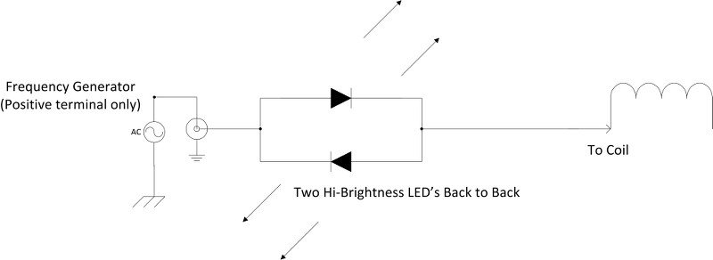
      • Simple LED resonant frequency (TEM) test for coils.

        Obviously the most accurate way of finding the resonant frequency(s) of a coil is to use a frequency generator and an oscilloscope. There is another simple (not-quite as accurate) but it’s a very easy and visual method.

        The circuit below is simply two hi-brightness LED’s connected, (soldered) back to back. One end goes to the signal generator (of sufficient output over the forward voltage of the LED’s), the other end, or test lead goes to the coil under test. Once resonance is achieved BOTH LED’s light up. Tune for maximum brightness of the LED’s and then you have found the resonant frequency (TEM) of the coil.


        Testing my spiral coils I found I achieved resonance at 2.08Mcps, (also confirmed with O-scope) As a secondary resonance check I find that my touch lamp several meters away begins to go nuts and cycles madly (strobes) once resonance is precisely found. Hehe

        Anyway if you haven’t seen this little LED resonance indicator circuit, it’s well worth the few cents to put it together. One can even go fancy and include it in a little box and add BNC connectors & a clip if you want.

        Sputins.
        "Doesn't matter how many times you kick the coyote in the head, it's still gonna eat chickens". - EPD

        Comment


        • Triode Driver MWO

          dr-Green and Sputins,
          Thanks for your responses.
          Yes, have the dual Leds setup and was used on the Hendershot device as a non polarised indicator as this was a flip-flop type of generation, not yet achieved.
          Have a small SWR meter here and may find that also useful.

          cyborg,
          Yes, quite correct and realised after Posting that I needed to take the load resistance into account and for the 6SN7 is about 7,000 ohms.
          Here is where it gets tricky and we need to consider reactance of both L and C and can see an amp meter coming in the Plate circuit as an indicator.
          Have a 1500 pf variable cap in with the fixed 1500 pF and did not see much change with that rotated.
          Yes, we are driving the CSI as a transmitter in an attempt to peak tune the system to measure performace and in particular to measure the half power points and gauge the magnification factor of the Extra Coil and of course, to light lamps at a distance as another indicator.
          Also have the RMR 'Regenerative Magnifying Receiver' (2C22) here which is waiting for testing and should be good for range testing.
          My Extra Coil is different to Erics calculated theory but appears to work and I have my reasons why in previous exchanges.

          Lots of work ahead here I feel as this has not been done before and is only a suggested Driver by Eric and need to now work out the fine details and I started last night by reading my ARRL collections.
          Used the 1N34 pickup head on the secondary and was loud in the headphones and removed the ground lug and all signal disappeared.
          Had a feeling my ground of 6'x4' wire mesh was acting as a receive antenna but not the case but the secondary, by design, probably is as I still hear the local Station in the background.

          Crystal Sets are a bit of an enigma in that most of the designs came out of cities where there was a selection of high powered commercial and national broadcasters at work.
          You only heard from the Country folk on the odd occasion as they were probably limited to one or two stations with some improvement in the dark hours.
          The idea of selecting a design that can power a loudspeaker is simply an indicator to me that it is finely tuned and probably a good basic 'front end' and this is where Moray also began.
          Point here is that we are also using this as a receiver of other 'noise' which can be amplified by an organisation of Vacuum Tubes, again like Moray.

          Today I feel like I am in for a cold and I put this down to the beginning of a detox and this is from being near the CSI while it is radiating from the 6SN7 and an MWO type situation - an active MWO.
          The 'IIC Tubes' device (Iron Inside Copper) gives the same reaction but this is from all of Copper/Iron/Bismuth/Neo Magnets/Crystal Ball and a Mobius Coil, all in and around a long 4' Tube device - a passive MWO.
          Don't think people quite understand this Lakhovsky MWO type effect and this is why Tesla looked into the Health side as he also saw it as an electrical kick start to the Human form and so too George Van Tassel with the Integratron and why Moray sought the Patent only associated with health as they dismissed his energy solution as it was NOT thermionic.

          Feel the Pineal Gland is at work here and this is what has been excited into action and something like the body's computer that needs to be housecleaned where all the detriment can be garbage binned - just an analogy.
          Perhaps we already have our own mini Integratron courtesy of Eric Dollard?
          Want to feel enlightened, just build a Dollard CSI and power it up!
          Lots of indicators here and all meaning lots of work ahead for the electrical experimenter.
          Others need to respond here as to what they feel as after-effects from working near radiating sources - other than electromagnetic - it's different.

          Smokey

          Comment


          • Originally posted by David G Dawson View Post
            Others need to respond here as to what they feel as after-effects from working near radiating sources - other than electromagnetic - it's different.
            Sometimes a brain pain in the front and generally to one side, but most of the time nothing. I wouldn't really associate this with operating the coil but since it's all experimental I keep it in mind as a possibility. But the frequency of this is probably in the region of 1-5% of the time, certainly not consistent enough to make any conclusions so far other than being a coincidence. But seeing as the human body is a nice conductive mass then who knows.

            Possibly some differences in temperature around the extra coil but can't be certain. Hands tend to detune it and stop any effects that may or may not be there.

            Recommended incandescent bulbs for testing:

            MP1MMW - 1.5 Volt - 0.015 Amp
            #40 - 6.3 Volt - 0.15 Amp
            #42 - 3.2 Volt - 0.35 Amp
            #44 - 6.3 Volt - 0.25 Amp
            #46 - 6.3 Volt - 0.25 Amp
            #327 - 28 Volt - 0.04 Amp

            If the filament resistance is too low then nothing will happen, it will be as if the bulb isn't even there. Resonant frequency is very slightly affected by the presence of a bulb, but generally close enough to "normal" to not need any adjustment to get a glow, from there it's easy to fine tune it.
            Last edited by dR-Green; 12-17-2013, 01:13 AM.
            http://www.teslascientific.com/

            "Knowledge is cosmic. It does not evolve or unfold in man. Man unfolds to an awareness of it. He gradually discovers it." - Walter Russell

            "Once men died for Truth, but now Truth dies at the hands of men." - Manly P. Hall

            Comment


            • One thing to remember when experimenting, is that we can strain our neck and
              such things by leaning over he bench for long periods, having a long term neck
              and upper back problem I notice when i experiment too long and in fact I can no
              longer look down at a bench for any real period to do anything much any more.

              I just thought I would mention it as some might not connect the neck strain with
              headaches (they make the head hurt), when it could just be from the act of the
              experimenting and not necessarily the experiment itself.

              Cheers
              Last edited by Farmhand; 12-18-2013, 04:50 AM.

              Comment


              • Health risks

                Here is a chart from the FCC regarding safe exposure to RF.
                The lower the frequency, the safer it is to your health. The low power levels of experiments here are well within the safe range according to the chart.

                FCC_RF_Safety

                There is also a IEEE paper on the subject that goes into detail and calculations, but I didn't think you would want to wade through all that.

                If you are still concerned about exposure, build a Faraday cage around the experiment. At low end HF, chicken wire will suffice.

                OK, now you have no excuses, back to the bench!

                Comment


                • New Subjects Coming

                  Recent events have caused me to take up the subject of Versor Operators. Not long ago there was a public request for me to present what has become known as my “Four Quadrant Theory”. This theory found its origin in Steinmetz’s A.C. book, the chapter “Power & Double Frequency Quantities”. This was a long time back, in the 80s, and I had not thought on the subject since then. At first I was at a loss as how to present an advanced subject to the lay person, but as the momentum grew, I compiled a complete book on the Four Quadrant Versor Operator. Much was learned in compiling this book, and it was my largest undertaking of this kind.

                  My work in Versor Algebra began with a certain insistence by Philo Farnsworth III, son of the television inventor. He knew well of my knowledge in A.C. theory and suggested that I should extend the Steinmetz Method to hyperbolic functions. He handed me a book titled Physics & Mathematics in Electrical Communication by Perrine. Philo never told me why I should do this, but he said “It was the Holy Grail of electrical engineering”.

                  After extensive study on the subject of Versor Algebra, this effort finally led to an equation depicting the propagation on a transformer winding. This provided the wave equation for both the Tesla Transformer and for the Alexanderson Network. Hence, a solid theoretical basis was established for these transmission systems, this founded upon an extension of the Theory of Imaginary Numbers.

                  My work in Time Domain Versors had ended with the paper Symbolic Representation of the Generalized Electric Wave. Space Versor Algebra and the Alexanderson Network have also been my principle efforts. This was applied to my Advance Seismic Warning System, ASW, However, this effort recently was completely destroyed. It was of no interest to anyone and those who “Came to Help”, only assured its fate, so it is history, NO ASW. Gone!

                  It has come to pass that I am engaged in another conflict with the power company. It is not hard these days. This is a bit like the situation at the Richmond Shipyard, which led to the reverse power shutdown at the Richmond Substation. However, unlike then, no equipment is available for such experiments. It is like ASW, it is gone forever. This time everything will have to be done with mathematics. It will spawn in the front seat of the Corolla, like has so much else.

                  The complications with the power company are becoming wide spread. To quote many utility workers, linemen, and switchboard operators, “Lawyers replace engineers”, “Insurance replaces safety”. Bad engineering practices are compounding to the point where a consensus is growing amongst older electrical workers that a conspiracy is in the making. However, it is not one that will be taken up on the Art Bell Show, a cesspool of disinformation. Who cares?

                  The Bell Telephone interests which I am working with at present have requested that I initiate an official inquiry on this matter, specifically relating to the conversion of all distribution systems in America from three wire Delta to four wire wye. This conversion gives rise to harmful consequences, some which seem deliberate. This will be the subject of my next series of writings on the Energetic Forum.

                  This effort, in tandem with the recent completion of my Four Quadrant Book, has initiated my next book. This will be “Versor Algebra as Applied to Polyphase Power Systems”. This will provide me with the theoretical advantage in my official presentation to the governmental power authorities. In writing this book I am coming to some rather amazing realizations with regard to Versor Algebra. I am covering new territory never traveled before. Here the theory of what are called Imaginary Numbers is vastly extended. This material will be put out on the Energetic Forum soon and will serve as an extension of the book Four Quadrant Representation of Electricity.

                  Since David Wittekind and his Gang of Four are forcing me out of my so called “Lab”, and other induced complications, I will be back to Corolla life and have again the opportunity to write new material on the Energetic Forum.

                  73 DE N6KPH
                  SUPPORT ERIC DOLLARD'S WORK AT EPD LABORATORIES, INC.

                  Purchase Eric Dollard's Books & Videos: Eric Dollard Books & Videos
                  Donate by Paypal: Donate to EPD Laboratories

                  Comment


                  • Crystal set Initiative - Tuning

                    Quiet and in need of some action.
                    Sometimes I wonder why I don't take up knitting or crochetry where it is a simple mindless boring routine where you can watch the TV and go insane - not so with Dollard electronics.
                    Went back to the set-up stage and peaked secondary to primary and now have only a 5 to 10mm gap where before I had 40 and had slipped down to 50.
                    The little 50 uA Meter with the 1N34 across the terminals can be used floating at the side of the setup with a short lead attached to the (+) terminal as you don't need a direct attachment for tuning.
                    Magnification factor is still only about 80 from 70 and just realised, the smaller the delta, the better, pointing to a high 'Q'.
                    The 1400pF variable condenser across the 1500pF fixed is tuning the Primary and is about 40% meshed and peak is easy to achieve.
                    Triode Driver adds some distance to the receiver which is now about 2 meters away and with only the pickup head, about 1 meter but notice the probe needs to be pointing at the Extra Coil.


                    Uploaded with ImageShack.us

                    Have placed the required resistors in series with the Plate so that the 6SN7 is looking at the correct load - what this does is raise the HT to about 150 volt for the 110 at Plate and may not be necessary.
                    Still no lamps lit at secondary or extra but am doing this as per the original schematic and fine tuning as I go but Neons light at the primary and especially so between primary and ground and drops the HT accordingly.
                    Lots of radiated energy here but still need to read Eric's detail as he covers a great deal of ground in many Posts including Eric P Dollard Page 13, Post 389 'Notes On Tesla Transceiving 2'.
                    Appears the radiated energy is drawn up the secondary and then surrounds the Extra and I notice my body interference/capacitance has increased and need to stand further back when adjusting.

                    This is a picture of the CSI being driven and have named this a 'Mystery picture' as I am unsure of how it is being manifested - the pickup to the oscilloscope is a 3/4" coil of about 6 turns just dangling in mid air and the black leads are the ground connection but made no difference to the pic connected or not.
                    The circle size changes as you rotate the gain of the sig gen.


                    Uploaded with ImageShack.us

                    While with the oscilloscope shots - this is one from a Tesla Hairpin spark gap and you can see what is going on across the gap.
                    Multiple arcs, about 12 to 15 but the spark you see is a brilliant ball of light but this is what it builds up to as the gap is adjusted.
                    Diffilcult sometimes to grasp a single shot as there are several images here and the connection was made to a metal screw on the wooden support frame.
                    Most of any oscilloscope work here is done through a 500pF Mica condenser or simply from a coil in space or a metal body nearby - too many instances of front ends of scopes being blown due to direct connection.
                    We have literally no idea of what the composition of some of these signals that we are being involved with.
                    Story is that most of the solid-state failures in circuitry is due to inductive kick - 'The Tesla Instant'.


                    Uploaded with ImageShack.us

                    Getting back to basics with the CSI and reviewing all material presented and currently looking at the inductance of the primary and was going to calculate from the Eric P Dollard material that Gestalt presented on Page 13 (Eric's Page 3 circled) but lacking dimensions to use.
                    Quote:
                    Sheet inductance is given by (for primary loop) (A/w)N2 x a Henry.
                    Anybody know of the inductance calculation dimensions for a SHEET Copper Primary? - Thanks.
                    ARRL and Langford-Smith not much help here.

                    Looks like I need to dis-assemble the condenser and go from there and will take pics in the process.

                    Smokey

                    Comment


                    • Originally posted by T-rex View Post

                      Since David Wittekind and his Gang of Four are forcing me out of my so called “Lab”, and other induced complications, I will be back to Corolla life and have again the opportunity to write new material on the Energetic Forum.

                      73 DE N6KPH
                      Why not bring a tape recorder with you into the bushes, and record a regular broadcast?

                      I feel like many people would happily pay to hear a weekly or bi-weekly informal lecture. That regular income might go a long way to buying your OWN lab, free and clear of any "help."

                      Even better would be a two part thing. The first part to be broadcast free to everyone on the Internet, then you say "and now for my subscribers..." and do the second part for paying listeners. There's a radio station out of northern Europe that does this with their interviews, and they're doing pretty well.
                      Last edited by James Barker; 12-21-2013, 08:12 AM. Reason: added idea

                      Comment


                      • Dawson/CSI

                        The first scope pix is a bit of mystery, so I think we need a bit more detail on things, such as :
                        1) what type of "drive" are you using, ie; sine, square, etc
                        2) where is the spark gap? driving the priary of another coil or on the extra coil?
                        3) what are the time/div and voltage settings on the scope?
                        4) are you usung a 1:1 or 10:1 probe?
                        5) what is the scope's rated bandwidth?
                        6) more exact detail of overall experiment setup, preferably in a diagram form.

                        The second pix shows the overlay of two events, which may be cleaned up with some adjustment of the sync and trigger points on the scope. It may also be helpful to increase the v/div so the tops of the "spikes" can be seen.

                        If you are using a spark gap, you should be able to see a short duration damped sine wave after the gap fires when everything is tuned up properly.
                        at slow time/div it will just look like a glitch after the gap fires, when "expanded out" on faster time/div and sync adjustment, the damped sine will be seen, that is, if you have a scope with sufficient BW and a a decent sync section. the sine is >> gap freq.

                        Comment


                        • Originally posted by James Barker View Post
                          Why not bring a tape recorder with you into the bushes, and record a regular broadcast?

                          I feel like many people would happily pay to hear a weekly or bi-weekly informal lecture. That regular income might go a long way to buying your OWN lab, free and clear of any "help."

                          Even better would be a two part thing. The first part to be broadcast free to everyone on the Internet, then you say "and now for my subscribers..." and do the second part for paying listeners. There's a radio station out of northern Europe that does this with their interviews, and they're doing pretty well.
                          That sounds too much like work!

                          Comment


                          • Sheet Pancake Coil

                            Sheet Pancake Coil Calculation:


                            Uploaded with ImageShack.us

                            This comes from R A Ford's 'Tesla Coil Secrets' where I didn't really find any as such.
                            Would have expected the width of the actual Copper sheet to be also included but apparently not and fail to see why.
                            Still going to pull apart for comparison and will measure when free from the condenser.

                            However, what I did find is a Tuning Fork Oscillator using a Carbon microphone which I have several of here and this could be organised for the Hendershot Generator as the 'resonator'.

                            Smokey

                            Comment


                            • copper strip primary

                              Copper strip is a bad idea anyway if you are using HV and gap. The sharp edges will cause corona and losses as well as being more capacitive than that formula would indicate.

                              You would be better off using 5/16 copper tubing.
                              The distance between the pancake and secondary should be adjustable to find the critical coupling point.

                              There, I just gave you more useful info than that book has to offer.
                              Would you like to donate to MY 'paypal" account?

                              Comment


                              • Originally posted by cyborg View Post
                                There, I just gave you more useful info than that book has to offer.
                                Would you like to donate to MY 'paypal" account?
                                Too slow.

                                ..
                                http://www.teslascientific.com/

                                "Knowledge is cosmic. It does not evolve or unfold in man. Man unfolds to an awareness of it. He gradually discovers it." - Walter Russell

                                "Once men died for Truth, but now Truth dies at the hands of men." - Manly P. Hall

                                Comment

                                Working...
                                X