Announcement

Collapse
No announcement yet.

Eric Dollard

Collapse
This is a sticky topic.
X
X
 
  • Filter
  • Time
  • Show
Clear All
new posts

  • Originally posted by Sputins View Post
    @dR-Green,
    Just for clarification, which colour / channel is which? Channel A (Blue) is the underground?

    The radio station transmitter is 100kW and 84.78km away, the overground wave is obviously going to be much stronger because the radio station optimise their transmitter & antenna that way. So their SWR is likely 1. Whereas an optimised Tesla Transmitter wants its SWR as high as possible, so it’s kind of exactly opposite. Nevertheless in theory, the 100kW radio transmitter should have a certain ‘stray’ telluric component. (Sorry for preaching to the choir, you’d know all this already). Imagine if the 100kW station was optimised for the Tesla mode of transmission!

    Likely the chances of getting a strong clean reception for any ‘stray’ telluric component from the station (and to power a load), would be to have a nice ground-stake array. (Not easy or cheap). What is your method(s) of tuning the coil to the station frequency?

    I’ve been eyeing off 1 meter long drill bits at the hardware store for ground rod installation. I could extend the shafts out another meter or more to give two - three meters of depth. Then knock in the copper ground rods. Several of these wired together to form an array. The ground is wet at the moment too. Not sure if my wife will approve of these among her garden though? (I'll have to hide them )!
    Yes Channel A is the underground.

    This is what Eric said in his original post:

    For the diagram shown the coil dimensions are missing, number of turns, etc. A good ground is essential for these kinds of devices. 16 Ground rods in a 10 to 20 foot radius circle, connected to a single ground rod at the center(17th rod), this connection being 10 gauge wire. Dry sand or rock will not ground, so this requires 80, each 14 gauge wires in a 30 foot diameter circle in a star radial configuration, to a center terminal. Without these groundings a Tesla Transformer cannot properly operate, but some "HI-Z" sets may.

    The objective here is to scale the "Crystal Set", a step at a time, into a Tesla Transformer for the reception of medium wave band, 300 - 3000 kilocycle A.M. broadcasts. No license is required for this and the broadcast station provides the power.

    And this objective cooperates with the primary objective. That is; Who will be the first ham to disprove Einstein's theory? An International contest, but who will sponsor it, Iran maybe?

    We have the good fortune in the "Crystal Set Initiative" that, in theory at least, a quarter wave A.M. broadcast tower, and its 120 quarter wave ground radials, must emit a pair of waves as shown by Tesla in his basic diagrams.

    http://i168.photobucket.com/albums/u...slaballoon.jpg

    http://i168.photobucket.com/albums/u...taldiagram.jpg

    Hence it can be seen that a pair of waves are engendered by this transmission system. (Tower and Star Radials). One wave, Hertzian, is the over ground wave, the other wave, Telluric, is the under ground wave. These two waves arrive at the point of reception in their own distinct time frames, giving rise to a difference in phase. Hence, multiple rings of interference patterns are produced. Since the Hertzian portion, over ground, time frame is based upon the velocity of light, then the Telluric portion, under ground, time frame gives the Telluric velocity. Two crystal sets, one over ground, one under ground, and a basic oscilloscope , that simple. I have done this at Landers.

    Concluding, a Tesla Magnification Transformer, properly proportioned can, in theory, actually draw power from a local 50 kW station. Several hundred watts of power reception is likely. This would prove Tesla once and for all. No antenna, just a good ground, and a nice and bright 100 watt light bulb.

    This would overturn physics more than any billion dollar C.E.R.N. project. A ham radio operator overturns Einstein for 100 bucks. What a concept.
    Read,
    Tesla, "The True Wireless"
    Tesla, "System of Concatenated Tuned Circuits"
    Dollard, "System for the Transmission and Reception of Telluric Electric Waves"
    A.R.R.L. "Radio Amatuers Handbook". Chapter "H.F. Transmitters, & Tank Circuits"
    73 DE N6 KPH
    http://www.energeticforum.com/eric-d...tml#post173955

    Also taking a basic Marconi arrangement, apparently the thing is grounded in the same way that the extra coil frequency test is done.


    So apparently it's not "stray" as such.

    Yeah the grounding is not cheap, I calculate it to be about £300 if I use copper pipes of 3 metre lengths and 22mm diameter. The bigger the surface area the better so I'd rather use pipes than thin ground rods. But for economic purposes I've been thinking about iron instead, haven't looked into pricing yet, a quick search on ebay didn't bring up any results so obviously getting hold of iron isn't as easy as copper, so we'll see how that goes. I have the complaint of how a lawnmower is going to tackle my arrangement too so I intend to dig channels for all the connecting parts so the whole thing is invisible. [edit] And maybe plant flowers on top in case the invisibility is too effective to find them again!

    I hear that a hammer action drill is effective at inserting things into the ground, used like a pneumatic hammer.

    High Voltage Lab - Grounding Rods Part 1 - YouTube

    Tuning was originally done like a normal radio, by adjusting the capacitance of the primary, secondary or both, but later with an oscillator and to bring both receivers into phase before proceeding with the tests. But that's not an optimised setup at all, it's "tuned" to the station frequency but whether the tuning balance between the secondary and primary is optimised is another matter. They were both just adjusted to work, nothing fancy.
    Last edited by dR-Green; 07-24-2014, 02:18 AM.
    http://www.teslascientific.com/

    "Knowledge is cosmic. It does not evolve or unfold in man. Man unfolds to an awareness of it. He gradually discovers it." - Walter Russell

    "Once men died for Truth, but now Truth dies at the hands of men." - Manly P. Hall

    Comment


    • Use galvanized iron pipe, its cheap and has threaded couplings along with bolt fitting (flat circular plane with 4 bolt holes) so you can tie it in quite easily to your transmitter. Also, it wont bend as easily while being hammered into the ground like low schedule copper pipe would. Nor do you need to sweat the fitting together, unlike copper pipe. Best of all, it's available in large quantities at your local plumbing shoppe.

      Finally, your better off soaking the ground with water for a day or two and using a maul to pound the posts in or if you have access to an auger use that to drill the holes for your ground rods and back fill with cat litter (bentonite clay) this provides the least earth impedance possible and protects the grounding system from rapid corrosion.
      Last edited by upgradd; 07-24-2014, 07:04 PM.

      Comment


      • Extraluminal Transmission PLUS Lander's VIDEO

        Eric Dollard's NEW RELEASE, includes Landers Video! Sent Thursday, July 24, 2014


        Hi ,

        We are excited to release the presentation that Eric Dollard says is his best one yet! The Extraluminal Transmission Systems of Tesla and Alexanderson is jam packed with 4 hours of priceless teachings from the master himself.

        You will learn not only the history of wireless transmission, but the real science of electrostatic transmission systems that are not restricted to the speed of light. In fact, this is not about "faster than light" but rather INSTANTANEOUS meaning there actually is no velocity! That is why it is called Extraluminal (outside of the speed of light constraints) instead of Superluminal (faster than the speed of light).

        Get your copy now: The Extraluminal Transmission Systems of Tesla and Alexanderson by Eric Dollard

        This science was applied by Tesla and Alexanderson and was used by the US Navy in the famous RCA Bolinas station for ship to shore communication back in WWII. Eric Dollard has improved upon the work of Tesla and Alexanderson in this science and has actually build a full scale working model that demonstrates the principles. The primary application was using this electrostatic antenna system to listen to the Earth signals in order to forecast major earthquakes 24-48 hours ahead of time! The best that conventional science can give us is 30 to 60 seconds, which pales in comparison.

        You will also learn how the electron models and Einstein's science has been erroneously applied to these systems for all these years. And, you will see the truth in a way that has never before been presented.

        SPECIAL BONUS - when you get a copy of this * AMAZING * presentation, you will receive a free bonus download, which is an actual guided tour of the Landers facility, which has never been released to the public before!

        Get your copy now: The Extraluminal Transmission Systems of Tesla and Alexanderson by Eric Dollard

        This presentation is offered at an introductory price, which will expire on July 31, 2014 so make sure to take advantage of this offer now.

        Also, if you haven't had a chance to get your hands on Jim Murray and Paul Babcock's presentation The Secret of Tesla's Power Magnification, make sure to get a copy at the discounted price, which will also expire on July 31, 2014.

        Get it now: The Secret of Tesla's Power Magnification by Jim Murray & Paul Babcock


        Sincerely,
        Aaron @ EricPDollard.com
        Sincerely,
        Aaron Murakami

        Books & Videos https://emediapress.com
        Conference http://energyscienceconference.com
        RPX & MWO http://vril.io

        Comment


        • Concider a handheld transceiver transmitting to someone on the other side of a mountain.
          Lets say that the received signal in S units is very weak or nothing because of the mountain.
          To amuse ourselves we measure the SWR and find the ratio is fair in efficiency for dipole whip.

          Next we try transmit using the ham rig in our toyota corolla and now we are able to barely copy
          a signal on the receiver located on the other side of the mountain.

          Finally we connect a ground wire to the handheld and the signal is received with 4/4 S units.

          Hertzian will say the SWR was improved by the ground and others say the improvement was possible because the earth is able to transmit and receive.

          In this example audio drives an S meter rectifying voltage by means of a diode. When the ground is used the signal is amplified and therefore the audio increases.

          In an example of power transmission through air it depends on how much aluminum you have in the air whereas with earth as an antenna there is considerably more surface area and also subterranean current. The exact mechanism of the amplification is not clear.
          There must be a relationship between aether and telluric is an interaction which Tesla made use of which involved resonance.

          In that relationship is displacement current referred to and not taken into account by Michelson-Morely in the same context.
          Possibly How Maxwell really viewed displacement as in this book 1906 by Math physics department in Italy.

          In every system is an equilibria possibly the pulling of the elastic aether and the rarefaction, compression impressed upon the earth.
          possibly indicated by a brighter light bulb the dark center node in a florescent bulb, reverse SWR of the aether or an S meter gauge or something
          else tells us that what we are doing with telluric has made a definite improvement.
          chatlier.JPG

          Aether well that is something they used to talk about a long time ago why should it be in textbooks?
          https://www.youtube.com/watch?v=yH9vAIdMqng

          Is it that we see birds flying in the clear sky that the earth ground wire should make a difference ?
          https://www.youtube.com/watch?list=P...&v=A49VML0_lEY
          Last edited by mikrovolt; 07-27-2014, 12:37 PM.

          Comment


          • Ground Rods

            Originally posted by dR-Green View Post
            Yeah the grounding is not cheap, I calculate it to be about £300 if I use copper pipes of 3 metre lengths and 22mm diameter. The bigger the surface area the better so I'd rather use pipes than thin ground rods. But for economic purposes I've been thinking about iron instead, haven't looked into pricing yet, a quick search on ebay didn't bring up any results so obviously getting hold of iron isn't as easy as copper, so we'll see how that goes. I have the complaint of how a lawnmower is going to tackle my arrangement too so I intend to dig channels for all the connecting parts so the whole thing is invisible. [edit] And maybe plant flowers on top in case the invisibility is too effective to find them again!

            I hear that a hammer action drill is effective at inserting things into the ground, used like a pneumatic hammer.

            High Voltage Lab - Grounding Rods Part 1 - YouTube
            Thanks for all of the info and ground rod video link.
            I finally managed to watch it. - Amazing to see a 3 meter ground rod installed into the ground in 48 seconds. - Once you have the right method and tools.

            Fortunately I already have a quality hammer drill, not as big as seen in the video, but it should be adequate. I’ll look into as to finding the chuck attachments / adapter for the ground rods. The soil they went into was quite wet and they didn’t strike any rocks. The masonry tipped 1M drill bits may still be required for my ground, in conjunction with the method shown.
            It could potentially be quite important as a portable rig for testing because a ground-rod could be installed with the use of a quality cordless hammer drill within a short time, given the ground that is suitable. Once they’re installed, they’d be real hard to extract again, thus copper thieves would be neutralised, if they could even find them.

            If said installation is as easy as it shows, (or even half as easy), one then thinks about the configuration and depth of the ground-rod arrangement. Or as you point out, Eric says using the star-radial configuration. Sixteen ground rods (two circles of eight), surrounding the central seventeenth rod. (Or a poor-mans’ version with less rods). - The geometry of the rods and depth of each rod could be further experimented with too. I.e. Equal spacing or some other mathematical relationship.
            The hollow rods could be filled with some substance (as previously suggested) to either improve the strength of the ground-rod, improve the connection to the surrounding ground (earth material) or both.

            On the weekend, I bought, sat down and got comfortable to watch the newly released: “The Extraluminal Transmission System of Tesla and Alexanderson” (twice).

            All I can say right now is simply, WOW, OMG!! -I’m still getting over it. - More to follow later!
            Last edited by Sputins; 07-28-2014, 01:35 AM.
            "Doesn't matter how many times you kick the coyote in the head, it's still gonna eat chickens". - EPD

            Comment


            • Vacuum Tubes

              Guy came up on Ebay selling Vacuum Tubes and happened to name his Tester which I dutifully followed up because he had related a minimum for a particular Tube (6AS7).
              His Tester is a Military Hickok type called a TV-7/U:

              http://frank.pocnet.net/instruments/...16-35TV7-5.pdf

              There is more Tube data here which may be of interest for anyone following Tubes and in particular, doing their own testing:

              TV7

              It helps somewhat if you have an indication of what your Tester should be telling you with respect to the quality of any Tube.
              See the minimums recorded on the RHS.
              Now go and look at the Bias required for a 6AS7 and see how it compares to other Tubes.
              Others nominated here are 6Y6, 12B4, 6J6, 6J4, 6336 and 6528.
              The 6AS7 is being nominated by the audiophiles as a headphone amplifier as it is really not an amplifier as such but is superb as a pristine amplifier and probably because of the even harmonic component which makes it so.
              This is from Eric Dollard and his 'grid in - plate out' and 'out of the box' reference to certain Tubes.

              Smokey

              Comment


              • The Beginning

                The beginning of Dr Dollard's presentation: The Extraluminal Transmission System of Tesla and Alexanderson:

                "Okay here we go.. So at any rate Heavyside once mentioned that, let’s see how did he put it.., “if you think my material is hard to read, it was even harder to write”. - Well now we’ve taken that one step further..

                This is going to run through your mind.. Where you have a full PHD level electrical engineering course here; that I had to figure out a way for the layman to understand. And it dammed near killed me to do it.

                So the normal reality for most people is between 12 volts and 110, anyone that dares climb a telephone pole doesn't usually go above the first level of cross arms. We’re going straight for the 12KV.. So here we go.. and I hope I can handle it too". - EPD


                So here Dr Eric Dollard introduces his talk with another unique and clever beginning.. In my opinion: He’s not only talking to the direct audience but also he’s talking to the greater audience, those who have or will buy the video and indeed all of the contributors over the years via the Eric Dollard Channel here on the Energetic Forum. If it damn near killed him to do it, it means that it’s important to him that we try to understand it.

                So go and buy your copy of the video!
                Last edited by Sputins; 08-01-2014, 01:50 AM. Reason: doesn't
                "Doesn't matter how many times you kick the coyote in the head, it's still gonna eat chickens". - EPD

                Comment


                • EPD Quotes:

                  Here are a couple of my favourite (amusing) quotes (written as accurately as I can) from the presentation so far. (@Aaron, I hope you don’t mind).

                  "I came up with one of my NFG parables or Heavyside story about the theory of Electricity. The Theory of Electricity came about in some form, then it was decided that it wasn’t right and it was a bunch of bulk, so then they came up with another theory, so we go by that theory for awhile.. Well lets go back to the old one but a little different, try that one out. Oh that looks great. Then all of a sudden someone lands on the deck and they got the big one, okay and all the rest of the theories go in the garbage can and the big theory is hooted and touted about and all that but then find out you can’t build anything and it doesn’t work but it’s too beautiful , so let’s keep it. But now we have to lie and so we become crazy in our lie and we make the lie a law and we have today’s electrical theory".


                  All the theories are conflicting, Electron theory, Aether theory, Electromagnetic theory , all the theories, they're all basically patchwork, we really don’t know what’s going on. If I went through here, this matrix of people that I see in front of me and asked each and every person what a volt is, there would be an individual answer and none of them would be right. So were going to have to dig our way out of that.


                  So we have this conflicting relativity idea, with space and words of space and parrot talk, and that’s why, you know, I try to be polite but you know the terms people use for things tend to make me want to bare my teeth. - If you want to make me really nasty, you can be a believer of global warming, you will be bitten, not directly by teeth but by the motion of the teeth and the tongue and the larynx ahh, someone will be calling 911. So do not bring it up here… please.


                  Three dimension space, two dimension space, dimension space, dimension space, dimension space, Einstein. There is only one dimension of space and that’s space. That’s how Descartes laid it out and that’s how the whole process works, when we’re going to dealing with this stuff, if we’re going to be defining these particular relationships, there is only one dimension of space.
                  "Doesn't matter how many times you kick the coyote in the head, it's still gonna eat chickens". - EPD

                  Comment


                  • What is an NFG?

                    Comment


                    • Originally posted by Marcus Neuhof View Post
                      What is an NFG?
                      For a NFG explanation, the best thing to do would be to "find all posts made by T-rex" then read the ones with NFG in the title.
                      It will soon become quite clear.

                      Hint: No Good.
                      "Doesn't matter how many times you kick the coyote in the head, it's still gonna eat chickens". - EPD

                      Comment


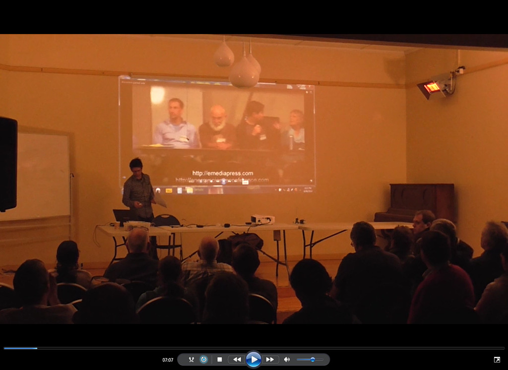
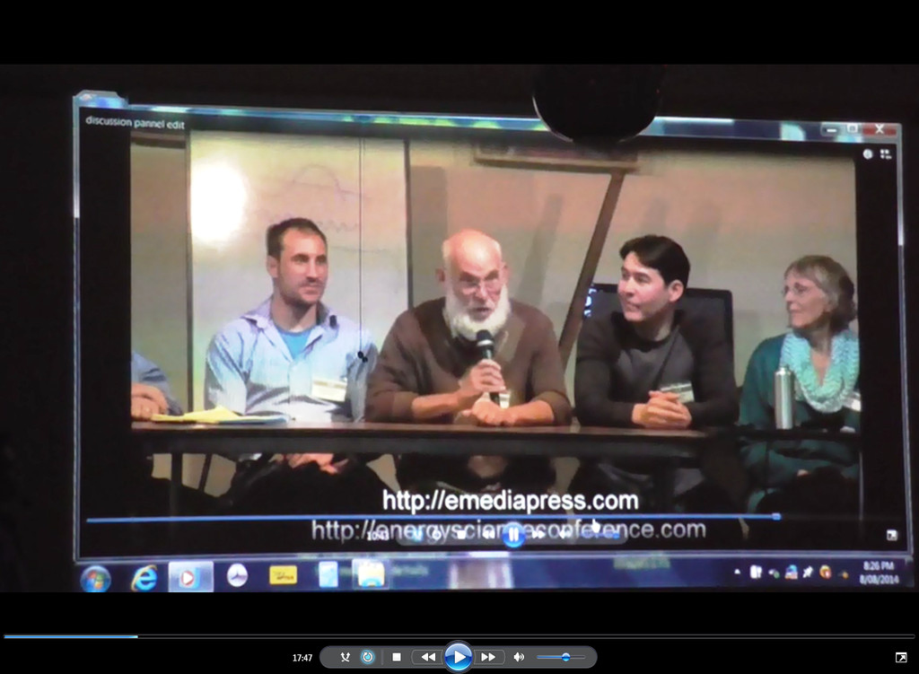
                      • Discussing the Discussion Panel

                        ASTRO SA August 2014

                        Discussing the Discussion Panel at ASTRO SA:


                        Every month I highlight the latest information from Eric Dollard, in my “Eric Dollard Update”. [Yes the little guy at the front is me].

                        All of Eric videos, information, conferences, interviews and releases of his and related people are mentioned, together with sharing my own endeavours. (For the past several years).

                        Generally we have 60 to 80 people are in attendance.


                        It was mentioned to me by many of our members that they thought the positive words of Jim Murray were simply fantastic and inspiring. He is a great speaker in his own right.
                        "Doesn't matter how many times you kick the coyote in the head, it's still gonna eat chickens". - EPD

                        Comment


                        • Is Garrett still around?

                          The equations in his older posts have vanished, such as in this one, " Versor Operators Decoded, With Respect to DC & AC Circuits Pt1":
                          http://www.energeticforum.com/178226-post937.html

                          It would be wonderful if someone had a copy of his posts with the equations in them.

                          Comment


                          • Magnet Truths

                            'Secret Magnet Vortex Revelation' was the source of the following
                            information that was a part of further investigation of the Hendershot
                            Resonator.

                            https://www.youtube.com/watch?v=O1nv0KlbHDM

                            Some magnet designs:

                            https://www.youtube.com/watch?featur...&v=3G-l5Wh2DVY

                            This is a free pdf book on the same subject:

                            https://archive.org/details/magnetism1small

                            There is a considerable series of videos here by the same author.
                            In the pdf book you will find many references to a Mr Nikola Tesla and a Mr Eric P Dollard.

                            Working on the Steven Mark TPU and these types of revelations will most certainly help.

                            Smokey

                            Comment


                            • Garrett's Equations

                              Marcus,
                              Still have all of that information and will pull out for you but may take some time.
                              Later on this.

                              Smokey

                              Comment


                              • Copy Of Post

                                Question On Plank, Q Continued


                                Possibly, the problem I had earlier with the two Power equations for the Impulse discharge lies with the four different measurements of Power (read my prior post):

                                Note: This was written with TEM waves and L & C in mind.

                                Vector Power (Volt-Amperes, Complex Plane Vector Measurement, "the sq root of the sum of the squares" or "Absolute Measurement") Voltmeter reading multiplied by Ammeter reading
                                (eq1)

                                Apparent Power (TOTAL Energy, Re + Im Axis Measurement) Watt-meter reading plus VAR-meter reading
                                (eq2)

                                Active Power (Consumed Energy, Real Axis Measurement) Watt-meter reading
                                (eq3)

                                Reactive Power (Stored Energy, Imaginary Axis Measurement) VAR-meter reading
                                (eq4)

                                I guess the discrepancy is easily seen here, the Volt-Amps (vector power) is what my time based Power equation showed and possibly the second Power equation (no time used) is that of the Apparent Power which is the sum of the Active and Reactive Power. Thus why they are not equal. I guess its back to Steinmetz's books and Heaviside's telegraph equation for me, maybe I will find an answer there.

                                An excellent reference on this subtopic is of course:
                                E. P. Dollard - Symbolic Representation of Alternating Electric Waves [1985]

                                Gotta love that Versor operator, k, in the above book. On that note here's some helpful info on versors (compliments of Wikipedia):

                                In general a Versor can be associated with a plane, an axis and an angle. A versor can also in general be represented by a unique great circle arc. This arc is greater than zero and less than 180 degrees. This is because the shortest distance between any two points of a sphere has a maximum limit of an arc corresponding to 180 degrees.

                                When a versor and a vector which lies in the plane of the versor are multiplied the result is a new vector of the same length but turned by the angle of the versor.

                                When the arc of a versor has the magnitude of a right angle, then it is called a right versor, a right radial or quadrantal versor.

                                That sounds awfully close to what is described as versor, k, in Mr. Dollards book. Some food for thought.

                                Along with the Quadra-Polar nature of Voltage and Current I put together this Diagram which illustrates my earlier point of Voltage and Current not directly representing the Magnetic and Dielectric fields of induction, but merely as they (magnetic and dielectric fields) are seen in varying time with the geometric metallic-dielectric confines of the circuit.

                                Garrett M

                                This is just a Post copy and don't know if the required detail remains intact as you can no longer use the 'Quote' facility as the Forum is closed.

                                Smokey

                                Comment

                                Working...
                                X