Announcement

Collapse
No announcement yet.

Eric Dollard Style Tesla Coil Verses Standard Tesla Coil

Collapse
X
 
  • Filter
  • Time
  • Show
Clear All
new posts

  • Eric Dollard Style Tesla Coil Verses Standard Tesla Coil

    Dear Forum,
    I build a spreadsheet to simplify calculations that Eric provided for building a Cosmic Induction Generator (CIG).

    I was puzzled but not surprised when his calculations came up way different than JavaTC.

    After a bit of messing around I realised they roughly equal the calculated resonant frequency devided by 1 over 2pi.

    For example Eric provided the dimensions for a 1mhz coil. JavaTC calculates the resonant frequency to be 1.467mhz.

    1.467÷(1÷2pi) = 0.93392mhz

    I also did the same calculation using a 20% and 50% primary height with 62% and 10% spacing. The answers were all about 10% out.

    So my question is: what causes these figures to be so different than they should be?

    A coiled wire will not have the same resonant frequency as a straight one of the same length.

    According to JavaTC and my own experience building coils the coil will work poorly using these plans.

    As the primary will oscillate at 1mhz the secondary at 1.4mhz will be 40% detuned.

    So is Eric saying his coil is not a air core resonant transformer with frequency matched coils? If not what principle does it operate by?

    Pancake coils will produce fractals so what is the advantage of trying to build the CIG?

    Also why must the coils be the same diameter. It makes calculation complicated and seems impractical.

    One final comment about the primary coil. I see no advantage in using flat copper strip as the frequency will be below the 10's megahertz range and as the system will be CW so the primary current will be pretty low.

    Cheers!
    -speakerbox

  • #2
    I'm not an expert, but the answer is probably something along the lines of "these coils don't obey traditional electromagnetic physics, that's the whole point of building them after all, so calculation tools that rely on traditional electromagnetic models naturally won't work!"

    Comment


    • #3
      Originally posted by speakerbox View Post
      According to JavaTC and my own experience building coils the coil will work poorly using these plans.
      How do you define working well?

      Originally posted by speakerbox View Post
      So my question is: what causes these figures to be so different than they should be?
      Originally posted by T-rex
      There should not be much left unanswered, it is all in the "Theory of Wireless Power" and "Impulses, Waves and Discharges." But all of this pre-supposes a working knowledge of radio frequency lines and antennae.

      Velocity depends on aspect ratio. If Secondary ratio is 18%, velocity is luminal, this only at 18%. So make the coil 20% and the velocity is a bit faster than luminal. The reason, to compensate for the slowing caused by insulation.

      The secondary is coupled to other coils and capacitance. This lowers the velocity greatly. Thus to compensate the coil wire is shortened by 2/pi=0.63662=63.7% to bring the frequency back up to the proper value.

      As for the extra coil; for a coil aspect ratio of 100% the coil effective velocity is 187% that of luminal velocity (along the coil wire). This coil is burdened down by insulation and gradient rings as well as what little coupling Exists. Thus the coil Wire is lengthened to 157% velocity factor. This is to say, rather than calculating the extra coil on a velocity of 187% that of light along the coil wire to figure the quarter wave, we now instead, in order to compensate for the burden, use a velocity of 157% that of light along the coil wire to figure quarter wave. 157% is equal to pi/2.

      Therefore, secondary 2/pi, extra coil pi/2.

      (Longer Extra)/(Shorter Sec.) = (pi/2)/(2/pi)=pi^2/4=2.465

      Where pi is a correction factor, not an intrinsic mathematical relation. But it may be that by using pi some "magic" resonance may take form. (Experiment and see).
      Originally posted by speakerbox View Post
      As the primary will oscillate at 1mhz the secondary at 1.4mhz will be 40% detuned.


      Originally posted by speakerbox View Post
      Pancake coils will produce fractals so what is the advantage of trying to build the CIG?
      The CIG is a particular configuration and application of the coils, like a pizza is a particular configuration and application of the ingredients. A lone tomato is not a pizza, and likewise a single coil (or two) not connected appropriately is not a CIG.

      Originally posted by speakerbox View Post
      Also why must the coils be the same diameter. It makes calculation complicated and seems impractical.
      Eric's design is based on Tesla's Colorado Springs design. The only way I imagine that it could be complicated is because you have other JavaTC nonsense on your mind. Forget that and use basic calculations.
      http://www.teslascientific.com/

      "Knowledge is cosmic. It does not evolve or unfold in man. Man unfolds to an awareness of it. He gradually discovers it." - Walter Russell

      "Once men died for Truth, but now Truth dies at the hands of men." - Manly P. Hall

      Comment


      • #4
        Dear dr-Green,
        Thank you for taking the time out to answer my questions.

        I define working well as either a very strong E field or sparks equal or double the diametre of the coil.

        The reason why nobody builds Tesla coils with so few turns is they need to be physically large to have a low enough frequency.

        I made a all wood coil form 600mm by 600mm yesterday.

        I will not be able to fit the following guidlines:
        1. 20% of width for height
        2. Conductor diameter
        3. Flat strip secondary 18% width of diametre
        4. Same weight for capacitors and secondary coils

        I will build an Armstron oscillator and see what frequency it performs the best at. Seems as the turns ratio is fixed it will be hard to tune as I can only adjust capacitance in the tank circuit. I will be using Vacuum Capacitors.

        If that fails I will use a spark gap system.

        I will use a 50% aspect ratio and 62% spacing and the frequency will be 1250 kc using a 20 turn secondary.

        Looking forward to seeing the results.

        speakerbox

        Comment


        • #5
          Hi speakerbox.
          Good that you are building stuff.

          Originally posted by speakerbox View Post
          “I define working well as either a very strong E field or sparks equal or double the diameter of the coil”
          Well a ‘working well’ Tesla coil produces no spark at the termination, as this is wasted energy. The output is the neutral terminal, where the displacement current manifests. You use this ‘telluric output’ as a measure as to how well it is working..


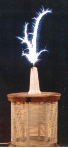
          If you ground your telluric output to the primary coil ground / common ground you will obtain more sparks off the termination. If you are after sparks then it is not the length of the spark it is the quality of the spark! Ideally it would look something like this: Although to produce sparks like in this picture, the CW power would be in-excess of the legal limits! (At least in my country).


          Originally posted by speakerbox View Post
          “ “The reason why nobody builds Tesla coils with so few turns is they need to be physically large to have a low enough frequency”.
          This is one of the reasons why Eric designs for certain ham bands where the frequency is ~2Mhz range and up. (160m, 80m bands).

          Originally posted by speakerbox View Post
          “I will use a 50% aspect ratio and 62% spacing and the frequency will be 1250 kc using a 20 turn secondary”.
          Be careful, isn’t 1250Kc within the AM radio station spectrum!?

          Hope you share your building progresses!
          "Doesn't matter how many times you kick the coyote in the head, it's still gonna eat chickens". - EPD

          Comment


          • #6
            Dear Sputins,
            Thank you for your reply.

            I was lead to believe Tesla Coils don't emit much RF.

            As for your concerns about interference I am not worried. I live 30km from the nearest transmitter. I may use a seperate ground so I don't fry my household electronics though.

            I will probably be looking at 2kw up in power. GU 81ms can handle that for short runs.

            I will post when I am successful.

            -Wil

            Comment


            • #7
              Originally posted by speakerbox View Post
              Dear dr-Green,
              Thank you for taking the time out to answer my questions.

              I define working well as either a very strong E field or sparks equal or double the diametre of the coil.

              The reason why nobody builds Tesla coils with so few turns is they need to be physically large to have a low enough frequency.

              I made a all wood coil form 600mm by 600mm yesterday.

              I will not be able to fit the following guidlines:
              1. 20% of width for height
              2. Conductor diameter
              3. Flat strip secondary 18% width of diametre
              4. Same weight for capacitors and secondary coils

              I will build an Armstron oscillator and see what frequency it performs the best at. Seems as the turns ratio is fixed it will be hard to tune as I can only adjust capacitance in the tank circuit. I will be using Vacuum Capacitors.

              If that fails I will use a spark gap system.

              I will use a 50% aspect ratio and 62% spacing and the frequency will be 1250 kc using a 20 turn secondary.

              Looking forward to seeing the results.

              speakerbox
              As Eric said in the quote above, propagation velocity depends on aspect ratio. For this reason wire length and frequency relations are not reliable to base a design on. You can calculate the approximate frequency quite closely from L and C for any given aspect ratio, as given in the Resonant Circuits bit above. That is, L and C of the secondary coil. The primary is tuned to this frequency. If L is fixed then C can be calculated from the LC constant, or found experimentally (far more easily with variable capacitors than fixed ones).

              LC Constant = LC = 25330/f²

              The CIG is said to not transmit, since each coil is 'transmitting' into the other rather than the earth. But if you are using one coil then with 2kW you will be lit up like a beacon.

              Also as Sputins mentioned, a coil that produces big sparks is not "working well" according to Tesla's definition, in fact quite the opposite since Tesla had a lot of trouble trying to suppress sparks. Being a 'system of transmission of electrical energy', working well means efficient and effective transmission of electrical energy through the system, and not efficiently wasting energy into space with sparks. Although obviously it will produce sparks efficiently almost as a secondary effect if that's the intended application or mode of operation. The thing is not specifically designed in the first place to produce sparks. It's 1/regular "Tesla coil" design.
              http://www.teslascientific.com/

              "Knowledge is cosmic. It does not evolve or unfold in man. Man unfolds to an awareness of it. He gradually discovers it." - Walter Russell

              "Once men died for Truth, but now Truth dies at the hands of men." - Manly P. Hall

              Comment


              • #8
                Dear dR-Green,
                I made a quick spreadsheet to calculate all dimensions of the CIG.

                I copied the extra coil part from the secondary coil calculations as Eric Dollard's "Tentative" calculations didn't make sense.

                All Yellow areas are user input. And it will convert between m, to cm to mm in separate columns. Coil frequency, primary turns, tank cap, secondary and extra coil ratio and spacing ratio are adjustable.

                We don't use inches in Australia so maybe you can add inches and feet etc.

                I added a very rough spiral coil inductance calculator and LC calculator to get a gestimation of the primary cap needed. Saves pounding away on the calculator all day.

                Plus you get to see what frequency is easiest to build to.

                Could you or someone with more experience than me check my calculations?

                If it proves useful maybe we could sticky it somewhere.

                Here it is: https://www.dropbox.com/s/i1kl6apy4e...ator.xlsx?dl=0

                -speakerbox

                Comment


                • #9
                  Dear All,
                  Here is my spreadsheet calculator's output for a 30 turn secondary CIG.

                  The figures match Eric Dollard's ones for a 1000 kc coil.

                  See: https://www.dropbox.com/s/0qyrf2co4y...lator.png?dl=0

                  -speakerbox

                  Comment


                  • #10
                    Originally posted by speakerbox View Post
                    Dear All,
                    Here is my spreadsheet calculator's output for a 30 turn secondary CIG.

                    The figures match Eric Dollard's ones for a 1000 kc coil.

                    See: https://www.dropbox.com/s/0qyrf2co4y...lator.png?dl=0

                    -speakerbox
                    Hey speakerbox

                    What state are you in?
                    I am in Adelaide, South Australia.

                    The spreadsheet is great, although others have made them before. They are certainly helpful for designing coils for a certain frequency and how big it’s going to be. Eric’s calculations on the Secondary are generally very good. The extra coil calcs are only ‘tentative’ - needs work. I would suggest to you to work with the secondary alone at first, add in the extra coil later on. You can achieve most of the effects with the secondary coil alone. - However do as dR green suggests.
                    "Doesn't matter how many times you kick the coyote in the head, it's still gonna eat chickens". - EPD

                    Comment


                    • #11
                      Dear Sputins,
                      I live in Broome, WA.

                      As for the extra coil. I am attracted to this idea of a low turns Tesla Coil because it will allow me to use an extra coil. That's how Tesla got 112 feet long discharges. He got 50kv and increased it to 412kv or so with a Tesla Coil then the extra coil multiplied it by a factor of 30 or so.

                      With a coil of small diameter and great turns it is impractical.

                      I fired up my coil two days ago with a multigap spark gap. Very poor results as I don't have the capacitors needed to attain resonance. it was a 2 to 20 turn system. Got one inch discharges to ground.

                      I am rebuilding it to be 125khz now to utilise the caps I have. It will have 20 to 200 ratio with 0.25mm magnet wire.

                      This will not allow me to use an extra coil though. I need a few hundred metres of coax and a coil form of atleast 1m diameter.

                      Anyhow I will build this one and tune it and then build a larger coil form. I got the feedback system to work using a Armstrong oscillator so it's doable as a VTTC.

                      I mainly want to test whether Eric's calculation work and if it will tune at the frequency he calculates. But with a low frequency coil his calculations come closer to JavaTC (81khz verses 125khz).

                      I don't understand the criticism of solenoid coils. I have got 50cm discharges CW out of a secondary with a 19.5cm wound length.

                      Oh well I will put his system to the test.

                      -speakerbox

                      Comment


                      • #12
                        Originally posted by speakerbox View Post
                        As for the extra coil. I am attracted to this idea of a low turns Tesla Coil because it will allow me to use an extra coil. That's how Tesla got 112 feet long discharges. He got 50kv and increased it to 412kv or so with a Tesla Coil then the extra coil multiplied it by a factor of 30 or so.

                        With a coil of small diameter and great turns it is impractical.
                        Size and frequency is not relevant (to that).

                        e = iZ

                        Or

                        V = IR

                        Z = square root of L/C

                        So once again, size and frequency is not relevant.

                        http://www.energeticforum.com/eric-d...ompendium.html

                        Eric's design is not an exact replica of Tesla's coil, it's slightly modified. If you want to scale that then you will have to refer to CS Notes or use Eric's analysis in the link above. LC ratios will scale, because it's a ratio. Keep it constant. 1:2 = 5:10
                        Last edited by dR-Green; 11-13-2014, 12:52 AM.
                        http://www.teslascientific.com/

                        "Knowledge is cosmic. It does not evolve or unfold in man. Man unfolds to an awareness of it. He gradually discovers it." - Walter Russell

                        "Once men died for Truth, but now Truth dies at the hands of men." - Manly P. Hall

                        Comment


                        • #13
                          Originally posted by speakerbox View Post
                          Dear Sputins,
                          I live in Broome, WA.

                          As for the extra coil. I am attracted to this idea of a low turns Tesla Coil because it will allow me to use an extra coil. That's how Tesla got 112 feet long discharges. He got 50kv and increased it to 412kv or so with a Tesla Coil then the extra coil multiplied it by a factor of 30 or so.

                          With a coil of small diameter and great turns it is impractical.

                          I fired up my coil two days ago with a multigap spark gap. Very poor results as I don't have the capacitors needed to attain resonance. it was a 2 to 20 turn system. Got one inch discharges to ground.

                          I am rebuilding it to be 125khz now to utilise the caps I have. It will have 20 to 200 ratio with 0.25mm magnet wire.

                          This will not allow me to use an extra coil though. I need a few hundred metres of coax and a coil form of atleast 1m diameter.

                          Anyhow I will build this one and tune it and then build a larger coil form. I got the feedback system to work using a Armstrong oscillator so it's doable as a VTTC.

                          I mainly want to test whether Eric's calculation work and if it will tune at the frequency he calculates. But with a low frequency coil his calculations come closer to JavaTC (81khz verses 125khz).

                          I don't understand the criticism of solenoid coils. I have got 50cm discharges CW out of a secondary with a 19.5cm wound length.

                          Oh well I will put his system to the test.

                          -speakerbox
                          Okay wow Broome! It’s one of the most remote, arid yet beautiful coastal locations on Earth. (Or so it’s said, I haven’t been there as yet. - One day a family holiday / fishing trip is in order, but then I won’t want to leave).

                          I shouldn’t think you’ll have too many inspectors knocking on the door concerned about your coils up there, although hams world-wide can still detect transmissions if operating on their frequencies.
                          It would be nice to see pictures of your Armstrong oscillator and coil setup when its ready.

                          Study the material from Eric, Dr-Green & Jpolakow. The coils are built with minimal dielectric material, (Ie no PVC or cardboard pipes), they are built to certain aspect ratios and certain space windings. It all about the combined electrical speed of propagation, not necessarily the length of the spark, but its the quality and propagation. It’s also about the displacement current aspect.
                          "Doesn't matter how many times you kick the coyote in the head, it's still gonna eat chickens". - EPD

                          Comment


                          • #14
                            Dear Sputins,
                            Yes it is a beautiful spot!

                            I finished the coil last night at tuned it to 128khz and 80khz.

                            The JavaTC and Dollard calculated frequencies.

                            The output was very poor and I don't see much point in further building or experimenting.

                            From experience I see two problems:
                            1. magnetic flux density is too low and coupling too loose due to the size of the primary.
                            2. primary and secondary coupling is too low due to coil arrangements
                            3. design requirements are nonsensical and stringent

                            I am not a engineer, these are my personal opinions I give as explanation why I am discontinuing my efforts.

                            I will go back to tube coils and try a bipolar arrangement or two coils 180 degrees out of phase.

                            Anyhow I gave it a go and it's time to move on.

                            I didn't witness any strange phenomenon and cranked the power past 2kw. The rf was higher than a normal TC but the dielectric field was weak.

                            I have produced very powerful dielectric fields and fractal like gas discharges with a tube coil as seen here: crazy rf from tesla coil - YouTube

                            Good luck to all.

                            -Wil

                            Comment


                            • #15
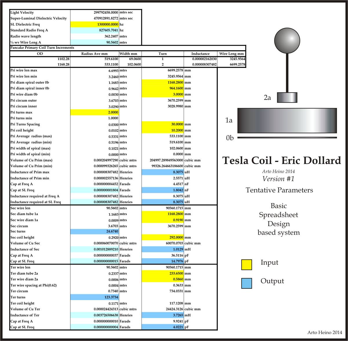
                              Spreadsheet Version #1

                              I hope this set of Erics parameters show the clear minded design that Eric has given us. These sizes are whats been stated in all the pages presented so far.

                              I adapted this spreadsheet from my large coil project I did in 2012, the spreadsheet design worked great. I never needed to use any Tesla Coil program as I was not looking for a sparking coil based on RF, but a transmission coil based on non radiative principals(Tesla Longitudinal Wave). The unit I built worked as designed, I detuned the top load just enough to get 3ft streamers from a 1 kw power source, it also gave very nice glow with no discharges as I tuned it to finally give no sparks and only a slight glow indicating high efficiency. The reason to detune the top load was to see how much charge was being stored, thus a breakout would indicate this, where proper tuning would eliminate any such sparks, which is the CORRECT way of understanding the TMT Coil. The coil I made was not based on Eric design sizes but as you can see I used Erics directives to get the correct ratios and parameters. I will release the spreadsheet as soon as I finalize version #4. I hope this helps, regards Arto.

                              Comment

                              Working...
                              X