Announcement

Collapse
No announcement yet.

Peter, whatever happened with Eric P. Dollard?

Collapse
This topic is closed.
X
This is a sticky topic.
X
X
 
  • Filter
  • Time
  • Show
Clear All
new posts

  • Kokomoj0
    replied
    Originally posted by T-rex View Post
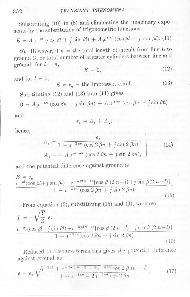
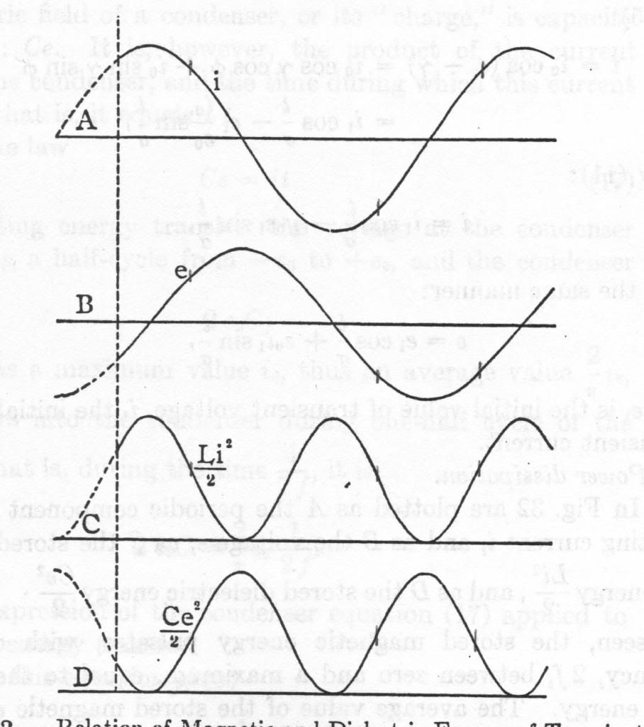
    From "Electric Waves, Discharges, and Impulses", C.P Steinmetz, p67

    Relation of Magnetic and Dielectric Energy Transient


    @Eric

    When building a TMT where should we place the nodes and how many are optimum for proper operation? The phase angles for each of the coils?

    I presume that could easily be accomplished by measuring the reflected voltage for each coil or even using an swr meter between them to zero in?

    From what I gather it sounds like odd number 1/4 lamda, 3/4. 5/4 and so forth for the total? I believe the patent stated the whole thing should be 1/4 and I presume swr = 1 at the ground side.

    I would think that 1/4 lambda for the whole thing would present some interesting tuning hurdles for self resonant coils. not sure if I am making sense here.
    Leave a comment:


  • madhatter
    replied
    Eric, another couple questions. The use of coax cable and inter turn capacitance.
    Basically given the feature of interturn capacitance of the flat wire Tesla used in the primary, if using coax cable; being sheathed in teflon and thus a good dielectric it's increasing the capacitance over air, how does this effect the LC of the coil? also since coax cable suppresses inductance is this by design as needed to enhance the longitudinal wave? Then also wouldn't that mean that the secondary is not mutually inductive but reactive via capacitance?

    Is there a similar phenomenon to current voltage lead/lag phase occurring in the inter turn capacitance?

    This is also why the mass of the conductor is critical to being matched right? is there more of a correlation to the material? copper vs silver etc.. Do you think there is a correlation to the materials affected by transmitted vs reflected rays and if a material that is more affected by transmitted rays being more conductive to transmitting longitudinal waves

    Leave a comment:


  • amigo
    replied
    That's what I'm talking about , the Cosmic Induction Generator post was awesome with all the original photos.

    Blows out of the water all the Tesla Coil wannabe builders and them some!

    Leave a comment:


  • Farmhand
    replied
    I was wondering if I could get some clarification of the text below from this patent. What does it mean ?

    Patent US1119732 - ELECTRICAL ENERGY - Google Patents


    Uploaded with ImageShack.us

    Nice arc and plasma displays by the way.

    Cheers

    Leave a comment:


  • jpolakow
    replied
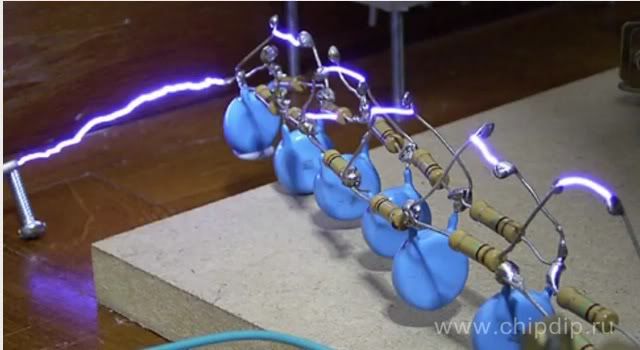
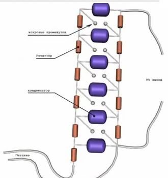
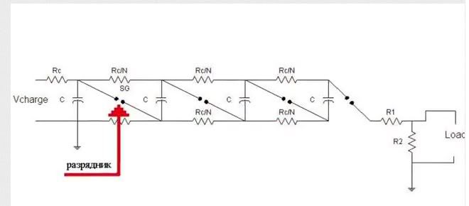
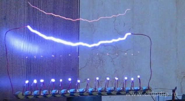
    Eric asked me to include this here. Is is from the Charge Conserving Capacitive Spring Thread. It is of a Marx Generator:

    Here are some photos of capacitors charged in parallel, discharged in series. A distributed dielectric gradient automatically operates the spark gaps.


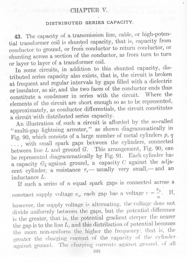
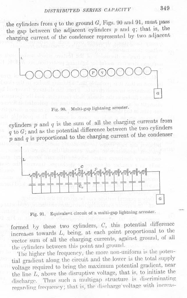
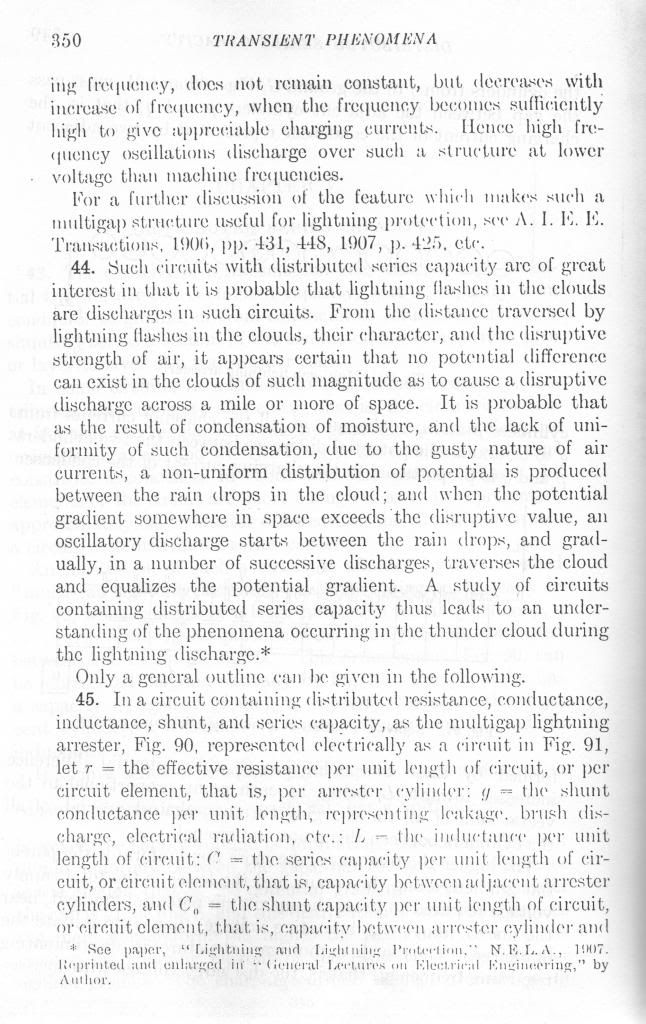
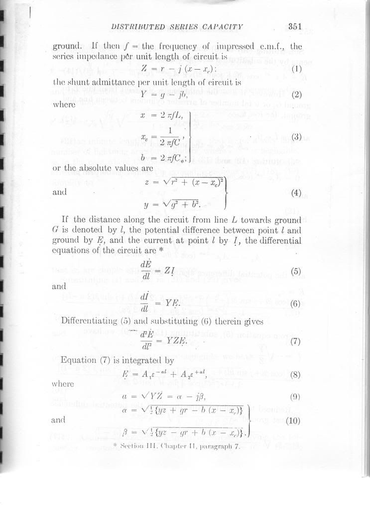
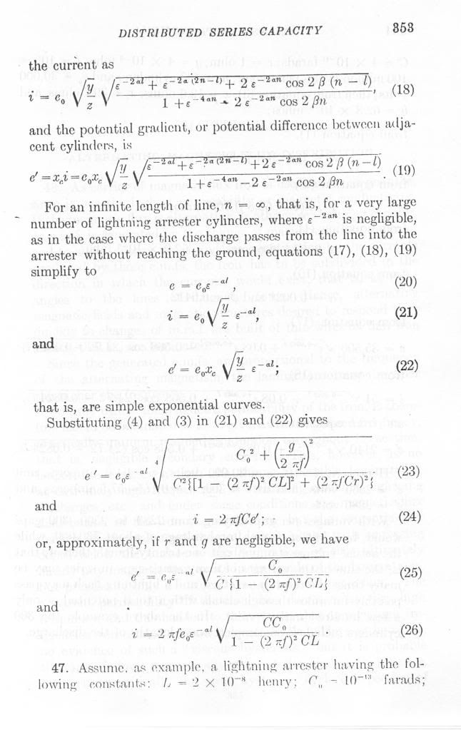
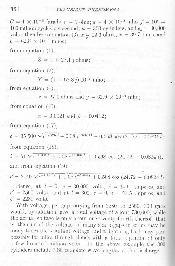
    And the following from Steinmetz, "Theory and Calculation of Transient Electric Phenomena and Oscillations".


    Leave a comment:


  • Gestalt
    replied
    The Cosmic Induction Generator is truly fascinating. It really seems to show the fractal nature of reality. Planets and comets appearing...I wonder what else it would show. I am curious as to what the original purpose was in constructing it? Is that pure dielectric energy forming inside the bulb?

    Leave a comment:


  • jpolakow
    replied
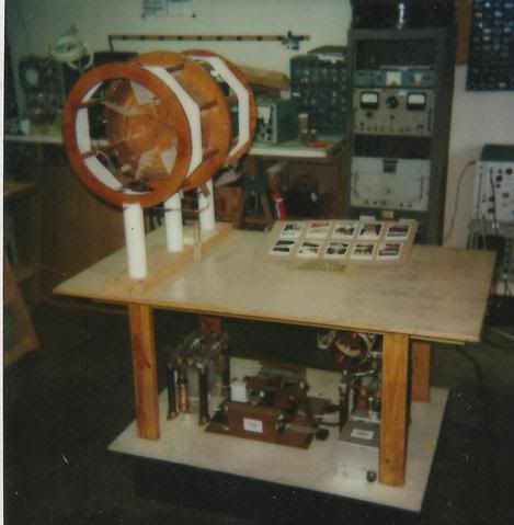
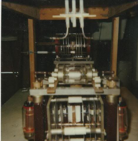
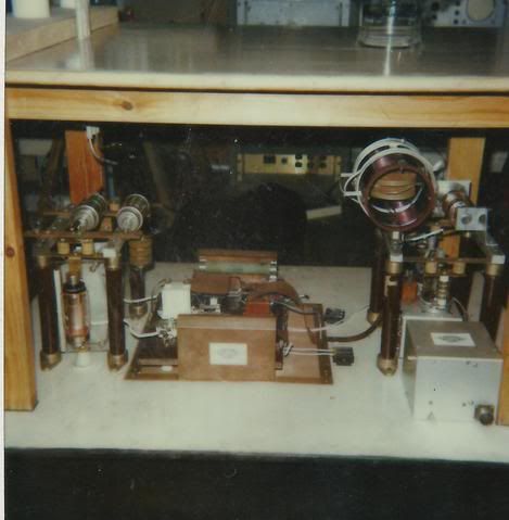
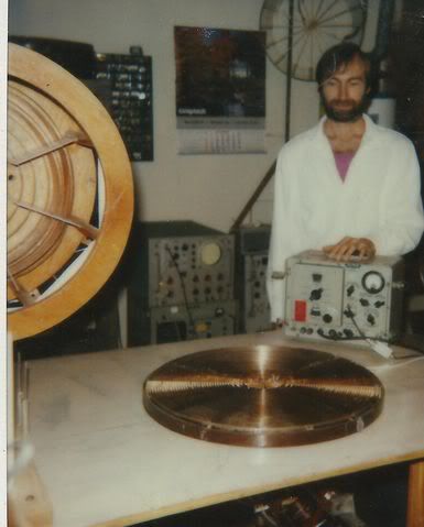
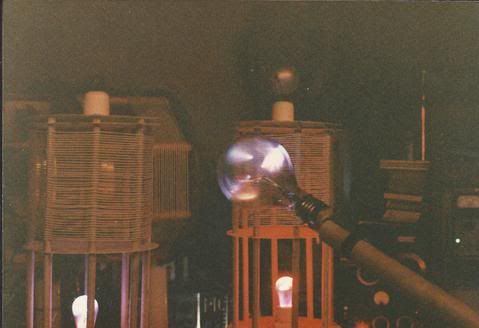
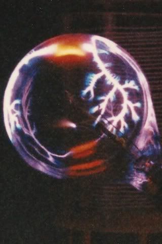
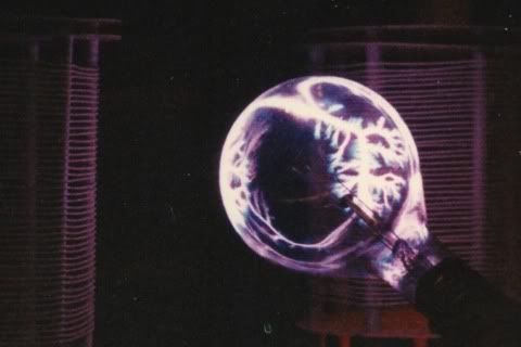
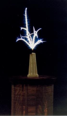
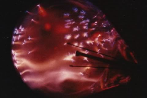
    These pictures are from a Cosmic Induction Generator, that Eric Dollard built. Everything you see in the pictures was built by Eric's hand, and his assistants: Donald Lockwood of the Integraton and Michael Knotts. It was so named the "Cosmic Induction Generator" because it created "galaxies" through electric induction. (That's why the Farnsworth family adopted Eric)

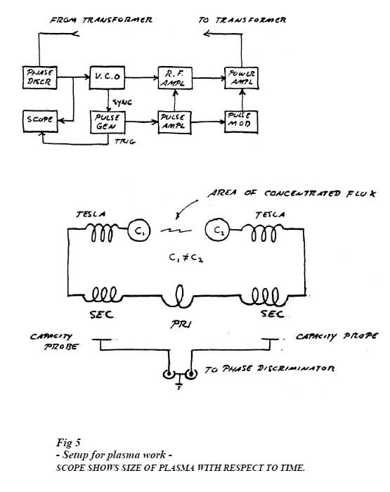
    It was a balanced field generator using Tesla Transformers. A burned out, incandescent light bulb was held in between the dielectric field of the out of phase extra coils. On page 15 of "Condensed Intro to Tesla Transformers" it is labeled the "area of concentrated flux." The out of phase extra coils create the central plane of superimposition from which the galaxies emerge. Everything is golden ratio, five phase fractal.

    Comment from Eric accompanies the pictures.


    The first picture is a schematic of the setup. It is from page 15 of "Condensed Intro to Tesla Transformers"


    This is a blueprint of the coils, all arranged in a line. In the pictures the extra coils are separated, sitting on stands. The diagram is an exact blueprint for the number of turns. The primary details are not easy to see. Only the outside winding of the primary is visible. It was probably 2 or 3 turns, can't remember.


    Primary and Secondary Coils:


    Power Supply: 10 kw vaccum tube high frequency power supply. 10,000 volts 1 ampere 2500 kilocycles


    High Frequency Power supply, tubes missing from their sockets, tubes were 4 Eimac 304-TL pulse triodes from WWII radars EImac 304 TL and 304 TH power triodes represent a most effective device for producing high frequency pulses of extraordinary power


    End view of primary and secondary. Note internal spiral windings are the primary. Experimental coil lays on the table


    Extra coils are on legs, the primary and secondary coils are in the background. The bulb is held in between the two extra coils.


    Note zone of cosmic superimposition, the orange "flamey" region this is where the creation begins. Note directly below it a comet is moving from left to right. Directly below that a streamer changing from violet to red in another cosmic superimposition . Hence a plane of cosmic superimposition passes through the center of the bulb. Here is where the galaxies are born.


    Note the fractal pattern on the glass - no one else's Tesla coil does this!


    Fractal, golden ratio discharge into counterspace from extra coil. Golly Mr. Wizard why does it look just like Colorado Springs?


    The red spot of Jupiter in a burned out incandescent light bulb. The light bulbs were from the L.A. Departent of Water and Power.


    All the equipment in the photographs were embezzled by George Flores in Los Angeles California. He was someone else that showed up to "help" Eric Dollard. Everyone wants to help "themselves" to Eric. Like the martians in the movie "Mars Attacks" -the aliens were announcing "We are your friends" as they start exterminating the humans.

    Borderlands embezzled all the funds for the safe place to move the equipemt to. The funds were sent by Josh reynolds. Eric was told "We need the money more than you do".

    Leave a comment:


  • SilverToGold
    replied
    Hi Eric, I'm fascinated by the hollow Earth theory.

    I would be interested in how you came to your conclusion on the hollow Earth? Was it from your work in Telluric waves?

    Thanks for all your work, I'm intently listening to you and respect your hard gained insights. It's rare to hear the truth these days and when it's heard, it rings a bell within those similar souls while scaring those opposed to truth.

    The coyote roars and who will listen?


    Originally posted by T-rex View Post
    How deep should you go? To the center of the earth- but what are you gonna do? (the earth is hollow).

    Leave a comment:


  • t-rex
    replied
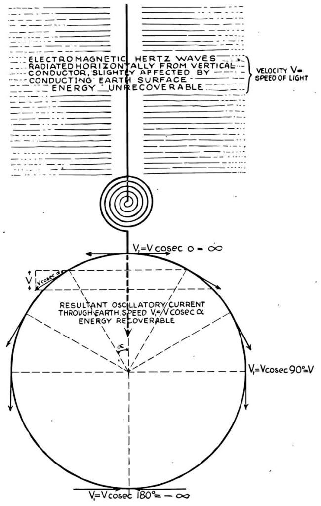
    Tesla's Diagram of overground vs underground waves Hetzian/Telluric

    Tesla's Diagram of overground vs underground waves Hetzian/Telluric

    Note Telluric velocity, a function of angle around the earth, it is a cosecant, infinity at the poles, luminal at the equator. Pi over two is the integral "velocity"


    Leave a comment:


  • t-rex
    replied


    Leave a comment:


  • t-rex
    replied
    Originally posted by Lambda View Post
    Greetings Eric and the Group,

    I've been lurking on the EG forum for some time, but am the one who posted the photos of your "Cosmic Induction Generator" as well as the plasma in the burnt out street lights that generated galaxies and marine life-like manifestations that Tom Brown gave to me in the yahoo group some time ago. I've learned an astonishing amount of information from your posts Mr. T-Rex and really appreciate you taking us under your "paw" and teaching us. I want to assure you that you are NOT wasting your time, good things will come of this! I promise to do my very best and will do whatever it takes to attempt to build a working TMT!

    I wanted to inquire about something that Gerry Vassilatos wrote in his "Secrets of Cold War Technology" book, on page 32 he mentions the pulsating DC with "no reversals of any kind allowed", but if I understand correctly, your TMT generates Oscillating Currents, which would go below the zero volts line, as you describe in your video with Chris Carson about 9 minutes into it when describing the impulse wave as well as the oscillating current wave, which you state was the one utilized by Tesla. According to the writings and researches of Mr. Vassilatos, I get the impression that Tesla was utilizing the impulse wave and that this is when the "real magic" happened, but you state your TMT utilizes the oscillating current wave form. I just wanted to have a complete understanding if possible. I obviously believe the man who has built the apparatus, the true Tesla Transformer, and believe you 100%. Can you give any insight on the usefulness of the impulse wave and if Tesla used it and how? I'm simply looking for clarification if and what application this impulse wave was utilized.

    I am an avid ham operator and have built my own Tesla coil (the type you refer to as the cardboard tube variety, although I used 4" PVC) and have also built the "Hairpin circuit", which does shatter ohms law as far as I understand it. I still cannot explain or understand why that hairpin circuit lights a 300 watt halogen bulb even with the circuit being shorted across the bulb. I have gathered all of the necessary parts to build the pancake coils arrangement and am working on that now since I finally have my own house and a pole barn that is my new lab. After the pancake coil I intend to replicate the TMT if it takes me the rest of my life, but am shooting for this spring / summer.

    I built a crystal radio back in 2006 that utilized a germanium diode (as they take 0.3 volts to forward bias rather than the 0.7 volts required of a standard silicon diode), and used a high impedance piezo transducer glued to a funnel rather than high impedance headphones, and I could literally hear that radio on the other side of the house, it was very impressive indeed! It was connected to a good 8' ground rod and a center fed 102' wire dipole (at my previous residence). Living in Illinois SW of Chicago, WLS has a very strong signal here at 890 kilocycles / second.

    I've donated in the past and will have another donation on the way in a few days. Again, thank you for all your hard work doing the writing and thanks to jpolakow for everything he is doing getting the information on the net.

    Where I live now, I have a 56' free standing tower with a tri-band yagi and wire antennas which go down to 160 meters, but it is nearly pure sand here, and although I have 4 X 8' ground rods pounded in at the tower, which seems to work great for conventional transverse wave RF communications, I know I need to do much better than that to get the intense ground system you speak of to continue in the right path.

    Again, thank you and jpolakow for all the hard work to keep the great information flowing! Everyday I look forward to all the new posts and the new information to absorb!

    73 DE WX9HV (previously KB9UBZ)
    Impulse currents are for vacuum tube work. Sinusoidal currents are for radio or power work. The aluminum cathodes in Tesla's tubes are aluminum for a reason. Aluminum is a secondary emissive cathode, and the oscillatory nature of the transient causes a multipactor action at this cathode. But the wave must be offset like an impulse. An external D.C. supply may work.

    I may say that Vassilatos seems to be "channeling" his information so be cautious with his theoretical ideas that involves details. His work is more important for the layman. And, his Vril books helped me greatly!

    Leave a comment:


  • Gestalt
    replied
    Additional Source for Eric Dollard's Latest Writings

    I have put together many of the posts Eric Dollard has in this thread for myself and those who want to catch up and want it all in one place, up on my website. I figure the more exposure Eric's work gets, the better.

    Eric Dollard » Gestalt Reality

    1. "Energy Defined" by E.P.Dollard
    2. “The Theory of Anti-Relativity” by E.P. Dollard
    3. “Metrical Dimensional Relations of the Aether” by E.P.Dollard
    4. Additional Posts by E.P.Dollard

    I am slowly reading through all of Eric's work and compiling notes and resources as well. Hope to add personal visual drawings in the future also.
    Last edited by Gestalt; 01-10-2012, 03:45 PM.

    Leave a comment:


  • t-rex
    replied
    Originally posted by Sputins View Post

    Also mentioned in another video you said, “Any effective conductor of radio frequency current has to be a third wide as it is long, can’t be any thinner”. – I take that as meaning the conductor for the output of the extra coil, connected to our ground (output) Ie, the displacement current into the earth, connected to the heavy ground connection.
    Correct for the interconnecting leads, which connect things together particularly the ground connection. You cant have a good ground unless the connecting lead is this shape, otherwise it becomes inductance which becomes a parasitic energy flow


    Originally posted by Sputins View Post
    Ok, I understand. What about the length of the ground rods? How deep? (Deeper the better I would guess). What about the ground rod material itself? Copper rod? Or would galvanized rod / pipe be adequate here?
    How deep should you go? To the center of the earth- but what are you gonna do? (the earth is hollow). The material of the ground rod should be copper ideally. It should be copper of a large surface area. All inter-connections should be SOLDERED.

    Originally posted by Sputins View Post
    Would I be correct in saying the close wound PVC / Cardboard Tube variety of coil, made popular by most so called “Tesla coil builders” are made for arcs and sparks or in “display mode” only. The arcs burst from the elevated capacitance (toroid) (NOT THE CORRECT OUTPUT) and all the energy is all wasted into the air. (90%) Where the system should be designed not to radiate at all..
    Yes

    Leave a comment:


  • madhatter
    replied
    Originally posted by T-rex View Post
    The receiver consumes power from the transmitter, it would show on the plate current meter if large enough. It's not free.
    I did a quick check of the socal area and there is an AM station at the southern border pumping out 77,000 watts daily. I'm designing around that frequency to harness the power.

    Going over referenced material, it would seem that the best arrangement would be more of a radionic antenna. a grounded antenna plane to best capture the 90% power waves, correct? the radiated "air waves" should be the far weaker ones to the longitudinal ground wave.

    I've been playing with the single path TM circular wave guide and it seems that type of arrangement for resonance may be best with the shunted ground or now in this case air lead, for some reason it seems that for this exercise the reverse arrangement would be whats needed

    Leave a comment:


  • t-rex
    replied
    Originally posted by Sputins View Post
    T-Rex - Firstly, thank you for your earlier reply to my TMT question. I very much appreciate the advice and the answers given.

    As shown in the old Borderlands video’s the extra coils constructed by Eric generally are not of the Cardboard / PVC Tube style geometry.

    So the more correct geometric form(s) resemble either a flat spiral coil, or space wound extra-coil of equal height to diameter ratio with approximately 100 turns?

    Most of your (extra) coils are constructed from coaxial cable, (which was invented by Oliver Heaviside)! You mention that the inner most wire is never used, and that only the outside shielding is used, (due to the skin effect). The inner wire acts more like a reflector. (See Tesla’s Longitudinal Electricity Video & “Fallacies of Conductors” by Eric P Dollard).

    The Teflon insulated coaxial cable used, I would guess from looking at the video that the coaxial cable used is RG178 or RG179 Is that correct? Is any PTFE / silver-plated copper coax cable ok for these types of coils?
    Thirty turns are about right on the extra coil.Any teflon covered co-axial cable is fine, but remember the copper weight of the primary, secondary, and extra coil MUST all be equal, this is important. Metal lost to the "skin effect" must be taken into consideration. Rule:
    2 inch thick 60 cycle, .2 inch thick 6000 cycle, thickness inverse to the square root of the frequency (flat stock is best)

    Leave a comment:

Working...
X