And in The Beginning, Versors (1 of 3)
(I) What of this thing called versors, and why is it that we should be interested in them? In the most basic conception a versor operator is a means to “move about” in a given dimension or dimensional relation. In an extended conception a versor operator is a means of moving from one dimension into another dimension. In the most general conception versor algebra is the algebra of position.
In nature there exists the four polar positions of our moon. This gives four unit versor positions,
, new, conjunction
, leading, quadrature
, full, opposition
, lagging, quadrature
Hence the Lunar Versor operator,
(1)
These unit versor positions occur when at a given geographic location the following exact relations exist;
Full, moonrise at sunset
Lead, moonrise at noon
New, moonrise at sunrise
Lag, moonrise at midnight
This leads to a versor algebraic expression. Hence a natural set of versor relations in quadrapolar form. It should be noted that Nikola Tesla’s original archetypal vision of alternate electric waves was his poetic versor rotation of the Sun-Earth relation. Needless to say versor algebra finds extensive application in alternating current theory. Read first part “Symmetrical Components” by Wagner and “Power and Double Frequency Quantities” by Steinmetz, (from his A.C. book), for advanced concepts.
A most important application of versor algebra is the study of complex electric waves in space. There has been no progress beyond the cumbersome and under-developed quaternions of J.C. Maxwell, nor the transverse electromagnetic vector algebra of Oliver Heaviside. This is an important task. Such an electrical condition is found in the propagation of electric waves within transformer windings. The networks of Nikola Tesla and Ernst Alexanderson follow from an analysis of complex electric waves in the common transformer. However this knowledge evades us. It is that the present state of versor algebra has not developed out of its infant form, the square root of negative one. It’s engineering application was founded by C.P. Steinmetz (1898 A.D.) and he also suggested higher order versors as given in his A.C. book, “Roots of The Unit”, and etc. Steinmetz however never applied these to engineering even though their possible application was evident. He later on became rather “stuck up” on his own established work, this a side effect of G.E. using Steinmetz to promote their own image. A more generalized conception of versor algebra was attempted by Alexanderson McFarlane but this also never developed into any engineering applications. This is where versor algebra sits today.
(II) The concept of a versor algebra is not new, nor is it limited to electro-dynamics. One of the oldest versor systems is the symbolic representations of the Aboriginals (Indians) of the American Continent. These systems found advanced development in the cultures of Central America. Noteworthy here is the “Mayan Calendar”. In versor symbols this calendar states,
For unit,
And it is nearing the time
unit,
Where m is an unknown unit division in a grand cosmic cycle of
years.
This in common language, equation one states “Happy Grand New Year”. A versor axis, here given as , raised to a zero power, is like midnight, or the new moon, it is the start of a “new day”.
In mechanics there exists the condition called “top dead center”. In electrics there exists the condition called “unity power factor”. In both cases it is a vertical reference, zero degrees, pointing upward. This is expressed by “high noon” on the face of the clock. This hereby establishes the position of a reference versor,
(2) unit
(III) Another versor system of antiquity is that developed by Pythagoras of Ancient Greece (570 - 495 B.C.) This system is called “Music”. It is based upon the HARMONIC SUBDIVSIONS of an oscillating string, two to one, two to three, four to five, and etc. Each subdivision represents a versor position. This developed into a base seven versor,
(3)
It is however than n is a fractional and sometimes complex quantity. Therefore music represents a most complex versor system. This versor algebra, or music, found slow development until the era leading to Martin Luther, 1400 A.D. – 1500 A.D. The foremost development of this era is what are known as the “Church Modes”
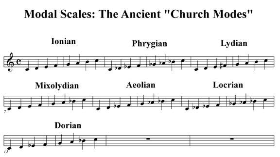
It is of interest to note that one Church Mode in particular has a hysteresis loop. The rising scale takes a different path of notes than that path of notes for a descending scale. Here exists a musical analog of a hysteresis cycle. M. Luther (1500 A.D.) published his archetypal musical series using the Church Modes. Of these, his “Ein Fest Burg”, is well known in church music today, it is the “standard”.
After 1600 A.D. music found considerable advancement in Italy, mostly thru the efforts of the Italian Priest, Antonio Vivaldi. (1678 – 1741 A.D.) From here forward the use of the church modes was confined to only two out of the complete group. Today these are known as the MAJOR scale, and as the MINOR scale. Transformation between frames of reference known as “keys” (the frequency bands) was not possible until the system of “Equal Temperament” by J.S. Bach (1700 A.D.). Bach’s versor system was based upon the expression
percent.
This gave one unified versor system of divisions called the chromatic scale. This twelfth root relation is the basis for the diatonic scale of today. It is however that Equal Temperament is at odds with the original percentages, or ratios, of the Pythagorean System. This remains as an unsolved condition in the versor algebra called music.
Announcement
Collapse
No announcement yet.
Peter, whatever happened with Eric P. Dollard?
Collapse
This topic is closed.
X
This is a sticky topic.
X
X
-
Pointless Posts
To "LOUD" and "Bill Jensen"
LOUD,
I don't think posting about a Bedini device in an Eric Dollard thread is a smart idea for many reasons, although you may have thought the topic you brought up was "teslian" and therefore kosher to post here.
In reality it was "Peter Lindemann/John Bedini-ish" which isn't whats being discussed on THIS THREAD. I'm sure your post would be a great contribution to a thread that pertains to what you were discussing, but sadly its not this one.
I have read almost all of Tesla's original works and have NEVER HEARD OF COLD ELECTRICITY (from him), he does make reference to the NATURAL MEDIUM the AMBIENT MEDIUM and to a "RADIANT ENERGY" which make sense when you hear it from TESLA. What John Bedini says isn't what Tesla says, John only references a book by Gerry Vassalitos that then talks about Tesla, he then only uses catch phrases that point to Tesla like "Radiant Energy". At the end-of-the-day John's device is an IMPULSE OSCILLATOR. This device's output signal is very interesting but DON'T FOOL YOURSELF into thinking that its output is what Tesla was referring to when he said "Radiant Energy".
IMPULSES are what Tesla was INPUTTING into SOME of his various apparatus', all Johns device does is give you what Tesla was using to DRIVE those various apparatus with. So it would follow that impulses alone are not the TRUE "radiant energy". Tesla created a TWO wire to ONE wire TRANSFORMER (that can use IMPULSES on the input) to SEND ENERGY across space as if distance was non-existant, rendering the receiver and transmitter as one. (Lets see that with HERTZIAN WAVES, oh wait, "square of the distance" law doesn't allow for that to be possible!)
I don't think experiment alone is good enough, a working theory based upon experiment, having math behind it, with references to the historical evolution of the art is whats needed for use today.
John gives nothing but cliche references and brainfog garblygoop, ERIC DOLLARD on the other hand has done more good in EXPLAINING Tesla and the OTHER great contributors such as CP Steinmetz, Heaviside ect, than all the John Bedinis and Tom Beardens of the world combined! I can't say I learned anything about real science from John Bedini, battery bashers yes, but empirical, thoughtful, and logical science, no. I CAN say that I have learned more in reading, watching and listening to Mr. Dollard's various works in 5 minutes than I could ever hope to learn from John Bedini's works in 5 hours.
I am not trying to bash John Bedini, but people please realize that IMPULSES ARE STRANGE and DO STRANGE THINGS, that's probably why Tesla utilized them in some of his experiments, but NOT ALL experiments. This is why Steinmetz published two books on the VAST subject of Impulses and related phenomena, he also published many articles in journals and other publications on the same subject.
Furthermore your theory of a "self voltage transformer" couldn't be closer to "Ron Burgundy Poop-mouth talk" to me. IMPULSES from a MAGNETIC STORAGE ELEMENT PRODUCE LARGE VOLTAGES WHEN THE CURRENT PATH IS INTERRUPTED. This is well explained in CP Steinmetz's books. These type of discharges have some odd characteristics, such as A CURRENT WILL FLOW INTO THE EARTH FROM ONE TERMINAL. THIS IS WHY EVERY AUDIO AMPLIFIER IN THE HOUSE MAKES A "POPPING" NOISE WHEN A MAGNETIC ELEMENT TURNS OFF, the energy travels down the NEUTRAL wire back to the circuit breaker box to then pass to ground. Examples of common household appliances that do this are ceiling fans, refrigerators ect. Semiconductors are sensitive detectors to this type of discharge.
The "self-regulating output voltage" of the device is caused by the simple formulae L/r=tau, here tau is a unit of time. Time is a very very very very important thing with a periodic or APERIODIC waveform. With impulses we are confronted with an aperiodic wave or a wave that persists only for a short time and can not naturally repetitively reoccur, this is why you built your John Bedini motor, to over come this issue. THUS THE MAGNITUDE OF THE MANIFEST VOLTAGE is directly related to THREE quantities, ONE the time constant of the system, TWO the storage capacity of the element and THREE the parasitic inductance and capacity of the systems discharge path. THE BATTERY'S CHANGING IMPEDANCE CAUSES A CHANGE IN THE TIME CONSTANT OF THE SYSTEM thus causing a change in the discharge V & I characteristics, while everything else is assumed to remain constant. So this is why it "fixes" batteries that are "dead", the apparatus can overcome ANY impedance present in the discharge path to continue the current flow of the inductor, inadvertently this charges the battery. What it does that's not so simple, is to change its frequency of discharge (from rate of rotation) to mach the impedance of the battery for maximum power transfer. It follows from the maximum power transfer theorem that source impedance and load impedance must be matched for MAXIMUM power transfer. On a side note, I will admit that impulse chargers NOT PULSE CHARGERS manifest some strange effects, I have been able to charge batteries that were un-recoverable via conventional DC charge methods and the discharge of the battery was much more prolonged than when charged otherwise.
I wish you luck in your experiments, and hopefully someone will find your information useful. But remember that experiment without critical thinking is like playing around with legos, yeah its fun but without purpose there is no real meaning to it all. SO I IMPLORE YOU to use CRITICAL THINKING to examine what you say and think. DO SOME RESEARCH OUTSIDE THE "John Bedini/Tom Bearden" SPHERE, look up and read the references by Mr. Dollard and you will see a whole new world that might just explain what you have been experimenting with the whole time. If You choose to do that, you will escape the quantum particle physics BRAINFOG that clouds the understanding of the real science of electricity. Good Luck.
Bill Jensen,
It would be great to have you contribute to the discussion with what you have seen in your experiments, BUT I DON"T THINK PEOPLE ARE LOOKING FOR SOMETHING TO BUY FROM YOU.
The reason I am here is to COLLABORATE with like minded people and to BUILD THINGS FOR MY SELF, what you have demonstrated with your three posts is that you do not wish to do that, which is fine (isn't free agency a great thing to have).
On a side note, the words "Tesla", "Dollard" and "Scalar" (as used in the title of your first post) go together like peanut-butter and lettuce, a terrible combination (where peanut-butter=Tesla-Dollard and lettuce=scalar). "Scalar waves" don't make sense (some would say its an oxymoron), Longitudinal waves makes a lot more sense and historically was in use first (I've never heard Tesla say "scalar", not even once, I've heard him say longitudinal many many times though), why Tom Bearden decided he needed to coin up a new term for an existing concept I HAVE ABSOLUTELY NO IDEA. Definitely a terrible word choice on his part, if you ask me. If for some reason I am horribly mistaken and "scalar wave" is a better fit, then please fill free to explain why. I'm not as close minded as I may seem, if there is a REASONABLE explanation I'm all ears.
To Everyone,
I'm not trying to bash-on or beat-down anyone or their thoughts, but reasonably speaking this is a place for talking about Mr. Dollard's work and for the moment at least, the "Crystal Set Initiative" using telluric reception rather than Hertizan reception, to prove Tesla was right after all and maybe for a little fun as well. So in closing, I don't think we are here to bring up John Bedini or market what ever it is we would like to sell.
Garrett MLast edited by garrettm4; 03-31-2012, 12:08 AM.
Leave a comment:
-
Please someone listen, I explained this to Dr. Linderman and he didn't beleive me.
I constructed the Bedini SSG machine, and after messing with it for a while, trying different things with it, I found the most unusual results I could not imagine about it. The output of that machine contains two kinds of voltage that does not cancel each other. How do I know this? In foward bias, I placed 75 LED's in parallel to light, next, in reverse bias, I placed 45 LED's and all of them lit. The way I see it, Cold Electricity as defined by Tesla and Bedini is a self voltage transformer. Mind you I'm not talking about a current transformer which we deal with every day, I am talking about an honest to goodness self voltage tranformer (with minimal, or no current) that produces a new kind of voltage that doesn't interfere with the voltage that induces it.
Since the Gurus of this knowlege, have paid no attention to what I am saying, I leave it up to the novices, like me, to prove me right or wrong.
Thanks for listening, as I have found it is hard to show something unexpected to skeptics. LOUD
Leave a comment:
-
Originally posted by wdjensen123 View PostHi there,
About the radio stations, I am drawing 15-25 watts with my machine on, as indicated by the incandescent bulbs lit. But nothing with it off. Don't think its local radio stations. I have decided to move on to other projects,and won't monitor this thread anymore. Thanks for your interest,
Sincerely,
Bill Jensen
Leave a comment:
-
Hi there,
About the radio stations, I am drawing 15-25 watts with my machine on, as indicated by the incandescent bulbs lit. But nothing with it off. Don't think its local radio stations. I have decided to move on to other projects,and won't monitor this thread anymore. Thanks for your interest,
Sincerely,
Bill Jensen
Leave a comment:
-
Proximity
Hi Bill:
Do you think your success has anything to do with the following?
You have four AM radio transmission towers, transmitting at 50 KW each, KIRO @ 710 Kcps, KJR @ 950 Kcps, KOMO @ 1,000 Kcps and KPTK @ 1,090 Kcps, located within 18 miles of your home. Beside you have KARR @ 1,460 Kcps with 5 KW broadcasting power located within 1.5 miles from your home.
Have you tried your set-up say in Loomis, WA? It would be interesting to know the result.
Leave a comment:
-
Hi there, it's 10 feet wireless transmission of energy to the LEDs, no wires at all to the receiver. It actually goes further if you use your body as an antenna and touch the top sphere. With one wire it went 40 feet without detuning much, didn't test it any further. At 10 feet there is no radio interference, as it falls off. If you use a wire between the transmitter and receiver, the energy still transfers with an RF ferrite choke coil in series. Watch the video to see a choke in line with a neon tube and incandescent light bulb, both burning.
Leave a comment:
-
Originally posted by wdjensen123 View PostHi there, I am Bill Jensen. Experimentalist, not a math wizard. I have produced a system for sale on Ebay that duplicates the effects seen by Eric Dollard. Its taken me a year to do it. Its going to be on Ebay for only a limited time. This is the only forum where I will post, so feel free to spread the word. I need funds to continue my research. eBay - New & used electronics, cars, apparel, collectibles, sporting goods & more at low prices
Experiments shown in the videos there: Show that a long neon tube is a nearly perfect conductor of this power. Show that incandescent bulbs are lit by a mysterious energy that is not blocked even with RF ferrite choke coils, which would block conventional RF energy. It will light incandescent bulbs with 1 wire and the other a foil antenna. Show that scalar lit incandescent bulbs are sending out a charged species that can be collected by an insulated suspended thin metal foil which becomes charged and attracted to the bulb, and for about 30 seconds after the power has been turned off. If you have purchased my 1 watt receivers, you can light the LEDs up to about 10 feet away and spin the DC pager motor about 3 feet away, more with bigger top electrodes, WITHOUT ANY WIRES ATTACHED !! Also transmit with earth ground between the transmitter and receiver as the only “wire”. I have not had the time to experiment too much more with this system: this product may not be offered for very long, I have heard unusual helicopters over the house recently, and don’t want to push my luck if its at all related.
Leave a comment:
-
Originally posted by jake View PostThanks for the link.
With all that copper it seems like the antenna is underground.
I'm trying a new design on the former and hopefully it will allow me to wind the extra coil tonight. It was much easier this way so I even cut the pieces for another secondary. Let's see if I can get it right this time.
Leave a comment:
-
Originally posted by madhatter View PostWet clay is great for conductivity. the more radials the better, I've read that copper mesh screen can be just as effective and take less radial distance, copper screen is not cost effective though.
Having too much trouble with a grounds I just finished building a star radial with 16 leads and 17 rods 20' dia, that's the biggest I can fit. better than nothing. water table runs about 3' below soil here in spots and is mostly clay and very low percentage of loam. It should make for great ground radial conditions.
With all that copper it seems like the antenna is underground.
I'm trying a new design on the former and hopefully it will allow me to wind the extra coil tonight. It was much easier this way so I even cut the pieces for another secondary. Let's see if I can get it right this time.
Leave a comment:
-
500 Watt Tesla Dollard-type Scalar Wave System and plans for sale Ebay
Hi there, I am Bill Jensen. Experimentalist, not a math wizard. I have produced a system for sale on Ebay that duplicates the effects seen by Eric Dollard. Its taken me a year to do it. Its going to be on Ebay for only a limited time. This is the only forum where I will post, so feel free to spread the word. I need funds to continue my research. eBay - New & used electronics, cars, apparel, collectibles, sporting goods & more at low prices
Experiments shown in the videos there: Show that a long neon tube is a nearly perfect conductor of this power. Show that incandescent bulbs are lit by a mysterious energy that is not blocked even with RF ferrite choke coils, which would block conventional RF energy. It will light incandescent bulbs with 1 wire and the other a foil antenna. Show that scalar lit incandescent bulbs are sending out a charged species that can be collected by an insulated suspended thin metal foil which becomes charged and attracted to the bulb, and for about 30 seconds after the power has been turned off. If you have purchased my 1 watt receivers, you can light the LEDs up to about 10 feet away and spin the DC pager motor about 3 feet away, more with bigger top electrodes, WITHOUT ANY WIRES ATTACHED !! Also transmit with earth ground between the transmitter and receiver as the only “wire”. I have not had the time to experiment too much more with this system: this product may not be offered for very long, I have heard unusual helicopters over the house recently, and don’t want to push my luck if its at all related.
Leave a comment:
-
jake this might answer your question on radials,
Optimum radial wire length vs. number of ground radials
Leave a comment:
-
Originally posted by jake View PostDoes this mean I can use the 80 line or the 16 point radial? Or would one need to have both in sand?
I have clay which is pretty much wet all the time. So it's more of a thought question. Why would 80 radials(how deep?) ground as well as 16, ~8' ground rods.
And about my clay soil. Would it be possible to substitute depth for multiple radials? If I could get say 40' deep with 1/2" copper tubing would that be sufficient? Or do I really need all that surface area in the ground?
@ webroot, and TRex,
Thanks for the reply
And one more thing, is it better to maintain the 10 to 1 ratio and sacrafice on the volume match or vise versa?
Thanks,
Jake
Having too much trouble with a grounds I just finished building a star radial with 16 leads and 17 rods 20' dia, that's the biggest I can fit. better than nothing. water table runs about 3' below soil here in spots and is mostly clay and very low percentage of loam. It should make for great ground radial conditions.
Leave a comment:
-
Originally posted by T-rex View PostCrystal Sets Gone Wild
For the diagram shown the coil dimensions are missing, number of turns, etc. A good ground is essential for these kinds of devices. 16 Ground rods in a 10 to 20 foot radius circle, connected to a single ground rod at the center(17th rod), this connection being 10 gauge wire. Dry sand or rock will not ground, so this requires 80, each 14 gauge wires in a 30 foot diameter circle in a star radial configuration, to a center terminal. Without these groundings a Tesla Transformer cannot properly operate, but some "HI-Z" sets may.
73 DE N6 KPH
I have clay which is pretty much wet all the time. So it's more of a thought question. Why would 80 radials(how deep?) ground as well as 16, ~8' ground rods.
And about my clay soil. Would it be possible to substitute depth for multiple radials? If I could get say 40' deep with 1/2" copper tubing would that be sufficient? Or do I really need all that surface area in the ground?
@ webroot, and TRex,
Thanks for the reply
And one more thing, is it better to maintain the 10 to 1 ratio and sacrafice on the volume match or vise versa?
Thanks,
Jake
Leave a comment:
-
Originally posted by madhatter View PostIn the videos there are only two coils in the setup, the primary and the secondary. I've not seen the extra coil being employed in the 'crystal set' other than the schematic.
I'll have to retry things again. I took the primary and disconnected the secondary from it's ground and set the meter to read the Hz between the ground point of the secondary and the top of the extra coil where normally one lead to the phones would be, or to state better the meter was in place of the phones, per the schematic the diodes and capacitor was in place. I noticed an interesting effect, If I touched the ground side and stood within 1ft of the coils there was no Hz from 1ft to 4ft it would pick up the 60Hz mains that saturate our environment from my body capacitance, the fact that there was a range was intriguing. taking more readings the mV would peak if I stood 2'6" or the center of the range from the coils. Now if that is due to my body area or not I'll need to test further. The Hz would also scale depending on where in that space I stood, thought the frequency would not change as I moved my arm the voltage would swing wildly, it did peak at 3.7volts when my hand was within inches of an overhead power cord.
Honestly I'm far more comfortable with equations and calculations it's turning that into functioning eq that gets frustrating, odd to since my day job is designing and fabricating however it doesn't entail electrical equipment.
I have sourced some useful equipment and can usually figure which end is up, in this case when I see electronics I start to think in terms of my physics background and that leads to problems. It's a hard habit to break.
still need to source a scope, and some RF meters.
Here's one problem, pizeo earbuds or headphones, Philmore has discontinued mfg and the local electronics supply house has no idea where to procure them from. radio shack no longer carries them either. I'll have to source some off the net, bugger to considering shipping is always expensive and I'm located in socal where normally you can find anything by running down the street if you don't trip over it first!
At this point I have no audio means of detection and the digital meter is more than likely loading the set too.
well a receiver is nothing more than a transformer.
You set your antenna so it becomes more resonant at the carrier frequency to increase efficiency and then the transformer impedance matches the wave in the air (or ground) to the desired impedance that you want to work with for your headset.
the antenna and Q of the LC tank set the bandwidth
tesla antennas it seems he wanted high q and thus high selectivity or (narrow bandwidth) , where as rca antennas generally are designed for a range of freqs and the coils and caps etc tune the exact freq.
So if you design a high q antenna receiver system you have to have your system and resonant freq very close to right on to get anything.
well except 60hz LOLLast edited by Kokomoj0; 03-23-2012, 03:51 AM.
Leave a comment:
Leave a comment: