Announcement

Collapse
No announcement yet.

Who performs the first longitudinal Moon-Bounce in history?

Collapse
X
 
  • Filter
  • Time
  • Show
Clear All
new posts

  • Originally posted by T-rex View Post
    It is generally considered that any wave must consist of a conjugate pair of energies, magnetic and dielectric let's say. Only then an interaction between time and space is possible. As I have shown recently it is through the union of a conjugate pair (L and C) that the dimension of time is produced. The propagation constant is then equal to:

    (1) Negative Gamma Square

    Having a pair of imaginary roots, plus j Gamma and minus j Gamma

    It is however that the JJ Thompson Longitudinal Dielectric Motions cannot have a periodic solution, there is one energy only, dielectric. This needs to be resolved.
    That is pretty cool!

    The dielectric (the electric field) is a representation of movements of the aether.

    The first order movement, steady state flow, is very tightly coupled to gravity. According to Stowe, gravity = Grad E, the gradient of the Electric field. The gradient of the dielectric.

    The second order movement are longitudinal dielectric waves.

    The third order movement involves rotation. The magnetic field.

    The fourth order movement involves rotating electromagnetic waves across the surface of a conductor. The true transverse electromagnetic wave, that like Schumann waves, travel at the boundary of two different media: the metal and the air, or, when in free space, between the metal and the aether. This is what is known as the near-field in antenna's.

    The fifth order movement involves vortexes, in such a way that a phenomenon known as "particles" takes place. This is what is known as the far-field in antenna's.

    All right.

    Now the interesting thing is that with the longitudinal wave, we have no conjugate pair of L anc C.

    L represents the magnetic propagation properties of the medium, which represent the properties of the medium in terms of rotational movements in/of the aether. Since with LD waves, we have no magnetic component, we therefore also should not model the magnetic component to be present. In other words: for the LD mode, we have to take L = 0.

    So, for the propagation of the longitudinal dielectric wave, you would have to calculate with C and R, the real part of characteristic impedance of the medium.

    Comment


    • Originally posted by T-rex View Post
      There are four distinct forms of energy stored in a winding,
      Magnetic Pair:

      L, Leakage Inductance, Henry
      M, Mutual Inductance, per Henry

      Dielectric Pair:

      C, Leakage Capacitance, Farad
      K, Mutual Capacitance, per Farad

      The Magnetic Distribution along the coil axis is given by

      (2) Epsilon to the square root of LM power. It is an exponential curve along the axis.

      The Dielectric Distribution along the coil axis is given by

      (3) Epsilon to the square root of CK power. It too is an exponential curve along the axis.

      LM an CK are time scalars hence it can be seen that these initial distributions at t = 0 give rise to complex energy exchanges because of the exponential space distributions. We have now a fourth order differential in space and time.

      Alice lands in Wonderland.


      I never thought there could be something called "space-time", since it it so tightly coupled to the flawed Einsteinian physics.


      But if these 4 energy flows are so tightly coupled to the dimension of time, and everything in nature is balanced, then it is very interesting to have the "per Henry" and "per Farad" energy flows mentioned. These suggest an internal energy storage.

      The other 2 flows are in Farad and Henry, which represent the reaction of the aether to dielectric and magnetic force enacted upon it. And that is quite something:


      the aether acts as a perfect elastic reflector!


      Now if the fundamental laws of nature are supposed to hold at any scale, then we should say that the Universe we see trough our telescopes is nothing but a perfect elastic reflector in terms of reflecting the (di)electric and magnetic energy that we torture it with.

      That makes you wonder of who emitted the reflections we observe trough our telescopes. And when?

      Comment


      • Originally posted by packetizer View Post
        Hi Everyone,
        I am new to this post so please forgive me if I am posting anything redundant. I have been doing alot of research along similar lines and I wanted to share some info and resources that you all may find interesting.

        Konstantin Meyls tries to reproduce the Tesla experiment using modern IC electronics which in essence replace the Spark Gap Generator

        William Jensen takes this to another level with a Pancake Coil setup that also effectively allows you to recreate the Tesla Energy/Magnifying Transmitter tests with simple kit that is a fraction of the price of the Meyl hardware

        they are all creating what I call A “Pseudo” Longitudinal EM wave here.it still has some low-level transverse component contained within the wave it creates. A pseudo-longitudinal EM wave differs from LEM Wave in that it has finite energy and finite velocity, but its velocity may be less than or greater than the velocity of light in free space.


        To put this into context, the Meyl, Jensen and Jackson platforms are using their own Signal Generators to generate Longitudinal Waves as follows:


        William Jensen (See)
        Simple hardware waveform generator on 1 Watt System at up to 4.72 MHz @ $300 for system, but totally sold out with no new delivery dates as of yet. New pancake boards for a new 500 Watt System in development to get up to 28.322 MHz, at a system cost of $2,000 which hasn't shipped yet and no confirmed eta.

        I'll end this here but I have some further info on Harmonics that will be very helpful to you in terms of creating Quantum entanglement to target specific Space and Constellation target locations for such a Longitudinal trasnmitter which is the final piece of the Trasnmitter equation.
        regards,
        A-
        Also welcome to this, in my eyes , most interesting topic on the forum
        I was in touch with Jensen as well a few months ago (he seems to call himself Bill, or William and he are family).

        He told me he was oscillating between 4-8Mhz and gained speeds of 1.2C.
        Also Faraday shielding didnt have any effect in the experiments so he told me.

        Tesla seemed to reach 1.54C at his colorado springs experiments based on Elf of 12Hz against the Schumann resonance of 7.8hz.

        Regarding the so much mentioned pi/2 *C factor Im wondering if the difference on earth and moon should be taken into account in this experiment regarding oscillation settings etc.

        I will not contribute much here regarding my knowledge not beeing sufficient enough like Lamares but im following it with great interest.

        Comment


        • Bad experimental results

          Today, we attempted to transmit power from one antenna to the next and it was a total disaster. The antenna behaved just like what was predicted with a simulator and there were no signs of any power transmission other than normal transverse waves we could also detect with a normal dipole antenna.

          We tried several adjustments, like soldering a circular top load on the whip and connecting the ground plane of the balun section to the dipole, so we had sort of like a capacitor and nothing changed.

          So, back to the drawing board.

          I may have to take a look at this TM mode and then somehow get rid of the magnetic component. I don't know yet, but I will think of something...

          Comment


          • I may have an idea how to continue.

            Here is an image of how the field lines look like in a TM mode waveguide, which is very similar to what we intend to accomplish:

            Waveguides : TRANSMISSION LINES


            As you can see, there are magnetic field lines perpendicular with respect to the wave propagation, which are associated with currents trough the mantle of the wave guide in the direction of the propagating wave, in the same direction as the propagation direction of the electric field.

            In our intented longitudinal mode, we get the problem that our propagating electric field also induces a current in the mantle of our wave guide, which gives us a magnetic field and the party is over.

            In other words: we have to prevent currents from flowing in the propagation direction of our longitudinal wave. So, we have to make the mantle of our wave guide non-conducting along the length direction. In other words: we will have to wind a coil and use that as the mantle of our waveguide.

            I am not looking forward to that, because copper wire is not cheap these days and I will have to wind quite a lot of windings.

            Another point is how to construct the bottom of the wave guide. Somehow, I am thinking that a pancake coil as the bottom may be a good idea.

            One tends to think in the direction of using a pancake transformer to excite the wave guide, whereby you have one primary winding, which is basically a loop antenna, so it's circumference should be 1/1 lambda. That is where your transmitter couples into. Then the secondary is the pancake coil, which feeds a 1/4 lambda whip from the centre. The outer terminal of the pancake coil could then be connected to either earth or to the coil of the waveguide.

            However, I am afraid to introduce unwanted magnetic fields, because the coupling of the primary and the secondary is by magnetic induction and if the primary is a loop antenna, it should also radiate EM waves. Fortunately, the radiation direction of a loop antenna falls within the plane of the winding:
            Loop antenna - Wikipedia, the free encyclopedia

            Will have to think about this further...
            Last edited by lamare; 04-01-2012, 09:12 PM.

            Comment


            • It looks like I may have found another alternative, the helix antenna:

              23, 13, WLAN Helix antenna design

              It seems to me it should be possible to convert this design to longitudinal use.

              Comment


              • Originally posted by lamare View Post
                Today, we attempted to transmit power from one antenna to the next and it was a total disaster. The antenna behaved just like what was predicted with a simulator and there were no signs of any power transmission other than normal transverse waves we could also detect with a normal dipole antenna.

                We tried several adjustments, like soldering a circular top load on the whip and connecting the ground plane of the balun section to the dipole, so we had sort of like a capacitor and nothing changed.

                So, back to the drawing board.

                I may have to take a look at this TM mode and then somehow get rid of the magnetic component. I don't know yet, but I will think of something...
                Please take a look at the EH / HZ antenna design. Note on this page specifically figure 4, where the magnetic component is CANCELED by the two coils. Transmission through media such as water is easily done, as well as the interesting side effect of not being able to communicate with normal Hertzian antennas!!!

                http://www.eh-antenna.com/EH_HZ.pdf

                Comment


                • Originally posted by Armagdn03 View Post
                  Please take a look at the EH / HZ antenna design. Note on this page specifically figure 4, where the magnetic component is CANCELED by the two coils. Transmission through media such as water is easily done, as well as the interesting side effect of not being able to communicate with normal Hertzian antennas!!!

                  http://www.eh-antenna.com/EH_HZ.pdf
                  Thanks for that, it seems an interesting concept. However, as far as I understand it now, it uses magnetic fields for radio communication, and NOT longitudinal waves. See:

                  EH Antenna Systems

                  When a high voltage is applied between the two antenna elements (cylinders) an E field is developed. The voltage is high at the feed point but must be zero at the end of the elements. Therefore, there is a large voltage difference between the two ends of each cylinder. That differential voltage causes a current to flow on the cylinders. In turn, that current causes a magnetic (H) field to surround the cylinders. Now we have the necessary ingredients to develop radiation, which include the E and H fields being physically orthogonal. They must also be in time phase. This naturally occurs because the H field is created by the E field. In other words, while the RF voltage is present (an alternating sine wave) conduction current flows on the cylinder and that current creates the H field.

                  As far as I can tell now, there is NO WAY to do anything with longitudinal waves by using plain sheets of metal, regardless if they are in the shape of cylinders or not, because electric field will induce currents and thus you get magnetic fields and the party is over.

                  I have been thinking about how to get a step further, and it seems like a good idea to follow Tesla as close as possible.

                  He used a pancake coil transformer, with a primary consisting of one winding. I have been looking at loop feeds today (see f.e. HAM Radio of SM6FHZ 432 MHz Feed comparison ) and it seems entirely possible to use such a loop feed as the primary for a pancake transformer.

                  Tesla connected the outer winding of the pancake coil to ground, so there needs to be a reflector plane underneath the pancake coil at some distance. Something like 1/4 lambda or a multiple thereof. Still have to figure that out.

                  Now the interesting thing about a Tesla coil as described by Dollard is his "extra coil". That is what should become our waveguide and should have certain dimensions, as I posted here:

                  http://www.energeticforum.com/renewa...tml#post186877

                  So, then this extra coil becomes very much like a helical antenna, only designed for longitudinal use and driven from a pancake coil as the master himself liked to do.

                  All things considered, it seems to me that it is feasible to make a scaled-down version of a Tesla coil, designed to operate at 1296 MHz and use that as a feed for our dish.

                  Comment


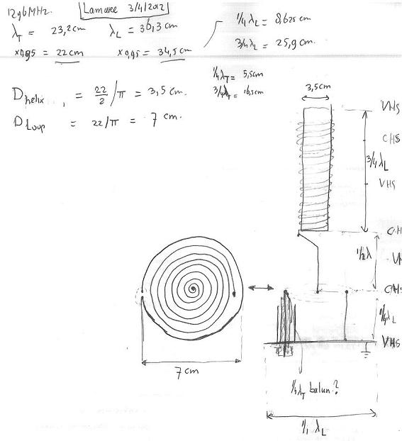
                  • First step towards a 1296 MHz Tesla transmitter..

                    I have thought the idea of using a loop feed as the primary in a scaled down Tesla transmitter a bit further trough and made a sketch in the train to work this morning:


                    Full res: http://www.tuks.nl/img/TeslaTM_1296_MHz.jpg


                    The "CHS" and "VHS" on the right of the sketch refers to Current Hot Spot and Voltage Hot Spot.

                    At the (top) open end of an oscillating coil obviously no current flows, so there you have a VHS. For a 3/4 lambda resonating coil, you thus have a CHS at the bottom end.

                    Since no current should flow trough the reflector ground plate, you should also have a VHS there.

                    Since both ends of the pancake coil are connected, we should have a CHS at the plane where our pancake coil is.

                    In other to match these hotspots, given our longitudinal wave propagates along the length direction of the coil, we should have a spacing of 1/4 lambda longitudinal between the ground plane and the pancake coil, and 1/2 lambda longitudinal between the pancake coil and the "extra" Tesla coil.


                    The primary of the pancake transformer is condisered to be a "loop feed", as is being used by radio amateurs at a/o the 23cm band. See:
                    HAM Radio of SM6FHZ 432 MHz Feed comparison
                    New Page 2
                    Loop feed for 144 MHz
                    80-20m Magnetic Loop Antenna by Frank N4SPP


                    This pdf has some very nice construction details for a loop feed:
                    http://www.om6aa.eu/Loop_Feed_DUBUS_Version.pdf


                    There are some questions that have to be worked out. First of all, it may be better to use a balun section around the feedline, which could be constructed similar to what I did with my previous antenna.

                    And we now have two ground connections. One from the feedline, and one from the outer terminal of the pancake coil. I have drawn them to be placed at oppozing ends of the construction, but that may give us some unwanted loop effects.

                    I have someone that made some simulations of my previous designs. Hopefully he is willing to help with this one too, so we can sort these things out before actually making an attempt to build one.

                    Update: It seems to me now that we have an LMD or TM wave propagating between the lower terminal of the extra coil and the ground plane, which propagates at the speed of light.

                    The purpose of the extra coil is to convert this TM wave into an LD wave, propagating at pi/2 times c. So, what this system does is to transform electromagnetic energy into pure dielectric energy.

                    This means for the design of the system that we have to calculate with a propagation speed of c for all components except for the extra coil.
                    Last edited by lamare; 04-03-2012, 06:02 PM. Reason: typo

                    Comment


                    • The other day I have been reading about the one terminal capacitor of a certain Joseph hiddink something that, as far as I know, noone has replicated.

                      Joseph Hiddink: One-Terminal Capacitor -- Articles & USP#4095162

                      Now at first sight you might ask what this has to do with your work. Well the idea is to actually, almost instantly, create a one terminal capacitor by "destroying" one terminal of a "capacitor". Or in other words have a charged monopole. This is done without any apparent current flow so there's no magnetic field associated. This monopole can thus radiate its static field outwards, do this in rapid succession and you can have your longitudinal electrical field.

                      Comment


                      • Lowrance Weave Coils

                        Last week, I was at a free energy gathering in France, where someone showed me the coils he used for healing purposes, whereby he used a very peculiar way of winding. He referred to it as cadeceus coils, but that was not what it actually was.

                        Today, I went googling for more information and found virtually nothing. But, I did find this:

                        ZPE_Coils
                        Weave Coil - Designed by David Lowrance based on the description of Wilbert Smiths writings, a coil with each single loop reversed from the one next to it. Loops are placed on the coil form then twisted around one another at each of 180 degree points along the sides of the coil moving upwards. Normally a one layer coil is plenty for a bismuth core to become notably strong using a function generator. This is the coil detailed in the RainMaker vortex generator.

                        From there, I found finally found some pictures:

                        Experiments
                        Specs

                        This is the way these "Lowrance Weave Coils" are wound:

                        And this is what it looks like:


                        This appears to be a very interesting idea to wind the top coil with, because this way of winding should always cancel out the magnetic field to a large degree, so you don't need to worry about how to get rid of the magnetic component in your top (or "extra") coil...

                        Comment


                        • Lamare,
                          I've been going over the high energy plasma notes and papers and some unpublished high altitude electrostatic research. What I'm coming away with is that the wave we are after the ES or pure electrostatic wave will maintain that wave type until it 'runs' into a boundary condition where it will convert to an EM wave and the resultant release of energy in photons, x-rays etc..

                          How to generate such a contained wave is the tricky part, the polarized beam of an EM wave can be guided due to it's conjugate pairing, however the ES wave is in parallel. in a vacuum the energy needed is less than in an atmosphere for plasma's due to the increased efficiency. A pure ES wave would have substantial difficulty in the atmosphere before the vacuum of space, snells N factor law comes to mind again here as it's also adapted to electron potential in QED.

                          Vacuum tubes are the perfect environment for an ES wave, the glass though is the boundary and subsequent EM conversion point. However the wave can be maintained theoretically within the tube. the tube apparatus then becomes the antennae and you'd need a receptive tube to detect the ES wave modulation.

                          EM to ES wave modulation is new-old research.

                          From how I see it, the ES longitudinal wave is not bound in our dimensional time frame, it's effect is only known when converted to an EM wave, thus a ES wave is hyper-dimensional, like the proposed gravity waves, maybe the same thing too. reflecting an ES wave is one area to look into. I'll dig some more and let you know if I find anything.

                          Comment


                          • I just realized that when people want to experiment with this antenna design, it could easily be scaled down for the 2.4 GHz band, so you can use a wifi device, such as a linksys Linux router, for a proof of concept for longitudinal communication.
                            This is relevant to my interests. I'd love to get this set up, though I'm not familiar with all the math. Just set it up to take the antennae signal from an 802.11 router and convert it. Doesn't matter if it's air or through the earth--house ground would work--if you can do it, and people can connect to it, it'd be cool.

                            It does make me wonder how resilient it would be though, how hard would it be to intercept, jam, or "radiolocate" a signal?

                            P.S. it's been a month, how's this project been going?

                            Comment


                            • Originally posted by T-rex View Post
                              From Radio Engineers Handbook:


                              Uploaded this chapter from the book to my server:

                              Directory contents of /img/Terman%20-%20Radio%20Engineers%20Handbook%20-%20Waveguides/

                              And the full book in pdf as well: http://www.tuks.nl/pdf/Reference_Mat...20-%201943.pdf

                              Originally posted by jpolakow View Post
                              Note to Lamare from Eric Dol lard-

                              [...]

                              Steinmetz sphere equations in the "Transient Phenomena" book may be of use. The 1920 edition has the right equations. I think your sphere should be driven by a self resonant coil, cut short to resonate with sphere capacity. Sphere capacity equal to coil self capacity is maximum sphere capacity allowed. Use my formula in "Theory of Wireless Power". No guesswork here, just basic high school math. Forget the physics of gobble-gook. For "Can" antennas if you want what is known as a Transverse Magnetic, TM waveguide mode. Here the dielectric is longitudinal along direction of propagation. See "Radio Engineer Handbook", Terman, and "Reference Data for Radio Engineers" I.T.T. published. Here your waveguide modes are presented. One in particular is very interesting as its lossed decrease with frequency but it is very hard to excite this mode. Check this out as it is directly regulated to your efforts in "moonbounce". Show modes on forum for others to see!

                              Also a "Tao" has his own great representation of the "Four Quadrant" "Eight Pole" representation on forum.

                              73 DE N6KPH SK
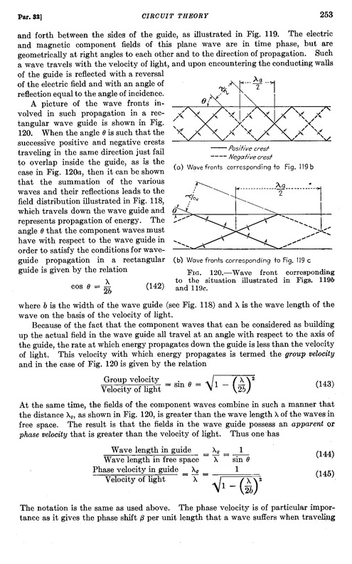
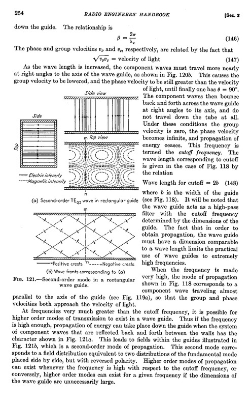
                              Today, I did some calculations with the formulas from Terman's book, but let's first go to page 253/254:


                              It says here:

                              ....the fields of the component waves (the dielectric and the magnetic??) combine in such a manner that the distance lambda_g, as shown in Fig. 120, is greater than the wavelength lambda of the waves in free space. The result is that the fields in the wave guide possess an apparent or phase velocity that is greater than the speed of light.
                              Aha!

                              Now what if we want this phase velocity, the "apparent velocity in the guide" to be pi/2 times c, the (postulated) propagation speed of longitudinal dielectric waves?


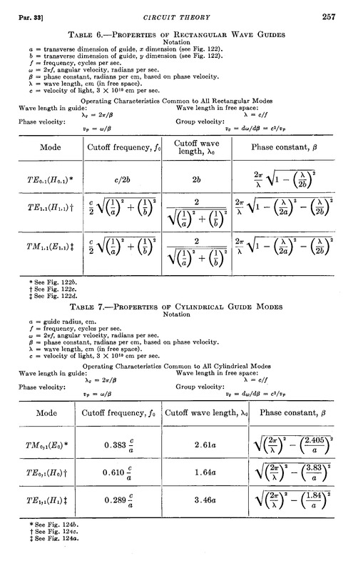
                              In table 7, some properties of different propagation modes are given for circular waveguides, the only type of waveguides that support the TM_0,1 mode.

                              It says a/o: lambda_g = 2 pi / beta. And we want this wavelength to be equal to pi/2 times the wavelength in free space, or:

                              2 pi / beta = pi/2 * lambda.

                              This requires beta to be equal to 4 / lambda.

                              From table 7, we can see the formula for beta as a function of lambda and a, a/o for the TM_0,1 mode, which we take equal to 4 / lambda.

                              When we work that out, we get:

                              a = SQRT ( 2,405^2 / ( 4 pi^2 - 16 ) ) * lambda,

                              which computes to:

                              a = 0.4963416 * lambda.

                              (note that a denotes the *radius* of the waveguide, not the diameter)

                              In other words: if we take a circular waveguide with a diameter equal to the free space wavelength lambda, we get an "apparent" group velocity of pi/2 times c within our waveguide, all according to accepted theory, literally "by the book"

                              For this diameter, only two propagation modes are possible, namely the TM_0,1 and the TE_1,1 mode.

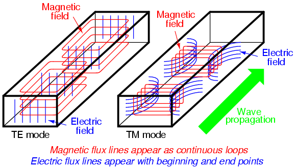
                              In this image, you can see the fundamental difference between TE and TM modes, although this is definitely not the TM_0,1 mode, since that is not supported by rectangular waveguides:

                              Waveguides : Transmission Lines


                              If you look at the magnetic lines and remember the right hand rule, it is clear that the "current", or aether movement, is in the other direction:


                              With a TE mode, we get "up and down" "current" or "movement of the aether", while with the TM mode, we get movements along the length direction of the wave guide.

                              So, it seems like all we need to do is figure out how this TM_0,1 mode can best be excited. Yes, Terman gives some hints, but so far I have not been able to find any detailed information.

                              In other news, the dish in Dwingeloo has been restored and looks as good as new:


                              More here, including some vids:
                              Korte impressie van het terugplaatsen van de spiegel

                              Comment


                              • If longitudinal waves aren't shielded from faraday cages, then you could transmit a signal at a power or frequency of which a transverse wave can not penetrate the ionosphere, which would further increase the validity of the experiment.

                                Comment

                                Working...
                                X